Sign In
Upload
Manuals
Brands
MV Agusta Manuals
Motorcycle
Rivale 800
MV Agusta Rivale 800 Manuals
Manuals and User Guides for MV Agusta Rivale 800. We have
2
MV Agusta Rivale 800 manuals available for free PDF download: Workshop Manual, User Manual
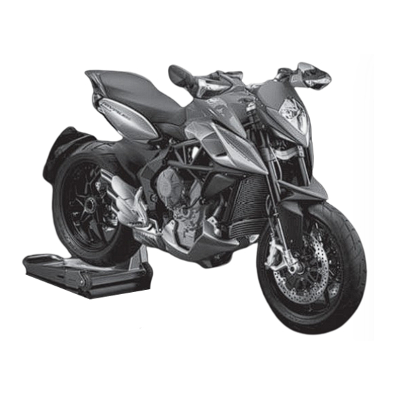
MV Agusta Rivale 800 Workshop Manual (457 pages)
Brand:
MV Agusta
| Category:
Motorcycle
| Size: 46.17 MB
Table of Contents
General Index
5
General Description
7
Table of Contents
8
Summary
8
How to Consult this Manual
9
Order of the Subjects
9
Display of the Operations
9
Glossary and Symbols
10
Right Hand and Left Hand Standard
11
Carbon Monoxide
12
Petrol
12
Engine Oil
12
Safety
12
Battery
13
Thread-Locking Fluid
13
Nitrogen - Rear Shock Absorber
13
Brake Fluid
13
Index
14
Motorcycle Identification
15
Operative Technical Specifications
15
Maintenance
17
Technical Data
19
Technical Information
19
Periodical Maintenance Schedule
22
Programmed Maintenance Schedule
22
Engine Oil and Oil Filter
24
Maintenance and Tuning Operations
24
Table of Lubricants and Fluids
24
Engine Coolant
27
Oil Pipes
27
Engine Coolant Substitution
29
Electric Cooling Fan
31
Valve Mechanism Adjustment
31
Spark Plugs
36
Timing Chain, Mobile Timing Chain Guide and Timing Chain Tensioner
36
Electrode Condition
37
Heat Grade
37
Spark Plug Gap
37
Fuel Filters
38
Removing the Fuel Pump Unit
38
Changing the Thermistor (Reserve Probe) Complete with Cabling
39
Check and Replace the Gasket
39
Replacement the Fuel Filter
40
Fuel Pump Assembly
41
Check, Disassembly and Reassembly Fuel Pipe Fittings
42
Installing the Fuel Pump Unit
42
Replacing Fuel Pipe in Tank
43
Replacing Fuel Pipe from Throttle Body
44
Checking Engine During Idle
45
Air Filter
46
Brakes
47
Checking the Level of the Rear Brake Fluid
49
Substitution and Bleeding of the Brake Fluid
51
Adjusting the Clutch Play
52
Brake / Clutch / Gearchange Commands Check
52
Front Brake Lever Adjustment
52
Adjusting the Gear Lever
54
Accelerator Control
55
Brake Pads
55
Ignition/Steering Block Switch
56
Locks
56
“OFF” Position
56
“ON” Position
56
Fuel Cap Lock
57
“LOCK” Position
57
Personal Compartment Lock
58
Steering
59
Transmission Chain
59
Chain Lubrication
61
Front Wheel Bearings
62
Tyres
62
Rear Wheel Hub
63
Swingarm Bearings
63
Rear Shock Absorber
64
Side Stand
64
Battery
67
Electrical System
67
Front Fork
67
Mounting Battery Terminals
68
Instruments and Warning Lights
70
Multifunction Display
71
Selecting and Setting the Display Functions
72
Selecting the Display Functions
72
“RUN” Mode
73
“SPEED LIMITER” Mode
73
“TC” Mode
73
“ABS” Mode
74
“CHRONO” Mode
74
“QUICK SHIFT” Mode
74
Trip Reset
75
“CLOCK” Mode
75
Chronometer
79
Lap Time Recording
79
Data Display
80
How to Delete Data
82
Selecting the ABS Functions
85
Clock Settings
87
How to Select the Mapping of the Control Unit
88
Setting of “Custom” Mapping
88
Warning / Malfunction Alerts
96
Dealer Menu
97
“SERVICE” Mode
98
“UNIT CHANGE” Mode
98
Changing the Unit of Measurement
100
Lights
101
Replacing the Headlight Bulb
101
Fuses
104
Front Headlamp
107
Headlight Adjustment
107
Superstructures
109
Fairings
111
Front Headlight Cover Disassembly
112
Removing Front Mudguard
112
Headlight Support Disassembly
114
Dashboard Disassembly
115
Removing Handlebar
116
Fuel Tank
120
Disassembly of Number Carrier Side Panels and Seat Rail Side Panels
121
Removing Fuel Tank
124
Removal of Fuel Tank Cap
126
Radiator Side Panels
128
Intake Air System - Airbox
131
Removing Airbox
132
Airbox Removal
133
Rear Tail
136
Lower Bulkhead and Tail Light
137
Tail Tidy Disassembly
138
Disassembly of the Frame Lower Bulkhead
139
Foot Peg Support Disassembly
139
Disassembly of the Glove Compartment Bulkhead
140
Removing Number Plate Support
140
Disassembly of the Complete Mudguard Number Plate Carrier Unit
144
Disassembly of Exhaust Guards
150
Tail Light Disassembly
150
Air Intake Injection System
153
Injection System Technical Characteristics
155
Injection Time (Injection Volume)
155
Injection Arrest Control
156
Injection Time Compensation (Volume)
156
Fuel Feed System
157
Fuel Injector
158
Fuel Pressure Regulator
158
Fuel Pump Control System
159
Atmospheric Air Temperature Sensor
160
Ecu (Electronic Control Unit)
160
Intake Air Pressure Sensor
160
Intake Air Temperature Sensor
161
Throttle Body Position Sensors
162
Fuel Pump Check
163
Injector Check
163
Ignition Coils
165
Diagnostics System
166
Ignition and Injection System Diagnostics
166
Eldor Power Unit Fault Codes (with TEXA Diagnostic Software)
167
Air Intake System Technical Characteristics
176
Positions of Engine-Control System Parts
177
Injection System Electrical Diagram
178
Engine Control Unit Pinout, MV Agusta Rivale 800
179
Electrical System
181
Connectors
183
Couplings
183
Semiconductor Parts
184
Electrical Diagram
185
Fuses List
186
Parts List
186
Wiring Colour Code
186
Charging the Battery
190
Removal of the Battery
191
Charging System
192
Warning Function
192
Battery Current Loss Check
194
Battery Current Loss: Less than 1Ma
194
Battery Efficiency Check
194
Charge Feed Check
194
Feed Charge
195
Starter System
195
Checking the Generator
199
Starter Motor Removal
200
Starter Motor Assembly
201
Starter Motor Check
201
Starter Relay Check
201
Tilt Sensor
202
Gearchange Position Switch
203
Side Stand Switch
203
Fuses Rivale 800
204
Fuses Rivale 800 ABS
204
Main Relay
206
E.A.S. (Electronically-Assisted Gear Shift)
207
Engine Pick-Up
207
Run off Safety Switch
208
Timing Wheel Gap
208
Instrumentation
209
Fuel Level Warning Light Check Switch
210
Oil Pressure Sensor
210
Water Sensor
211
Keu Switch
212
R.P.M. Sensor
212
Turn Indicators
212
Dipping Beam
213
Rivale 800
213
Rivale 800 ABS
213
Speed Sensor
213
High Beam Headlight
214
Licence Plate Light
215
Rear Tail Lights and Brake Lights
216
Front Turn Indicators Indicator and Side Light
217
Rear Turn Indicator Lights
218
Cooling Fan System
219
ECU Disassembly
220
Engine Control Unit Replacement/Programming
220
Horn
220
Engine Control Unit Pinout
221
Replacement of the ASB Unit
221
ABS Unit Activation
224
Switches
226
Positioning of Electrical System Wire Clamps Rivale 800
227
Positioning of Electrical System Wire Clamps Rivale 800 ABS
240
Suspension and Wheels
245
Front Wheel
247
Front Wheel Removal
248
Front Wheel Bearing Check
250
Front Wheel Bearing Replacement
250
Reassembly – Front Wheel Bearings
251
Wheel Assembly
253
Wheel Spindle Check
253
Front Fork
254
Fork Tube Exploding
255
Front Fork Overhaul
255
Stem Removal
255
Assembly Oil Seal and Anti-Dust Seal
260
Fork Assembly Check
260
Adjusting the Front Suspension
267
Rebound Damper
267
Spring Preload
267
Compression Damper
268
Steering Assembly
269
Steering Assembly Overhaul
270
Steering Head Removal
271
Steering Base Removal
272
Assembly Steering Base
273
Steering Head Assembly
274
Steering Pin Tightening
274
Rear Suspension and Swingarm
275
Rear Shock Absorber Disassembly
276
Rear Shock Absorber Test
277
Adjusting the Rear Suspension
278
Rear Shock Absorber Assembly
279
Pinion Cover Removal
280
Rear Wheel Removal
280
Swingarm Removal and Overhaul
280
Footrest Removal
281
Lower Chain Guard Removal
282
Silencer Disassembly
282
Top Chain Guard Removal
282
Chain Removal
284
Reassembling Chain
285
Riveting of Pin
286
Removing the Rear Brake Caliper
287
Speed Sensor Cable Disassembly
287
Swingarm Pin Removal
288
Upper Chain Guide Removal
289
Bearings Overhaul
290
Lower Chain Guide Removal
290
Rear Wheel Hub
293
Brake Caliper Support Flange Removal
297
Disassembly of the Wheel Pin
297
Caliper Holder Pin
298
Wheel Hub Disassembly
298
Wheel Spindle Unit Check
299
Crown Wheel Assembly Check
300
Flexible Coupling Check
301
Reassembly Wheel Hub
302
Reassembly Rear Wheel Pin
303
Rear Wheel Assembly
305
Pinion Disassembly
306
Motorcycle Set-Up Adjustment
310
Front Wheel Balancing
312
Rear Wheel Balancing
312
Wheel Balance Check
312
Frame
315
Battery Cables
317
Preliminary Operations
317
Foot Peg Removal
319
Exhaust Silencer Disassembly
320
Exhaust Manifolds Removal
321
Frame Removal Preliminary Operations
323
Control Unit Removal
324
Battery Box Removal
326
Glove Compartment Removal
327
Removal of Ignition Switch
328
Expansion Tank Removal
330
Disconnecting the Horn
333
Throttle Body Removal
333
Removing the Seat Lock
337
Removing the Main Cabling
338
Removing Clutch Control Transmission
341
Frame Removal from the Engine
342
Frame Checks and Inspection
344
Frame Measurements Control Diagram
346
Steering Bearings Housing Check
347
Frame Assembly Pn the Vehicle
348
Rear Frame Disassembly
352
Removal of the Starter Contactor and Fuse Box
353
Rear Frame Unit Assembly
355
Engine Removal
356
Re-Assembly of the Vehicle
360
Brakes
361
Front Brake System
363
Front Brake Pads Substitution
364
Removing Front Mudguard
364
Substitution and Bleeding of the Front Brake Fluid
366
Front Brake Calipers Substitution
371
Front Brake Pump Removal
372
Front Brake Lever Removal
377
Front Brake Disc Removal
378
Front Disc Assembly
379
Rear Brake System
380
Rear Brake Pads Substitution
381
Substitution and Bleeding of the Rear Brake Fluid
383
Rear Brake Caliper Substitution
385
Rear Brake Pump Removal
387
Rear Brake Disc
389
Rear Brake Disc Removal
390
Cooling System
393
Cooling System
394
Complete Cooling System Assembly
395
Checking Expansion Tank Cap
396
Cooling System Leakage Check
396
Draining the Coolant
397
Water Radiator Cap Check
397
Removing Expansion Tank
399
Water Radiator Disassembly
401
Disassembly of the Electric Fan
407
Disassembly of the Water Radiator Parts
407
Disassembly of the Radiator Clamping Elements
408
Disassembly of the Liquid Temperature Sensor
410
Check
411
Assembly of the Liquid Temperature Sensor
412
Cooling Fan Motor Check
412
Water Radiator Group Assembly
412
Thermostat Removal
414
Standard
415
Thermostat Assembly
416
Water Radiator Vehicle Unit Assembly
417
Oil Radiator Disassembly
418
Oil Radiator Component Disassembly
421
Removal of Spacers and Silent Blocks
421
Removing the Connecting Pipes
421
Oil Radiator Assembly
422
Filling the Cooling System
427
Motor Oil System Filling
429
System Functioning Check
430
Motor Oil System
430
Special Tools
431
Maintenance Tools
432
Special Tools
433
Tightening Torques
439
Diagnostic
443
Electrical Components
444
Analytical Index
451
Advertisement
MV Agusta Rivale 800 User Manual (93 pages)
Brand:
MV Agusta
| Category:
Motorcycle
| Size: 2.41 MB
Table of Contents
Table of Contents
4
Subjects Covered
4
1 General Information
6
Purpose of the Manual
6
Multifunction Display 27
6
Symbols
7
Contents of the Digital Support
8
Identification Data
9
2 Safety Information
12
Allowed Use of the Vehicle
12
Maintenance
12
Accessories and Modifications
13
Vehicle Load
13
3 Controls and Instruments
15
Location of Controls and Instruments
15
Sidestand
16
Handlebar Controls, Left Side
17
Handlebar Controls, Right Side
19
Ignition Switch and Steering Lock
22
Gear Lever
25
Instruments and Warning Lights
26
Warning Lights
27
Table of Lubricants and Fluids
29
4 Operation
30
Using the Motorcycle
30
Running-In
31
Starting the Engine
33
Selecting and Setting the Display Functions
36
Selecting the Display Functions
37
Trip Reset
42
SPEED LIMITER" Mode
44
TC" Mode
46
Chronometer
47
ABS Mode
56
QUICK SHIFT" Mode
58
Clock Settings
59
How to Select the Mapping of the Control Unit
61
Warning/Malfunction Alerts
73
Refuelling
76
Glove Compartment
78
Parking the Motorcycle
79
Adjustments
81
List of Adjustments
81
Table of Adjustments
83
Adjusting the Front Brake Lever
84
Adjusting the Rearview Mirrors
84
Adjusting the Front Suspension
85
Spring Preload (Front Suspension)
85
Compression Damper (Front Suspension)
86
Rebound Damper (Front Suspension)
86
Adjusting the Rear Suspension
87
Rebound Damper (Rear Suspension)
88
Compression Damper (Rear Suspension)
89
Headlight Adjustment
90
Advertisement
Related Products
MV Agusta 8A00B3246
MV Agusta BRUTALE 800 RR
MV Agusta TURISMO VELOCE 800 LUSSO
MV Agusta Rivale 800cc
MV Agusta BRUTALE 800 2017
MV Agusta BRUTALE 800 RC 2017
MV Agusta 2005 F4 BRUTALE 910 S
MV Agusta 2008 F4 312RR 1078
MV Agusta 2011 F3 675
MV Agusta 2012 Brutale 675
MV Agusta Categories
Motorcycle
Bicycle
Engine
Motocycles
More MV Agusta Manuals
Login
Sign In
OR
Sign in with Facebook
Sign in with Google
Upload manual
Upload from disk
Upload from URL