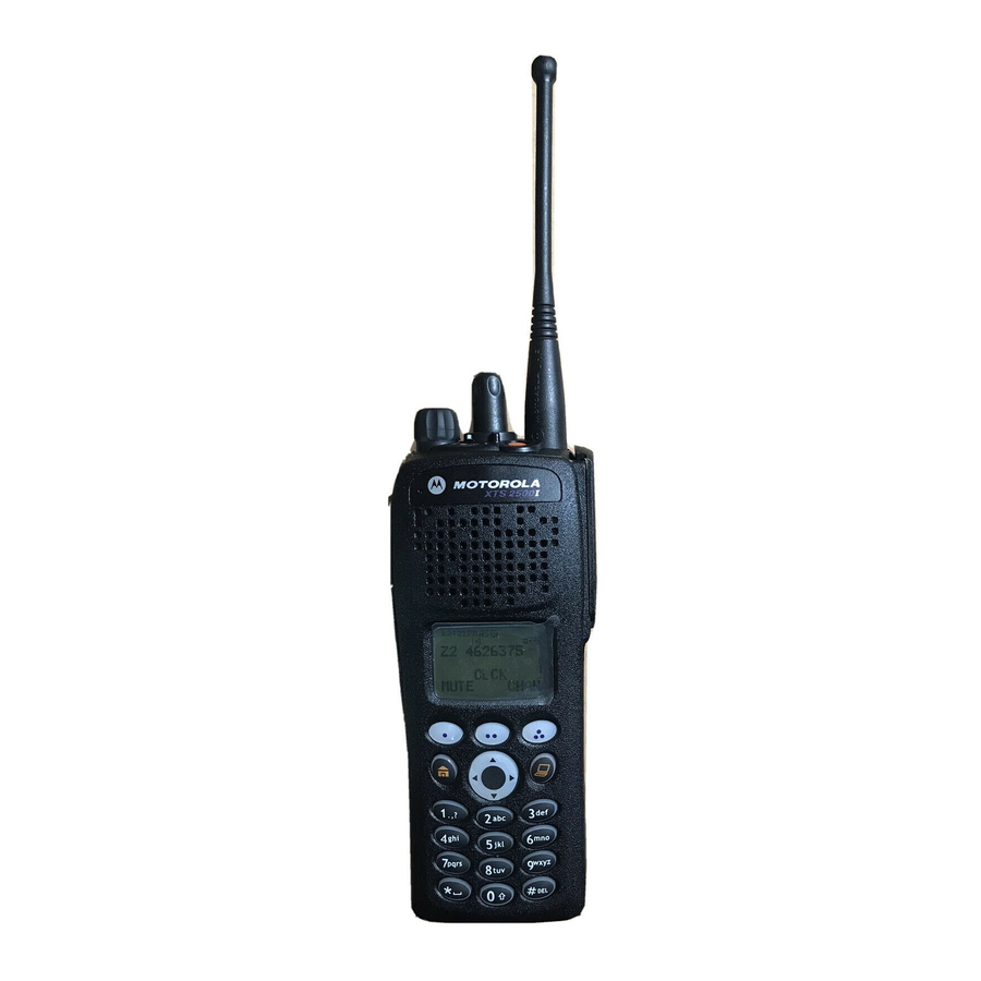
Motorola ASTRO XTS 2500 Manuals
Manuals and User Guides for Motorola ASTRO XTS 2500. We have 14 Motorola ASTRO XTS 2500 manuals available for free PDF download: Service Manual, User Manual, Basic Service Manual, Editing Manual
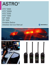
Motorola ASTRO XTS 2500 Service Manual (817 pages)
Brand: Motorola
|
Category: Portable Radio
|
Size: 44.21 MB
Table of Contents
Advertisement
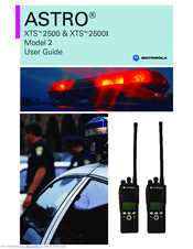
Motorola ASTRO XTS 2500 User Manual (138 pages)
Model II
Brand: Motorola
|
Category: Portable Radio
|
Size: 10.78 MB
Table of Contents
Motorola ASTRO XTS 2500 Basic Service Manual (88 pages)
700 - 800 MHz Digital Portable Radios
Brand: Motorola
|
Category: Portable Radio
|
Size: 6.46 MB
Table of Contents
Advertisement
Motorola ASTRO XTS 2500 User Manual (106 pages)
Model III
Brand: Motorola
|
Category: Portable Radio
|
Size: 3 MB
Table of Contents
Motorola ASTRO XTS 2500 User Manual (82 pages)
Brand: Motorola
|
Category: Two-Way Radio
|
Size: 1.66 MB
Table of Contents

Motorola ASTRO XTS 2500 User Manual (82 pages)
Brand: Motorola
|
Category: Portable Radio
|
Size: 1.59 MB
Table of Contents

Motorola ASTRO XTS 2500 User Manual (82 pages)
Digital Portable Radio
Brand: Motorola
|
Category: Portable Radio
|
Size: 9.59 MB
Table of Contents
Motorola ASTRO XTS 2500 User Manual (78 pages)
Digital Portable Radio
Brand: Motorola
|
Category: Portable Radio
|
Size: 3.33 MB
Table of Contents

Motorola ASTRO XTS 2500 User Manual (156 pages)
Motorola ASTRO XTS 2500; ASTRO XTS 2500I Digital Portable radio
Brand: Motorola
|
Category: Portable Radio
|
Size: 2.18 MB

Motorola ASTRO XTS 2500 User Manual (138 pages)
Brand: Motorola
|
Category: Two-Way Radio
|
Size: 1.99 MB

Motorola ASTRO XTS 2500 Basic Service Manual (98 pages)
Brand: Motorola
|
Category: Portable Radio
|
Size: 14.03 MB

Motorola ASTRO XTS 2500 User Manual (70 pages)
Digital Portable Radio
Brand: Motorola
|
Category: Portable Radio
|
Size: 2.96 MB

Motorola ASTRO XTS 2500 User Manual (2 pages)
Brand: Motorola
|
Category: Portable Radio
|
Size: 0.49 MB
Table of Contents

Motorola ASTRO XTS 2500 Editing Manual (3 pages)
Brand: Motorola
|
Category: Portable Radio
|
Size: 0.39 MB