Sign In
Upload
Manuals
Brands
Midland Manuals
Portable Radio
STP-404B
Midland STP-404B Manuals
Manuals and User Guides for Midland STP-404B. We have
1
Midland STP-404B manual available for free PDF download: Service Manual
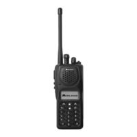
Midland STP-404B Service Manual (77 pages)
VHF and UHF
Brand:
Midland
| Category:
Portable Radio
| Size: 5.16 MB
Table of Contents
Table of Contents
6
Definitions, Abbreviations and Acronyms
8
Definitions
8
Abbreviations and Acronyms
8
Introduction
11
General Features
11
Technical Specifications
12
Table 2-1: Syn-Tech III P25 Portable Radio General Specifications
12
Table 2-2: Batteries for Syn-Tech III P25 Portable Radios
12
Table 2-3: Syn-Tech III P25 Portable Radio Environmental Specifications
12
Table 2-4: Syn-Tech III P25 Portable Radio Receiver Specifications
13
Table 2-5: Syn-Tech III P25 Portable Radio Transmitter Specifications
14
Description of the Radio
15
Connection Diagram
15
Figure 3-1: Midland Syn-Tech III P25 Portable Radio Connection Diagram
15
Operating Principles
16
RF and Control PCB
16
Display and Keypad PCB
18
Dsp Pcb
18
Table 3-1: KN1, RF and Control PCB to DSP PCB Signals
20
Table 3-2: KN2, RF and Control PCB to Display and Keypad PCB Signals
21
Adjustment
22
Definitions and Abbreviations
22
Adjustment Conditions
22
Adjustment Setup
22
Table 4-1: Spurious Signal Frequencies
22
Figure 4-1: Adjustment Setup
23
Adjustment Procedures
24
RF Output Power Adjustment
24
Analog Frequency Adjustment 25 Khz
24
Digital Frequency Adjustment
24
Modulation Flatness Adjustment
24
Modulation Limiting Adjustment
25
FM Deviation Adjustment
25
C4FM Deviation Adjustment
25
Squelch Adjustment
25
RSSI Adjustment
26
C4FM Receive Level Adjustment
26
Troubleshooting
27
Table 5-1: Syn-Tech III P25 Portable Radio Error Messages
27
Table 5-2: Syn-Tech III P25 Portable Radio Alert Messages
28
Table 5-3: Syn-Tech III P25 Portable Radio 'Problem-Solution' Table
29
Illustrated Part Lists
31
Syn-Tech III P25 Portable Main Assemblies
32
Figure 6-1: Main Assemblies Location Diagram
32
Table 6-1: Main Assemblies Parts List
33
Syn-Tech III P25 Portable Radio Pcb Assemblies
34
Figure 6-2: PCB Assemblies Location Diagram
34
Table 6-2: PCB Assemblies Parts List
35
Syn-Tech III P25 Portable Radio Rear Panel Assembly
36
Figure 6-3: Rear Panel Assembly Location Diagram
36
Table 6-3: Rear Panel Assembly Parts List
37
Syn-Tech III P25 Portable Radio Front Panel Assembly
38
Figure 6-4: Front Panel Assembly Location Diagram
38
Table 6-4: Front Panel Assembly Parts List
39
Syn-Tech III P25 Portable Radio Display and Keypad Pcb Assembly
40
Table 6-5: Display and Keypad PCB Parts List
42
Syn-Tech III P25 Portable Radio Dsp Pcb Assembly
44
Table 6-6: DSP PCB Parts List
46
Syn-Tech III P25 Portable Radio Vhf Rf and Control Pcb Assembly
47
Table 6-7: VHF RF and Control PCB Assembly Parts List
49
Syn-Tech III P25 Portable Radio Uhf Rf and Control Pcb Assembly
54
Table 6-8: UHF RF and Control PCB Assembly Parts List
56
Disassembly and Assembly
61
Required Equipment
61
Usage
62
Disassembling the Radio
62
Disassembling the Pcb Assembly
65
Schematic Diagrams
68
UHF RF SCHEMATIC 450-512 Mhz
68
Radio Connector Pinout
69
Control Schematic
73
Dsp Schematic
74
Lcd and Keypad Schematic
75
Advertisement
Advertisement
Related Products
Midland STP-105B
Midland STP-404A
Midland SP-400 Series
Midland street guardian
Midland STREET GUARDIAN NIGHT
Midland STREET GUARDIAN GPS+
Midland Street Guardian +
Midland STR180
Midland Subzero sportek
Midland SPD-6
Midland Categories
Two-Way Radio
Transceiver
Radio
Action Cameras
Intercom System
More Midland Manuals
Login
Sign In
OR
Sign in with Facebook
Sign in with Google
Upload manual
Upload from disk
Upload from URL