Sign In
Upload
Manuals
Brands
JRC Manuals
Transceiver
JST-135
JRC JST-135 Manuals
Manuals and User Guides for JRC JST-135. We have
3
JRC JST-135 manuals available for free PDF download: Service Manual, Instruction Manual
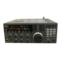
JRC JST-135 Service Manual (136 pages)
Brand:
JRC
| Category:
Transceiver
| Size: 4.67 MB
Table of Contents
Introduction
2
Contents
2
Parts Identification
3
Specifications
4
Block Diagram
5
Signal Flow
5
Synthesizer System
6
Circuit Description
7
Block and Units
7
Description of Units
8
RF Tune Unit
8
IF Fil Unit
8
Band Classification in RF Tuning Circuit
8
IF AMP Unit
9
BFO and Product Detection Frequencies
9
PA Unit
10
LPF Unit
10
Filter Selection Code, LPF Unit
10
REF/DDS Unit (CGK - 81A)
11
DDS Waveforms
11
PLL IC Configuration
12
Loop 1 Unit
13
Loop 1 PLL Configuration
13
CPU Unit
14
AF AMP Unit
14
Description of Optional Units
15
Tone SQ Unit CCL-212
15
BWC Unit CFL-243
15
Notc Follow Unit CDD-366
15
RS 232C Interface Unit CMH-741
16
ECSS Unit Configuration
16
Adjustment
17
Preparation
17
Presetting
17
Required Measuring Instruments
17
Standard Test Circuit
18
Notes
18
Sensitivity Measurement
18
Power Output Measurement (SSB)
18
Unit Adjustment
19
PA Unit CAH-301L-2
19
AF AMP Unit CBD-894L
20
CPU Unit CDC-493A
21
Display Unit CDE-576
22
Loop 1 Unit CGA-145
23
REF DDS Unit CGK-81A
24
IF AMP Unit CAE-227
25
IF Filter Unit CFH-38A
28
RF Tune Unit CFL-244
31
Overall Adjustment
33
Receiver
33
Transmitter
34
Level Diagram
35
Assembly Drawing
37
Circuit Diagram, Component Layout and Parts List
40
RF Tune Unit CFL-244 Circuit Diagram
41
RF Tune Unit CFL-244 Component Layout
42
Parts List
43
IF Filter Unit CFH-38A Circuit Diagram
50
IF Filter Unit CFH-38A Component Layout
51
IF AMP Unit CAE-227 Circuit Diagram
58
IF AMP Unit CAE-227 Component Layout
59
12V PA Unit CAH-301L.2 Circuit Diagram
68
12V PA Unit CAH-301L.2 Component Layout
69
LPF Unit CF1-122.2 Circuit Diagram
73
LPF Unit CF1-122.2 Component Layout
74
Loop 1 Unit CGA-145 Circuit Diagram
79
Loop 1 Unit CGA-145 Component Layout
80
REF DDS CGK-81A Circuit Diagram
84
REF DDS CGK-81A Component Layout
85
CPU Unit CDC-493A Circuit Diagram
91
CPU Unit CDC-493A Component Layout
92
Display Unit CDE-576 Circuit Diagram
96
Display Unit CDE-576 Component Layout
97
Display (VR) Unit CDE-576 Circuit Diagram
98
Display (VR) Unit CDE-576 Component Layout
99
AF AMP Unit CBD-894L Circuit Diagram
104
AF AMP Unit CBD-894L Component Layout
105
Tone SQ Unit CCL-212 Circuit Diagram
108
Tone SQ Unit CCL-212 Component Layout
109
BWC Unit CFL-243 Circuit Diagram
111
BWC Unit CFL-243 Component Layout
112
Notch Follow Unit CDD-366 Circuit Diagram
116
Notch Follow Unit CDD-366 Component Layout
117
ECSS Unit CMF-78 Circuit Diagram
119
ECSS Unit CMF-78 Component Layout
120
RS-232C Interface Unit CMH-741 Circuit Diagram
125
RS-232C Interface Unit CMH-741 Component Layout
126
Mother Board CFQ-2625A Circuit Diagram
128
Chassis JST-135 Circuit Diagram
128
Signal Nomenclature of Units
129
Mother Board CFQ-2625A Component Layout
130
Advertisement
JRC JST-135 Instruction Manual (62 pages)
HF
Brand:
JRC
| Category:
Transceiver
| Size: 6.28 MB
JRC JST-135 Instruction Manual (44 pages)
Brand:
JRC
| Category:
Transceiver
| Size: 4.37 MB
Advertisement
Advertisement
Related Products
JRC JST-125
JRC JST-245
JRC JST-145
JRC JST-100
JRC JHS-431
JRC JHP-500 Com
JRC JHP-520 Nav/Com
JRC JSS-596 -
JRC JSS-896 -
JRC JSS-2150 -
JRC Categories
Water Filtration Systems
Marine Radar
Marine Equipment
Radio Parts
Receiver
More JRC Manuals
Login
Sign In
OR
Sign in with Facebook
Sign in with Google
Upload manual
Upload from disk
Upload from URL