Sign In
Upload
Manuals
Brands
JRC Manuals
Marine Radio
JSS-596 -
JRC JSS-596 - Manuals
Manuals and User Guides for JRC JSS-596 -. We have
2
JRC JSS-596 - manuals available for free PDF download: Service Manual, Brochure
JRC JSS-596 - Service Manual (221 pages)
250W/500W/800W MF/HF Radio Equipment
Brand:
JRC
| Category:
Radio
| Size: 12.6 MB
Table of Contents
Table of Contents
3
1 Introduction
5
General
5
Installation Location
5
Grounding
5
Standard Components
6
Options
6
Feeder Kit for NAW-208S
7
Installation Materials
8
Antenna Materials
9
2 System Diagram
10
GMDSS Console System Configuration
10
GMDSS Console Interconnection Diagram
15
3 Installation
19
Selecting the Antenna Location
19
Comparison of Antenna Electrical Origin
20
Improper Counterpoise
20
Proper Counterpoise
20
Mf/Hf Radio Equipment Installation
21
AC and DC Connections
21
Power Cable Connection
21
GMDSS Console Installation
22
NCU-331E/F/G GMDSS Console
22
NCU-324E/F/G GMDSS Console
23
NCU-1960 GMDSS Console
24
Ncu-692 Pa Rack Installation
25
Antenna Tuner Installation
26
Indoor Installation
27
Outdoor Installation
28
Pre-Installation Precautions
28
Installation Precautions
28
Post-Installation Precautions
28
Antenna Tuner
29
Bolting the Antenna Tuner
30
Bolting the Mounting Bracket
30
RF Cable
31
Connecting the Antenna
31
Wrapping RF Cable
31
Junction Box INSTALLATION
32
Outline Drawing
32
Connection Diagram
33
NFC-296 Numbered BC24351 or Later / NFC-896
33
NFC-296 Numbered from BC22067 to 24090
33
Junction Box-GMDSS CONSOLE/PA RACK Cable Connection
35
Printer INSTALLATION
36
Ensuring Maintenance Space and Positioning
36
Printer Maintenance Space
36
Notes on Using the Printer
37
Names and Functions
38
Operating Panel
39
Page Feed Switch
39
NLQ Lamp
39
Online Lamp
39
Opening / Closing the Printer Cover
40
Replacing the Roll Paper
41
Insert the Roll Bar through the Center of the Paper Roll
41
Replacing the Ribbon Cassette Cartridge
46
Adjusting the Printing Pressure (to Printing Paper Thickness)
48
Connection of NCH-321A Distress Message Controller
49
Initial -Setting
50
Unit Setting Procedure
50
NAH-692/695/698 Power Amplifier
51
Charge Function Setting
51
Battery and Charge Voltage Setting
51
Battery Operation Setting
52
PA VC (78V) Setting
52
BIAS-Level Adjustment
53
User Definitions (Level 2 MENU)
54
NKG-800 Printer
55
Character Setting
55
Printer Selector
57
Printer Selector SW-ATB21K(2:1)
57
MODE Switch
57
TIME out Switch
57
NCT-196N DSC/NBDP Modem
58
Self ID, Navigation and Radiotelephone Setting
58
Dip Switch Setting
58
NMEA0183 Format
59
Transmission Format
59
Data Format
59
JRC Format
59
Frequency Scanning / Frequency Calling / Date & Time Settings
60
Displaying the “SETUP” Display
60
Scanning Frequency Settings
61
Calling Frequency Settings
62
Date & Time Settings
63
DSC Space and Mark Measurement
64
A Reference Method of Distress Transmission History
65
Operation Check
66
NDZ-127J Data Terminal
68
NBDP Setting
68
JSB-196GM Radiotelephone
70
Operation Check
70
User Channel Registration
71
Input the RX/TX Frequency
71
Semi-Duplex Frequency Registration
71
Group Name Registration for User Channel
72
Test Tone Setting
73
Max Power Setting
74
DC TX Power Table
74
AC TX Power Table
74
TX Power Adjustment
75
Band Power Setting
75
User Channel Power Setting
77
User Definitions (Level 2 MENU)
78
Set up of the MENU Items
80
5 Troubleshooting
81
Jsb-196Gm
81
No Receiving Sound
81
Nct-196N
82
No Display on the LCD
82
No Response from Keys
82
Messages Not Received
83
Messages Not Transmitted
83
Cannot Select "DSC Watching"
84
Printer Does Not Print
84
Nah-692/695/698
85
Nkg-800
85
Message of JSB-196GM Operation Check and Management
86
NAH Check 2
88
NFC Check 1
88
6 Block Diagram
89
JSS-296/596/896 MF/HF Radio Equipment Block Diagram
89
JSB-196GM MF/HF Radio Equipment Block Diagram
90
Descriptions
91
Signals From/To Other Units
91
Nah-692/695/698
91
NCT-196N DSC/NBDP Modem Block Diagram
92
Description
93
Signals From/To the Other Units
94
NAH-692/695/698 Power Amplifier Block Diagram
95
Description
96
Signals From/To Other Units
96
NFC-296/896 Antenna Tuning Unit Block Diagram
97
Description
98
Signals From/To Other Units
98
7 Parts List
99
8 Check List
100
Circuit Diagram
105
Objective Equipment
152
Attached Document
152
CFG-296 Matching Unit Replacement Procedures
153
CFG-296 Replacement Procedures a
154
CFG-296 Replacement Procedures B
158
CFG-296 Replacement Procedures C
161
NFC-296 Antenna Tuner / CFG-296 Matching Unit Circuit Diagram
164
NCU-692 DC Breaker Addition Procedures
180
JSB-196/JSB-196GM Upgrading Procedures (JD-1301-04)
191
In the Case of NCT-196N
192
In the Case of NDZ-127J
192
JSB-196/GM Software Upgrading
192
Checking of User Channel Data
192
Upgrading of TRX Software
193
Upgrading of DSP Software
193
NCT-196N Upgrading
193
NDZ-127J Upgrading
193
Checking of JSB-196/JSB-196GM, JSS-296/596/896 Software Versions
194
Checking JSB-196/JSB-196GM Channel Data
195
Setting of JSB-196/JSB-196GM User Channel
197
Simplex Frequency Registration
197
Channel Power Adjustment
199
JSB-196/JSB-196GM TRX Software Upgrading Procedures
200
Jsb-196/Jsb-196Gm
200
Executing of Updating
201
JSB-196/JSB-196GM DSP ROM Replacement Procedures
204
JSB-196/JSB-196GM TRX UNIT Modification Procedures
207
NCT-196N (MODEM) Roms Replacement Procedures
209
NDZ-127J (DTE) ROM Replacement Procedures
211
JSB-196/JSB-196GM, JSS-296/596/896 Software Upgrade Record
213
Advertisement
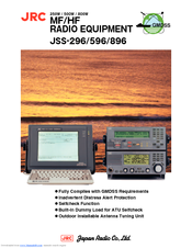
JRC JSS-596 - Brochure (3 pages)
250W / 500W / 800W MF/HF RADIO EQUIPMENT
Brand:
JRC
| Category:
Marine Radio
| Size: 0.53 MB
Advertisement
Related Products
JRC JSS-896 -
JRC JHS-32A
JRC JSS-296 -
JRC JSS-2150 -
JRC JSS-2500
JRC JSS-2250
JRC JSS-2250N
JRC JSS-2500N
JRC JSS-2150N
JRC JST-100
JRC Categories
Water Filtration Systems
Marine Radar
Marine Equipment
Radio Parts
Receiver
More JRC Manuals
Login
Sign In
OR
Sign in with Facebook
Sign in with Google
Upload manual
Upload from disk
Upload from URL