Sign In
Upload
Manuals
Brands
Intel Manuals
Server
S5500BC
Intel S5500BC Manuals
Manuals and User Guides for Intel S5500BC. We have
5
Intel S5500BC manuals available for free PDF download: Product Specification, User Manual, Spares Parts List & Configuration Manual, Documentation Update, Quick Start User Manual
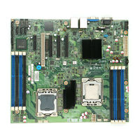
Intel S5500BC Product Specification (119 pages)
Server Board
Brand:
Intel
| Category:
Computer Hardware
| Size: 2.38 MB
Table of Contents
Table of Contents
3
Introduction
12
Server Board Use Disclaimer
12
Product Overview
13
Feature Set
13
Server Board Layout
15
Server Board Connector and Component Layout
15
Figure 1. Intel Server Board S5500BC Picture
15
Figure 2. Intel
16
Table 1. Board Layout Reference
16
Server Board Mechanical Drawing
17
Figure 3. Key Connector and LED Indicator Identification
17
Figure 4. Mounting Hole Location
18
Figure 5. Major Connector Pin-1 Locations
19
Figure 6. S5500BC Board Primary Side Keepouts
20
Figure 7. S5500BC Board PRIMARY SIDE CARD-SIDE KEEPOUT ZONE
21
Figure 8. Secondary Side Keepout -- Mounting Hole Keepout
22
Figure 9. Secondary Side Keepout - CPU Socket and Rubber Pad Keepout
23
Intel ® Light-Guided Diagnostic LED Locations
24
Light-Guided Diagnostic LED Reference
24
External I/O Connector Locations
25
Figure 10. Intel
25
Figure 11. External I/O Layout
25
Table 3. External I/O Layout Reference
25
Functional Architecture
26
Processor Sub-System
26
Figure 12. Functional Block Diagram
26
Intel ® Quickpath Interconnect (QPI)
27
Table 4. Intel ® Xeon ® Processor 5500 Series Feature Set Overview
27
Processor Population Rules
28
Figure 13. Intel ® IOH 5500 Chipset with Intel ® Quickpath Interconnect Block Diagram
28
Table 5. Mixed Processor Configurations
29
Multiple Processor Initialization
30
Turbo Mode
31
Simultaneous Multi-Threading
31
Enhanced Intel Speedstep Technology
31
Multi-Core Processor Support
32
Independent Loading Mechanism (ILM) Back Plate Design Support
32
Memory Sub-System
33
Integrated Memory Controller
33
Figure 14. ILM Backplate and URS
33
DIMM Population Requirements
34
Figure 15. DIMM Organization
34
Figure 16. Channel Slots Configuration
35
Memory Upgrade Guidelines
36
Table 6. DIMM Population Configurations
36
Support for Mixed-Speed Memory Modules
37
CPU Cores, QPI Links and DDR3 Channels Frequency Configuration
37
Memory RAS Features
37
Independent Channel Mode
38
Channel Mirroring Mode
38
Lockstep Channel Mode
38
Demand and Patrol Scrub
39
Intel I/O Hub (IOH) 5500 Chipset
39
Table 7. Intel IOH 5500 Chipset Features
39
PCI Express* Gen 2
40
Enterprise South Bridge Interface (ESI) Features
40
Controller Link (M-Link)
40
Management Engine (ME)
40
VT-D) (Rev. 2)
41
Intel ® 82801Jx I/O Controller Hub (ICH10R)
42
PCI and PCI Express* Interfaces
42
Serial ATA II Interface
43
Software RAID Support
43
Low Pin Count Interface (LPC)
44
Serial Bus (USB) Controller
44
Serial Peripheral Interface (SPI)
44
General Purpose Input/Output (GPIO)
44
Enhanced Power Management
44
System Management Interface
45
Real Time Clock (RTC)
45
Manageability
45
Unsupported Intel ICH10R Interfaces
45
Network Interface Controller (NIC)
46
Table 8. NIC Status LED
46
Intel ® 82574L Gbe PCI-E Network Controller
47
Intel ® 82567 Gigabit Network Connection Physical Layer Transceiver (PHY)
47
MAC Address Definition
47
Integrated Baseboard Management Controller
48
Integrated BMC Embedded LAN Channel
50
Figure 17. Integrated BMC Block Diagram
50
Video Support
51
Video Modes
51
Serial Ports
51
Floppy Disk Controller
51
Table 9. Video Modes
51
3.10 Keyboard and Mouse Support
52
3.11 Wake-Up Control
52
3.12 System Health Support
52
Platform Management
53
Figure 18. SMBUS Block Diagram
54
Feature Support
55
IPMI 2.0 Features
55
Non-IPMI Features
55
Advanced Management Feature Support
56
Enabling Advanced Management Features
56
Keyboard, Video, Mouse (KVM) Redirection
57
Media Redirection
57
Availability
58
Web Services for Management (WS-MAN)
58
Local Directory Authentication Protocol (LDAP)
58
Embedded Web Server
58
Console Redirection
59
Serial Configuration Settings
59
SOL, EMP and Console Redirection Use Case Model
59
Node Manager
60
Overview
60
Command Bridging
60
External Communications Link
61
Alerting
61
System Information Passed to ME and POST Complete Notification
61
ACPI Mode Notification
62
Persistence Across Boots
62
Power Management Bus (PMBUS)
62
Connector / Header Locations and Pin-Outs
63
Board Connectors
63
Power Connectors
63
Table 10. Board Connector Matrix
63
Table 11. EPS12V 2X12 Connector (J9B3)
64
Table 12. EPS12V 2X4 Connector (J7K1)
64
Riser Card Slot
65
Table 13. EPS12V 1X5 Connector (J9E1)
65
Table 14. Low-Profile PCI Riser Card Pin-Out (J3C1)
65
RMM3 Connector
66
Table 15. RMM3 Connector Pin-Out (J3C1)
66
SSI Front Panel Connector
67
I/O Connector Pin-Out Definition
67
VGA Connector
67
Table 16. Front Panel SSI Standard 24-Pin Connector Pin-Out (J9E2)
67
SATA II Connectors
68
Table 17. VGA Connector Pin-Out (J7A1)
68
Table 18. SATA Connector Pin-Out (J1B4, J1B3, J1A2, J1B1, J1B2, and J2B1)
68
Serial Port Connectors
69
USB and Gige Connector
69
Table 19. 9-Pin External Serial a Port Header Pin-Out (J8A1)
69
Table 20. Internal Serial B Port Header Pin-Out (J9A1)
69
Table 21. External USB and Gbe Connector Pin-Out (J5A1, J6A1)
70
Table 22. Internal USB Header Pin-Out (J1A3, J2A2)
70
Fan Headers
71
SGPIO Header
72
Chassis Intrusion Header
72
5.10 SMB Hot-Swap Backplane (HSBP) Header
72
Table 24. SGPIO Connector Pin-Out (J1C1)
72
Table 25. Chassis Intrusion Connector Pin-Out (J8B3)
72
Table 26. SMB HSBP Connector Pin-Out (J9B1)
72
5.11 SATA RAID Key Header
73
5.12 IPMB Header
73
Table 27. SATA Connector Pin-Out (J7B1)
73
Table 28. IPMB Connector Pin-Out (J8B1)
73
Jumper Block Settings
74
Figure 19. Jumper Blocks
74
Table 29. Jumper Block Matrix
74
Intel Light-Guided Diagnostics
76
5-Volt Standby LED
76
System ID and Status LED
76
DIMM Fault Leds
77
Table 30. System Status LED Indicator States
77
Fan Fault Leds
78
Post Code Diagnostic Leds
78
Table 31. DIMM Leds Indicator States
78
Table 32. Fan LED Indicator States
78
Power and Environmental Specifications
79
Intel ® Server Board S5500BC Design Specifications
79
Baseboard Power Requirements
79
Table 33. Server Board Design Specifications
79
Figure 20. Power Distribution Block Diagram
80
Power Requirements
81
8.2.2 Turn on no Load Operation
81
Grounding
81
Table 34. no Load Operating Range
81
Standby Outputs
82
Remote Sense
82
Voltage Regulation
82
Dynamic Loading
83
Capacitive Loading
83
Closed-Loop Stability
83
Table 35. Voltage Regulation Limits
83
Table 36. Transient Load Requirements
83
Table 37. Capacitive Loading Conditions
83
Common Mode Noise
84
Ripple / Noise
84
Soft Starting
84
Timing Requirements
84
Table 38. Ripple and Noise
84
Figure 21. Output Voltage Timing
85
Table 39. Output Voltage Timing
85
Table 40. Turn On/Off Timing
85
Residual Voltage Immunity in Standby Mode
86
Figure 22. Turn On/Off Timing (Power Supply Signals)
86
Regulatory and Certification Information
87
Product Regulatory Compliance
87
Product Safety Compliance
87
Product EMC Compliance - Class a Compliance
88
Certifications / Registrations / Declarations
88
Product Ecology Requirements
88
Product Regulatory Compliance Markings
90
9.3 Electromagnetic Compatibility Notices
92
FCC Verification Statement (USA)
92
ICES-003 (Canada)
93
Europe (CE Declaration of Conformity)
93
VCCI (Japan)
93
BSMI (Taiwan)
94
RRL (Korea)
94
CNCA (CCC-China)
94
Appendix A: Integration and Usage Tips
95
Appendix B: Sensor Tables
96
Table 41. Integrated BMC Core Sensors
97
Appendix C: POST Error Messages and Handling
105
Table 42. POST Error Messages and Handling
105
Table 43. POST Error Beep Codes
108
Appendix D: POST Code Diagnostic LED Decoder
110
Figure 23. Diagnostic LED Placement Diagram
110
Table 44. POST Progress Code LED Example
110
Table 45. Diagnostic LED POST Code Decoder
111
Appendix E: Intel Server System SR1630BC
114
Figure 24. 1U Intel ® Server System SR1630BC Overview
114
Appendix F: Supported Intel Server Chassis SC5650
115
Figure 25. 5U Intel Entry Server Chassis SC5650 Overview
115
Glossary
116
Reference Documents
119
Advertisement
Intel S5500BC User Manual (86 pages)
User Guide
Brand:
Intel
| Category:
Server Board
| Size: 4.53 MB
Table of Contents
About this Manual
5
Manual Organization
5
Additional Information and Software
6
Product Accessories
6
Preface
5
Important Safety Instructions
9
Warnings
11
Table of Contents
13
Safety Information
9
Chapter 1: Server Board Features
21
Figure 1. Intel ® Server Board S5500BC
21
Table 1. Intel ® Server Board S5500BC Feature Summary
22
Table 2. Configuration Jumper
25
Back Panel Connectors
27
Figure 4. Back Panel Connectors
27
RAID Support
28
Table 3. NIC Leds
28
Hardware Requirements
29
Figure 5. DIMM Configuration Diagram
30
Figure 6. Channel Slots Configuration
31
Hard Disk Drives
32
Before You Begin
33
Connector and Component Locations
23
Figure 2. Server Board Connector and Component Locations
23
Configuration Jumpers
25
Figure 3. Configuration Jumper Locations
25
Chapter 2: Hardware Installations and Upgrades
33
Optional Hardware
32
Power Supply
32
Installing and Removing Memory
33
Installing Dimms
33
Tools and Supplies Needed
33
Figure 7. Installing Memory
34
Figure 8. Lifting the Load Lever
35
Installing or Replacing the Processor
35
Installing the Processor
35
Removing Dimms
34
Figure 10. Remove the Socket Protective Cover
36
Figure 11. Remove the Processor Protective Cover
36
Figure 9. Open the Load Plate
36
Figure 12. Installing the Processor
37
Figure 13. Close the Load Plate and Socket Lever
37
Figure 14. 2U Reference Heat Sink Assembly
38
Replacing a Processor
38
Figure 15. Removing the PCI Riser Assembly from the Server System
40
Installing a PCI Add-In Card
40
Figure 16. Installing a PCI Card in a Riser Card
41
Replacing the Backup Battery
42
Installing the Retention Mechanism(S) and Heat Sink(S)
37
Figure 17. Replacing the Backup Battery
43
Chapter 3: Server Utilities
45
If You Cannot Access Setup
45
Setup Menus
45
Starting Setup
45
Using the BIOS Setup Utility
45
Table 4. Setup Menu Key Use
46
Preparing for the Upgrade
47
Recording the Current Bios Settings
47
BIOS Recovery Mode and BIOS Flash Update
48
Recovering the BIOS
48
Upgrading the BIOS
47
Figure 18. BIOS Recovery Jumper
49
Clearing the Password
50
Figure 19. Password Recovery Jumper
50
Intel ® Server Board S5500BC User's Guide
50
Clearing the CMOS
51
Figure 20. CMOS Recovery Jumper
51
Resetting the System
53
System Boot Quiet Time
53
First Steps Checklist
54
Problems Following Initial System Installation
54
Confirming Loading of the Operating System
55
Hardware Diagnostic Testing
55
Verifying Proper Operation of Key System Lights
55
Power Light Does Not Light
56
Specific Problems and Corrective Actions
56
Characters Are Distorted or Incorrect
57
No Characters Display on Screen
57
CD-ROM Drive or DVD-ROM Drive Activity Light Does Not Light
58
Drive Activity Light Does Not Light
58
System Cooling Fans Do Not Rotate Properly
58
Cannot Connect to a Server
59
Problems with Network
59
Problems with Application Software that Ran Correctly Earlier
60
Problems with Newly Installed Application Software
60
System Boots When Installing PCI Card
60
Devices Are Not Recognized under Device Manager
61
System
61
LED Information
62
BIOS POST Beep Codes
63
Chapter 4: Troubleshooting
53
Table 5. POST Error Beep
63
Appendix A: Regulatory and Compliance Information
65
Product EMC Compliance - Class a Compliance
65
Product Regulatory Compliance
65
Product Safety Compliance
65
Certifications / Registrations / Declarations
66
Important Note
66
Product Regulatory Compliance Markings
66
Electromagnetic Compatibility Notices
68
Fcc (Usa)
68
Europe (CE Declaration of Conformity)
69
Industry Canada (ICES-003)
69
Korean Compliance
69
Taiwan Declaration of Conformity (BSMI)
69
Figure 21. Diagnostic LED Placement Diagram
71
Appendix B: LED Decoder
71
Appendix C: Getting Help
71
Table 6. Diagnostic LED Placement Diagram
71
Table 7. POST Progress Code LED
72
Table 8. Diagnostic LED POST Code
72
Warranty Information
79
Intel S5500BC Documentation Update (19 pages)
S5500BC_SR1630BC_SC5650BCDP_MSU_2011_09.
Brand:
Intel
| Category:
Server
| Size: 0.4 MB
Table of Contents
Revision History
2
Table of Contents
4
Preface
7
Summary Tables of Changes
8
Errata
10
Errors Are Reported During the Installation of Suse SLES 10 EM64T
10
Hyper Threading Cannot be Disabled in BIOS Setup
10
A Critical Interrupt Is Logged in the System Event Log (SEL) When Installing Suse SLES 10 32 Bit
10
Serial Console Mode May Display Extra Text or Intermingled Text
10
The PXE Boot Option Is Missing in BIOS Setup
11
Fans May Boost Temporarily When BMC Is under Load
11
Extra Events May be Seen in the SEL During System Reset
11
BIOS Setup May Report an Incorrect Firmware Version
12
Excessive Time to Enter or Exit EFI Shell When AHCI Is Enabled in BIOS Revision R0037
12
Must Use Software Package with BIOS36/FW36/FRUSDR13 or Later When Using 4GB Memory Modules in the SR1630BC
12
Serial over LAN (SOL) will Not Automatically Enable Console Redirection When Console Redirection Is Disabled in BIOS Setup
13
Under Red Hat* Linux 5.3 When in SATA MODE to Compatibility Mode the Installation Process May Take over an Hour
13
Excessive Logs Get Reported after System Reboot When Running Suse* Linux 10, with Service Pack 2 X86
14
System Hang May Occur During FRU/SDR Update Process with the Intel® Server System SR1630BC
14
System May Not Configure to CLTT Mode When Using Unbuffered Memory with Thermal Sensors
14
Clearing BIOS CMOS in BIOS Revision R0042 May Return an Invalid Date
14
Intel® Active System Console (IASC) 3.5.1 and 3.5.2 May Fail to Detect Status of Memory Voltage Sensors
15
Suse* SLES11 Kernel May Halt for 60~150Seconds During Installation with Default BIOS Setting
15
BIOS Setup May Report Inaccurate HSC FW Revision
16
System Fail in Booting into Suse* SLES11 32 Bit Xen Kernel When Memory Size >=4GB under SW RAID Mode
16
System with BIOS Revision R0054 May Hang When Adaptec* 5405 or 5805 RAID Card Installed
16
I/8I and LSI* 20320-R SCSI Card Installed
17
System May Go to Efi First Instead of Hardware Raid Configuration Setup Page
17
System May Get Blue Screen on Display During the Installation of Windows Server 2008* R2 under UEFI Mode
17
Documentation Changes
19
Updating Information for Usable/Accessible Memory for BMC Video/Graphic Display Functions for the Onboard Server Engine* LLC Pilot II* Video Controller
19
Advertisement
Intel S5500BC Spares Parts List & Configuration Manual (22 pages)
Server Board, chassis and system
Brand:
Intel
| Category:
Server
| Size: 0.3 MB
Table of Contents
Change History
2
Table of Contents
3
Contents
3
Production Configurations
4
Production Board
4
Production Chassis
4
Production Integrated 1U System
5
Production Order Codes
7
Production Board
7
Production Board Accessories
7
Production Chassis
8
Production Chassis Spares and Accessories
9
Production System SR1630BC
13
Production System SR1630BC Accessory
14
Production System SR1630BC Spares
14
Production RAID Accessories (Not Including BBU)
16
Production RAID Controller
16
Intel® System Management Software - (Upgrade Skus)
17
Intel® System Management Software - Upgrade Order Codes
18
Production Intel Xeon Processor 5500 Series
20
Production Intel Thermal Solution STS100 Series
21
Intel S5500BC Quick Start User Manual (1 page)
Quick Start Guide
Brand:
Intel
| Category:
Server Board
| Size: 1.01 MB
Advertisement
Related Products
Intel S5520URT
Intel S5000PAL
Intel SR2500ALBRP - Server System - 0 MB RAM
Intel SBXL52 - Server Compute Blade
Intel SR1500ALSAS - Server System - 0 MB RAM
Intel SR1530HCL - Server System - 0 MB RAM
Intel SR1530HCLSRNA - Server System - 0 MB RAM
Intel SERVER SYSTEM SR2500AL
Intel S2600CW
Intel SBCE
Intel Categories
Motherboard
Computer Hardware
Server
Server Board
Desktop
More Intel Manuals
Login
Sign In
OR
Sign in with Facebook
Sign in with Google
Upload manual
Upload from disk
Upload from URL