Sign In
Upload
Manuals
Brands
IBM Manuals
Control Unit
3274 51C
IBM 3274 51C Manuals
Manuals and User Guides for IBM 3274 51C. We have
1
IBM 3274 51C manual available for free PDF download: Maintenance Information
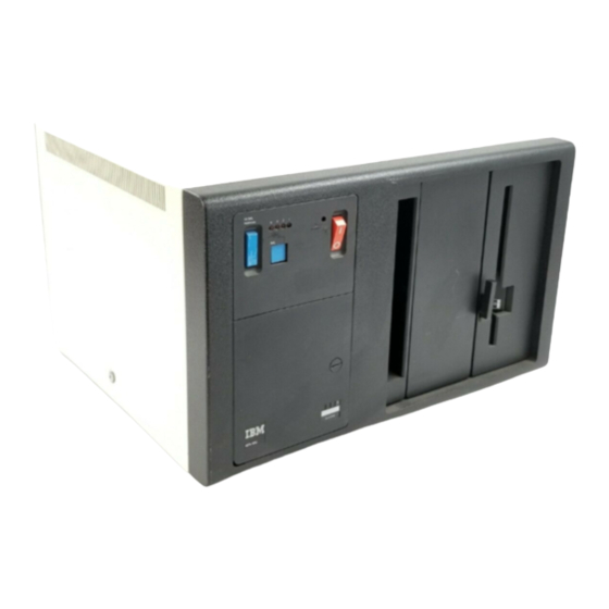
IBM 3274 51C Maintenance Information (358 pages)
Brand:
IBM
| Category:
Control Unit
| Size: 14.29 MB
Table of Contents
Table of Contents
2
Chapter Introduction 1.1 General
6
Maintenance Approach
6
Field Replaceable Unit (FRU) Locations
7
0IA-Al Logic Board
7
Card Numbers
7
IML Options
7
Machine Model Number
7
Operator Panel
7
Indicators
8
Chapter 2. Subsystem Problem Isolation Procedure
14
Step 1 Using the Isolation Procedure
14
Step 2 Power Test
14
Step 3 Bus Test
14
Step 4 Internal Tests
15
Operational Indicators
15
Control Storage Card Layouts
19
Step 5 Device Adapters - Driver/Receiver
20
Step 6 Display Symbols (Category a Only)
24
Step 8 Host Attachment
27
Step 9 Voltage Checks
27
Step 10 Verification Test
27
Step 11 Last Option
27
Symptom Repair List
27
Chapter 3 . Maintenance Analysis Procedures (Maps)3-1
28
General
28
MAP A20, Control Logic Failure
28
Map A40 Diskette Failure
38
MAP A50, Type a Adapter Failure Code
45
Map A100 Machine Checkout
49
Turning
63
Chapter 4. Removal and Replacement Procedures
81
Machine Access - Cover Removal/Ce Manuals
82
Machine Access, Cover
82
Machine Access - Board/Tsr Supply
83
Card Removal and Replacement
84
Internal Cable/Connector, Removal and Replacement
84
Prime Power Box
85
Prime Power Box, Removal and Replacement
85
Prime Power Transformer
86
Fan Assembly, Removal and Replacement
87
Prime Power Transformer, Removal and Replacement
86
Fan Assembly
87
Diode Assembly, Removal and Replacement
88
Input Filter Capacitor, Removal and Replacement
89
TSR Power Supply, Removal and Replacement
90
TSR Power Supply
90
I/O Panel - Driver/Receiver, Removal and Replacement
91
I/O Panel, Driver/Receiver Card
91
Diskette Drive, Removal and Replacement
92
Line Plate Card, Removal and Replacement
93
Operator Panel/Indicator Card
94
Operator Panel/Indicator Card, Removal and Replacement
94
Operator Panel Switches, Removal and Replacement
96
Operator Panel Switches
97
3274 Model SIC BSC
98
3274 Models SIC and 52C Modes/Speeds
98
Chapter S. Communications Reference Data
98
Communications Facilities
98
Eia
98
Integrated Modem (1200 Bps)
101
Integrated Modem (1200 Bps) Wrap
101
Integrated Modems (2400, 4800, and 9600 Bps)
101
Loop
101
Switched
101
Communications Line Flow, EIA
102
Communications Line Flow, DDS Adapter
105
Communications Line Flow, Loop
106
CBS Data Coupler - U.S. and Canada
109
Wrap Test
110
Wrap Test Without Attached Modem
110
9600-Bps Integrated Modem
111
Line Attachments
111
Loop Indicators
111
Loop Wrap Test
111
Multipoint Network Operating Speed
111
Point-To-Point Network Operating Speed
111
Communications Line Flow, 2400-Bps, 4800-Bps, and 9600-Bps Nonswitched Integrated Modems (Model SIC) for U.S., Canada, and World Trade Countries
112
2400-,4800-, 9600-Bps Integrated Modem Diagnostics
115
ALT2 Self-Test
115
Integrated Modem Failure
115
Operate Indicator
115
Self-Test/Wrap Test
115
Signal Quality
115
Speed Control Backup
115
Test Results
116
ALT2/IML Modem Wrap Test
119
And Canada
119
Countries
119
Other Countries
119
Procedure to Follow if IML Test 0111 Is Flashing
119
Test Alarm Card (TAC) Extended Diagnostic
119
Transmit Level Switch Settings
120
2400-,4800-, and 9600-Bps Integrated Modem
122
Board Wiring Options
122
Card Wiring Options
122
Carrier Detect Sensitivity (Normally Not Adjusted)
122
Clear-To-Send Delay (Normally Not Adjusted)
122
Continuous/Noncontinuous Carrier (Normally Not Adjusted)
122
Multipoint)
122
Transmission Pre-Emphasis for 2400-Bps
122
3274 System Grounding
122
Board Wiring for the Various Teleprocessing Attachment Configurations
122
Top Card Connector Pin Locations
124
Pluggable ROS Removal Tool
126
3290 Address Configuration
128
Configuration Support D
129
Configuration Support T
129
Battery Power Supply Check
130
Chapter 6. 3274 Encrypt/Decrypt Feature
130
Featuredescription
130
Encrypt/Decrypt Failures
130
Feature Components
130
IML Display Indications
130
Procedure for Encrypt/Decrypt Battery Replacement
131
Entering the Terminal Master Key
132
Appendix E. 31SD Diskette Drive Maintenance E-L
133
Verifying the Terminal Master Key
133
Encrypt/Decrypt Feature Test
134
Appendix F. 5 Ltd Diskette Drive Maintenance F-1
136
Chapter 7. Response Time Monitor
136
Feature Description
136
IML Testing
136
Microcode Support
136
Appendix A. Locations
139
Card Connector
139
Card
139
Locations
145
Card Location Chart
151
Transformer Input and Fan Voltage Wiring
155
N-Sw and N-Sw-SNBU, U.S. and Canada
164
N-Sw, WT Except Canada
164
SW-AA/MA,'U.S. and Canada
164
N-Sw-SNBU-AA, WT Except Canada
168
Sw-AA, WT Except Canada
169
Operator Panel
186
Table of Contents
191
Chapter 1 Introduction
192
General Description
192
Diskette Description
193
Diskette Insertion and Removal
194
Maintenance
195
Electrical Characteristics
196
Machine Characteristics
196
Physical Characteristics
196
Environmental Characteristics
197
Machine Safety
197
Personal Safety
197
Safety
197
Diskette Drive Parts
199
Control Card Interface
202
Device Theory of Operation
202
Mechanicaloperation
204
Typical Device Operation
204
Read Data
208
Collet/Flat Spring Assembly
211
Collet/Flat Spring Removal
211
Maintenance
211
Collet/Flat Spring Replacement
212
Head/Carriage Assembly
213
Head/Carriage Pressure Pad Removal and
213
Replacement
213
Head/Carriage Adjustment
217
Head/Carriage Removal
219
Head/Carriage Replacement
219
Head Load Solenoid and Bail
223
Solenoid and Bail Service Check
223
Head Gap Service Check
225
Head Gap Adjustment
225
Bail Adjustment
225
Bail Removal
227
Bail Replacement
227
Solenoid and Idler Removal
227
Solenoid and Idler Replacement
227
AC Drive Parts
230
Drive Motor Removal
230
Drive Motor Replacement
230
Capacitor Removal
230
Capacitor Replacement
230
Drive Fan and Pulley Assembly Removal
232
Drive Fan and Pulley Assembly Replacement
232
Stepper Drive Parts
232
Stepper Motor Removal
232
Stepper Motor Replacement
232
Drive Band Removal
234
Drive Band Service Check
234
Drive Band Adjustment
234
Stepper Pulley and Clamp Removal
234
Stepper Pulley and Clamp Replacement
234
Drive Band Replacement
235
Diskette Speed Service Check
237
LED Output Service Check
239
LED Removal
239
LED Replacement
240
PTX Amplifier Service Check
240
Control Card Removal
242
Diskette Drive Control Card
242
PTX Removal
242
PTX Replacement
242
Control Card Replacement
242
Control Card Test Pins and Connector Pins
242
Diskette Drive
303
Advertisement
Advertisement
Related Products
IBM 3274 52C
IBM 3274
IBM 3279 2A
IBM 3278-3
IBM 3278-4
IBM 3278-5
IBM 3279
IBM 1620
IBM 1620-2 DPS
IBM 1626
IBM Categories
Server
Desktop
Storage
Laptop
Monitor
More IBM Manuals
Login
Sign In
OR
Sign in with Facebook
Sign in with Google
Upload manual
Upload from disk
Upload from URL