Sign In
Upload
Manuals
Brands
HP Manuals
Measuring Instruments
HP 8566B
HP HP 8566B Manuals
Manuals and User Guides for HP HP 8566B. We have
2
HP HP 8566B manuals available for free PDF download: Adjustment Manual, Installation And Verification Manual
HP HP 8566B Adjustment Manual (405 pages)
Spectrum Analyzer Performance Tests and Adjustments Manua
Brand:
HP
| Category:
Measuring Instruments
| Size: 6.45 MB
Table of Contents
Table of Contents
8
General Information Introduction
17
Instruments Covered by this Manual
18
Operation Verification
18
Option 462 Instruments
18
Option 857 Instruments
18
L-L. Service Accessories, HP Part Number 08566-60001
25
Introduction
26
Verification of Specifications
26
Calibration Cycle
27
Equipment Required
28
Performance Test Record
28
L. Center Frequency Test Setup
29
Center Frequency Readout Accuracy Test
30
Center Frequency Accuracy Measurement
31
Center Frequency Readout Accuracy
32
Narrow Span Test Setup
33
Frequency Span Accuracy Test
34
Narrow Span Accuracy
34
Wide Span Test Setup
35
Wide Span Accuracy
36
4-L. 6 Db Resolution Bandwidth Accuracy
37
Resolution Bandwidth Accuracy Test
38
Resolution Bandwidth Measurement
38
Bandwidth Accuracy
38
Resolution Bandwidth Selectivity Test
40
Db Bandwidth Measurement
40
Resolution Bandwidth Selectivity
41
Resolution Bandwidth Switching Uncertainty Test
42
Db Resolution Bandwidth Accuracy
42
Db Resolution Bandwidth Selectivity
42
Bandwidth Switching Uncertainty
42
Bandwidth Switching Uncertainty Measurement
43
Log Scale Switching Uncertainty Test
44
Log Scale Switching Uncertainty Measurement
45
IF Gain Uncertainty Test
46
IF Gain Uncertainty Test Setup
46
IF Gain Uncertainty Measurement
48
IF Gain Uncertainty, 10 Db Steps
48
IF Gain Uncertainty, 2 Db Steps
49
Amplitude Fidelity Test
52
Amplitude Fidelity Measurement
54
Log Scale Fidelity
54
Linear Amplitude Fidelity
55
Calibrator Amplitude Accuracy Test
56
Frequency Response Test Setup
58
Table of Contents
59
Frequency Response Measurement (1 Khz to 100 Khz)
60
Frequency Response Test Setup (100 Khz to 60 Mhz)
61
Frequency Response Measurement (100 Khz to 4 Mhz)
62
Frequency Response Measurement (4 Mhz to 60 Mhz)
63
Frequency Response Measurement (60 Mhz to 2.5 Ghz)
66
Frequency Response Test
70
Sweep Time Accuracy Test
72
Sweep Time Accuracy
73
Noise Sidebands Test
74
Noise Sidebands Test Setup
75
Noise Sidebands Measurement
76
Line-Related Sidebands Test
78
Line Related Sidebands Test Setup
78
Line-Related Sidebands Measurement
80
Average Noise Level Test
83
Average Noise Level Measurement
84
Average Noise Level
85
Residual Responses Test
86
Residual Responses Measurement
87
Harmonic and Intermodulation Distortion Test
90
Harmonic Distortion Test Setup
91
Intermodulation Distortion Test Setup
94
Third Order Intermodulation Products
96
TO1 Measurement Settings
97
Image and Out-Of-Band Response
98
Image, Multiple, and out of Band Responses Test
100
Multiple Responses
101
Gain Compression Test
102
Gain Compression Test Setup
102
St lo Output Amplitude Test
106
1St lo Output Amplitude Test Setup
106
Sweep + Tune out Accuracy Test Setup
107
Sweep + Tune out Accuracy Test
108
Fast Sweep Time Accuracy (~20 Ms) Test Setup
109
Fast Sweep Time Accuracy Test (~20 Ms)
110
Fast Sweep Time Measurement (~20 Ms)
110
Set Function Generator Controls as Follows
110
Function
110
Offset
110
Sym
110
Trigger Phase
110
Modulation
110
Frequency Reference Error Test
112
Frequency Reference Test Setup
113
Test 1. Center Frequency Readout Accuracy
115
Test 2. Frequency Span Accuracy Test
116
Test 3. Resolution Bandwidth Accuracy Test
117
Test 4. Resolution Bandwidth Selectivity
118
Test 6. Log Scale Switching Uncertainty Test
120
Test 7. if Gain Uncertainty
122
Test 9. Calibrator Amplitude Accuracy
125
Test 10. Frequency Response Test
126
Frequency Response (Flatness)
127
Test 11. Sweep Time Accuracy
128
Sweep Time Accuracy, Sweep Times 220 Ms
128
Test 13. Line-Related Sidebands
130
Test 15. Residual Responses
132
Test 17. Image, Multiple, and Out-Of-Band Responses
134
Test 18. Gain Compression
136
Test 19. 1St lo Output Amplitude
137
Test 20. Sweep + Tune out Accuracy
138
Test 22. Frequency Reference Error Test
140
Adjustments Introduction
141
Adjustments
141
Adjustment Tools
142
Equipment Required
142
Safety Considerations
142
Warning
142
Factory-Selected Components
143
Location of Test Points and Adjustments
143
Related Adjustments
143
Adjustable Components
145
Factory-Selected Components
155
Standard Value Replacement Capacitors
160
Standard Value Replacement 0.125 Resistors
161
Standard Value Replacement 0.5 Resistors
163
Low-Voltage Power Supply Adjustments
165
IF-Display Section Adjustments (SN 3001A and Below)
166
IF-Display Section Adjustments (SN 3004A and Above)
167
High-Voltage Adjustment (SN 3001A and Below)
171
High Voltage Adjustment Setup
172
Location of High Voltage Adjustments
173
Location of Label and Test Point
174
Location of Ala Components
176
CRT Cut-Off Voltage
177
High-Voltage Adjustment (SN 3004A and Above)
181
High Voltage Adjustment Setup
182
Location of High Voltage Adjustments
183
Discharging the CRT Post-Accelerator Cable
187
Adjustments
188
Preliminary Display Adjustments (SN 3001A and Below)
188
Preliminary Display Adjustments Setup
189
Ala2, Ala4, and Ala Adjustment Locations
190
Location of Ala2, Ala4, Ala5, and A3A2
190
Composite X Deflection Waveform
192
Rise and Fall Times and Overshoot Adjustment
193
Preliminary Display Adjustments (SN 3004A and Above)
196
Preliminary Display Adjustments Setup
197
Ala Adjustment Locations
198
Location of Ala and A3A2
198
Composite X Deflection Waveform
200
5OV,, Signal
202
Below)
203
Final Display Adjustments (SN 3001A and Below)
203
Initial Adjustment Positions
203
Location of Final Display Adjustments on Ala2, Ala4
204
Final Display Adjustments (SN 3004A and Above)
205
Final Display Adjustments Setup
205
Location of Final Display Adjustments on Ala
206
Initial Adjustment Positions
206
Log Amplifier Adjustments
209
Log Amplifier Adjustments Setup
209
Location of Log Amplifier Adjustments
210
Video Processor Adjustments
213
Video Processor Adjustments Setup
213
Location of Video Processor Adjustments
214
Location of Center, Symmetry, and 10 Mhz Amplitude
218
Location of 3 Mhz Peak Adjustments
220
Mhz Bandwidth Filter Adjustments
222
Mhz Bandwidth Filter Adjustments Setup
222
Location of A4A4 21.4 Mhz LC Filter Adjustments
223
Location of A4A4 21.4 Mhz Crystal Filter Adjustments
224
Location of A4A8 21.4 Mhz LC Filter and Attenuation
225
Location of A4A8 21.4 Mhz Crystal Filter Adjustments
226
Mhz Bandwidth Filter Adjustments
228
Db Bandwidth Adjustments
229
Location of 3 Db Bandwidth Adjustments
230
Step Gain and 18.4 Mhz Local Oscillator Adjustments
234
Step Gain and 18.4 Mhz Local Oscillator Adjustments
235
Location of if Gain Adjustment
236
Location of 10 Db Gain Step Adjustments
237
Location of .L Db Gain Step, 18.4 Mhz LO, and + 1OV
238
Down/Up Converter Adjustments
240
Down/Up Converter Adjustments Setup
240
Location of Down/Up Converter Adjustments
241
Mhz Standard Adjustment (SN 2637A and Below)
244
Mhz Frequency Standard Adjustments Setup
245
Location of 10 Mhz Standard Adjustments
247
Mhz Standard Adjustment (SN 2728A and Above)
248
Mhz Frequency Standard Adjustments Setup
249
Location of 10 Mhz Standard Adjustments
252
Sweep, DAC, and Main Coil Driver Adjustments
253
Sweep and DAC Adjustments Setup
254
OV to + 1OV Sweep Ramp at A16TP3
255
Location of Sweep and DAC Adjustments
256
Improperly Adjusted DC Levels between Sweep Ramps
257
Properly Adjusted DC Levels between Sweep Ramps
257
YTO Main Coil Driver Adjustments Setup
260
Location of YTO Main Coil Driver Adjustments
261
Mhz VCXO Adjustment Setup
266
Location of 100 Mhz VCXO Adjustments
267
Mhz VCXO Adjustments
268
Typical Tuning Range of A7A2 100 Mhz VCXO
268
Standard Values for A7A2L4
268
Limits for 100 Mhz Harmonics
270
Selection Chart for Attenuator Resistors
270
Resistor Values
271
MN Loop Adjustments
272
M/N Loop Adjustments
272
M/N Loop Adjustment Setup
272
Location of PLL Adjustments
273
YTO Loop Adjustments
275
YTO Loop Adjustment Setup
276
Location of Assemblies, Cables, and Test Points
276
All YTO Loop Service Position
277
Typical YTO Loop Swept Frequency Response at Allal
279
Waveform
281
Sampler Waveform at Alla5Tpl
282
Power Level of Fundamental Signal
284
30 Loop Phase Lock Adjustments
286
Tuning the if out Fundamental
284
PLL Adjustment Setup
287
Location of Plll Adjustments
289
Location of PLL2 Adjustments
294
Location of PLL3 Adjustments
296
Standard Values for Aloa4C49
297
RF Module Phase Lock Adjustments
300
Location of RF Module Phase Lock Adjustments
301
RF Module Phase Lock Adjustments Setup
301
A Sampler Balance Adjustment Waveform
304
CAL Output Adjustment
306
Cal Output Adjustment Setup
306
Location of CAL OUTPUT Adjustment
307
CAL OUTPUT Harmonics
308
Last Converter Adjustments
309
Last Converter Adjustments Setup
310
Location of Last Converter Adjustments
311
1. Frequency Response Adjustments
314
Frequency Bands
314
Frequency Response Preliminary Adjustments Setup
316
Location of Frequency Response Adjustments
317
Frequency Response Adjustments Setup (10 Mhz to
319
Typical Coarse Frequency Response (10 Mhz - 2.5 Ghz)
321
Typical Frequency Response (10 Mhz - 2.5 Ghz)
322
Frequency Response Adjustments
326
Typical Coarse Frequency Response (2 Ghz - 5.8 Ghz)
327
Typical Frequency Response (2.0 Ghz - 5.8 Ghz)
328
Typical Coarse Frequency Response (5.8 Ghz -
331
Preselector Delay Compensation DAC Values
342
Analog-To-Digital Converter Adjustments
346
Track and Hold Adjustments
349
Digital Storage Display Adjustments
352
Press (CHAN_)
354
Channel 1
354
Amplitude Scale
354
Offset
354
Coupling
354
Source
354
Set the Oscilloscope Controls as Follows
354
Sample and Hold Balance Adjustment Waveforms
355
Waveform before Adjustment
355
Press (DISPLAY_)
356
Press
357
Low-Noise DC Supply
358
Parts for Low-Noise DC Supply
358
Crystal Filter Bypass Network Configuration
359
Introduction
360
Db Resolution Bandwidth Selectivity Test
360
Db Resolution Bandwidth Accuracy Test
362
Impulse Bandwidth Test Setup
363
Impulse and Resolution Bandwidth Accuracy Test
365
Sweep Time
366
Db Resolution Bandwidth Measurement
367
Db Bandwidth Measurement
370
Db Resolution Bandwidth Selectivity Test
371
Impulse and Resolution Bandwidth Selectivity Test
372
Db Bandwidth Measurement
373
Impulse and Resolution Bandwidth Switching Uncertainty Test
376
Bandwidth Switching Uncertainty Measurement
376
Test 3. Impulse and Resolution Bandwidth Accuracy Test (P/O 'Ihble 2-24, Performance Test Record)
378
Test 4. 6 Db Resolution Bandwidth Selectivity
380
Test 5. Impulse and Resolution Bandwidth Switching Uncertainty (P/O 'Ihble 2-24, Performace Test Record)
382
Db Resolution Bandwidth Adjustments
383
Location of Bandwidth Adjustments
384
Impulse Bandwidth Adjustments
386
Location of Bandwidth Adjustments
387
Option 857 Introduction
389
Option 857 Amplitude Fidelity Performance Test
391
Performance Test Record
394
Test 8. Option 857 Amplitude Fidelity
395
Linear Amplitude Fidelity
396
6-L
398
RF Section Figure Index
398
RF Section, Front View
400
RF Section, Bottom View
401
IF Section, Top View (SN 3001A and Below)
402
IF Section, 'Ibp View (SN 3004A and Above)
403
IF Section, Front View
404
IF Section, Bottom View
405
Advertisement
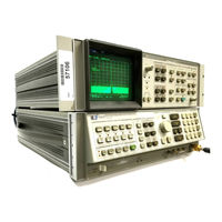
HP HP 8566B Installation And Verification Manual (114 pages)
Spectrum Analyzer, Includes Option 400, Option 462, and Option 857
Brand:
HP
| Category:
Measuring Instruments
| Size: 1.18 MB
Table of Contents
Table of Contents
7
1 General Information What You'll Find in this Chapter
13
Introducing the HP 8566B
13
Safety
14
Accessories Supplied
14
Accessories Available
17
Options
18
Instruments Covered by this Manual
19
Serial Numbers
19
Calibration Cycle
20
HP-IB Address Selection
20
Bench Operation
20
Electrostatic Discharge Information
21
Static-Safe Accessories
22
Routine Maintenance
23
Cleaning the Display
23
Cleaning the RF Section's Fan Filter
24
Replacing the RF Section's Battery
24
Location of Al5 Controller Assembly
25
Ordering Information
28
Direct Mail Order System
28
Direct Phone-Order System
28
Returning the Instrument for Service
29
Service Lags
29
Original Packaging
29
Service Tags
29
Other Packaging
30
Sales and Service Offices
32
2 Instailation
34
What You'll Find in this Chapter
34
Safety
34
Preparation for Use
35
Initial Inspection
35
Operating Environment
36
Power Requirements
36
To Install Standard Instruments
37
Voltage Selector Board and Fuse
38
Removing the Handles and Trim
40
Removing the Information-Card Tray
41
Voltage Selector Board and Fuse
42
Removing the Handles and Trim
44
Removing the Information-Card Tray
45
Voltage Selector Board and Fuse
47
From the Front Panel
51
From the HP-IB Bus
51
From the HP-IB Address Switch
51
To Set the HP-IB Address
51
Address Switch (Shown in Factory Preset Position)
53
Address Switch Set to
54
3 Specifications Introduction
56
Frequency
56
Measurement Range
56
Displayed Values
56
Center Frequency
56
Frequency Span
57
Resolution
58
Resolution Bandwidth
58
Resolution Bandwidth (Option 462 Impulse Bandwidth)
58
Bandwidth Shape
59
Spectral Purity
59
Amplitude
60
Measurement Range
60
Displayed Values
60
Scale
60
Accuracy
61
Reference Lines Accuracy
61
Dynamic Range
61
Spurious Responses
61
Image, Multiple, and Out-Of-Band Responses
62
Displayed Average Noise Level (Sensitivity)
63
Gain Compression
63
Residual Responses
63
Specified Average Displayed Noise Level, 2.0 Ghz to
64
Amplitude Uncertainty
65
Marker
68
Sweep
69
Inputs
69
If Input
69
Outputs
70
Cal Output
70
1Stlooutput
70
Sweep + Tune Output
70
Options
71
400 Hz Power Line Frequency Operation Option
71
General
72
HP-IB Interface Functions
72
Environmental
72
Altitude
72
Temperature
72
Power Requirements
72
Humidity
72
Operation
72
Storage
72
X-Rays
72
Warm-Up Time
74
Operation
74
Weight
74
Dimensions
75
Instrument Dimensions with Handles
75
Instrument Dimensions Without Handles
75
4 Performance Characteristics
76
Frequency
76
Resolution
76
Spectral Purity
76
Noise Sidebands
76
Power-Line Related Sidebands
76
Offset from Carrier
77
Single Sideband Noise Normalized to 1 Hz BW Versus
77
Stability
78
Drift
78
Residual FM
78
Typical SSB Noise at 5.0 Ghz Center Frequency
78
Amplitude
79
Third Order Intermodulation Distortion
79
Third Order Intercept (TOI)
79
Synthesis-Related Spurious Sidebands
80
Input Attenuator Uncertainties
80
RF Gain Uncertainty
80
Inputs
81
If Input
81
Rf Input
81
Video Inp
82
If Inp
82
Ext Trigger
82
Freqreferenceext
83
Outputs
83
Display Outputs
83
Recorder Outputs
83
Sweep
83
Video
84
Penlift
84
21.4 Mhz if OUTPUT
84
Freq Reference Int
84
10Mhzout
84
Video out
85
If out
85
If Output
85
General
85
Acoustic Noise Emission/Geraeuschemession
85
Function Descriptions
86
Sweep
86
Marker
86
Sweep Time
86
Video Bandwidth
86
Zero Frequency Span
86
Cathode Ray Tube
87
Instrument State Storage
87
Remote Operation
87
Equipment Connections
92
Program Loading
93
Program Operation
94
HP-Ibaddresses
95
Error Messages
96
IF Gain Uncertainty
98
Scale Fidelity (Log)
99
Scale Fidelity (Linear)
100
Log Scale Switching
101
Resolution Bandwidths
102
Impulse and Resolution Bandwidths
103
Line Related Sidebands
104
Average Noise Level
105
Residual Responses
106
Sweep + Tune out Accuracy
107
Second Harmonic Distortion
108
Frequency Span Accuracy
109
Gain Compression
110
Frequency Response
111
Third Order Intermodulation Distortion
112
St Looutput Power
114
Advertisement
Related Products
HP 8560A
HP 8568B
HP 85662A
HP 8562E
HP 8560E
HP 8560EC
HP 85688
HP 8565A
HP HP 8590 Series
HP 85108
HP Categories
Desktop
Laptop
Server
Monitor
Switch
More HP Manuals
Login
Sign In
OR
Sign in with Facebook
Sign in with Google
Upload manual
Upload from disk
Upload from URL