GE EntelliGuard G Manuals
Manuals and User Guides for GE EntelliGuard G. We have 6 GE EntelliGuard G manuals available for free PDF download: Installation, Operation And Maintenance Manual, Application Manual, Instructions Manual

GE EntelliGuard G Installation, Operation And Maintenance Manual (221 pages)
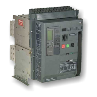
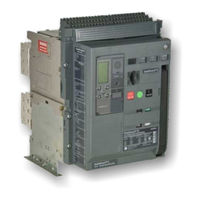
Power Circuit Breaker
Table of Contents
Advertisement
GE EntelliGuard G Installation, Operation And Maintenance Manual (252 pages)
Power Circuit Breaker
Brand: GE
|
Category: Circuit breakers
|
Size: 20.42 MB
Table of Contents

GE EntelliGuard G Application Manual (94 pages)
Brand: GE
|
Category: Circuit breakers
|
Size: 2.87 MB
Table of Contents
Advertisement
GE EntelliGuard G Installation, Operation And Maintenance Manual (43 pages)
Brand: GE
|
Category: Circuit breakers
|
Size: 2.49 MB
Table of Contents

GE EntelliGuard G Application Manual (62 pages)
Power Circuit Breaker
Brand: GE
|
Category: Circuit breakers
|
Size: 1.01 MB
Table of Contents

GE EntelliGuard G Instructions Manual (10 pages)
Test Cabinet (Inspection Box) for Testing Accessories on Manually and Electrically Operated Low Voltage Circuit Breakers
Brand: GE
|
Category: Test Equipment
|
Size: 0.25 MB
Table of Contents
Advertisement