Sign In
Upload
Manuals
Brands
Fluke Manuals
Measuring Instruments
96000 Series
Fluke 96000 Series Manuals
Manuals and User Guides for Fluke 96000 Series. We have
2
Fluke 96000 Series manuals available for free PDF download: Service Manual, Operator's Manual
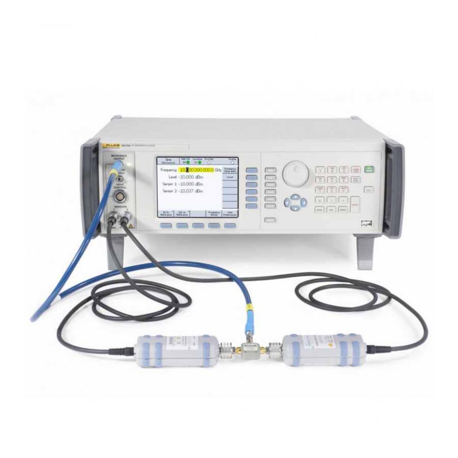
Fluke 96000 Series Operator's Manual (168 pages)
Brand:
Fluke
| Category:
Measuring Instruments
| Size: 5.16 MB
Table of Contents
Table of Contents
3
Introduction and Specifications
11
About the Manual
11
Contacting Fluke
11
Safety Information
12
Symbols
12
General Safety Summary
13
Prevent Instrument Damage
14
Instrument Description
16
Options and Accessories
17
Specifications
20
General Specifications (96040A and 96270A)
20
Frequency Reference Input/Output Specifications (96040A and 96270A)
21
Leveled Sine Specifications at Microwave Output (96270A)
23
Leveled Sine Specifications at Leveling Head Output (96040A and 96270A) and Microwave Output (96270A)
25
Modulation Specifications at Leveling Head Output (96040A and 96270A) and Microwave Output (96270A)
27
Frequency Sweep Specifications at Leveling Head Output (96040A and 96270A) and Microwave Output (96270A)
30
Frequency Counter Specifications
31
Power Meter Readout Specifications (96270A Only)
31
GPIB Command Emulation Mode Specifications
31
Prepare the Instrument for Operation
33
Introduction
33
Unpack and Inspect the Instrument
33
Store and Ship the Instrument
34
Power Considerations
35
Replace the Power Cord
35
Power-On Sequence
37
Power-On Self-Test
37
Power-On State
38
Leveling Head Connections (96270A and 96040A)
39
Microwave Output Connections (96270A)
40
Power Sensor Connections (96270A)
40
Install the Instrument in an Equipment Rack
40
Cooling Considerations
40
User-Initiated Self-Test
41
Running Self-Test
42
Review the Results
43
Operator Maintenance
44
Clean the Instrument
44
Clean the Air Filter
44
Replace the Line-Power Fuses
45
Firmware
47
Performance Test and Calibration
47
Local Operation
49
Introduction
49
Controls, Indicators, and Connectors
50
Leveling Head I/O Connectors
53
Microwave Output Connector (96270A)
53
Output Connector Status Indicators (96270A)
53
Sensor Connectors (96270A)
53
USB Storage Port (96270A)
54
STBY/OPER (Standby/Operate)
54
Function Keys
54
Signal Source Keys
55
MEAS (Measurements) Key
55
UNITS Key
55
SETUP Key
55
SIGNAL Key (96270)
57
Display
57
Data Fields
58
Soft Labels
59
Softkeys
59
Status Bar
60
Field Editor
60
Cursor Keys
60
Spin Wheel
61
Keypad
61
Alphanumeric Keys
61
ALPHA Key
61
NEXT CHAR Key
61
BKSP Key (Backspace)
61
SPACE Key
61
EXP Key (Exponent)
61
ENTER Key
62
Screen Controls and Indicators
62
Main RF Output Screens
62
Edit Modes - the Vertical Softkeys
63
Expanded Settings - the Horizontal Softkeys
67
Preferences Softkey
67
Offset Softkey
68
Toggle Offset Softkey
69
Offset (as Error) Softkey
69
Reference Softkeys
70
Reference off Softkey
71
Frequency and Level Track Main Softkeys
71
Rear-Panel Controls and Connectors
72
Power Block and Switch
73
IEEE 488 Connector
73
Reference Frequency Output Connector
73
Reference Frequency Input Connector
73
50 Mhz Frequency Counter, Modulation, Leveling and Frequency Pull Input Connector
74
300 Mhz Frequency Counter Input Connector (96270A)
77
Trigger I/O Connector
78
Instrument Operation
80
Before Starting
80
Set Global Preferences
80
Local or Remote Operation
81
GPIB Command Emulation
82
Select and Change the Address of a Command Emulation
83
Connect a Leveling Head to the Instrument
85
Connect a Leveling Head to a Unit under Test
87
Connect the Microwave Output to a Unit under Test (96270A)
89
Connect a Power Sensor to the Instrument (96270A)
91
Connect a Power Sensor to a Unit under Test (96270A 0Nly)
92
Save/Recall and Master Reset Function
93
Access the Memory Screen
93
Make a Memory Selection
94
Rename a Selection
94
Delete a Selection
94
Save an Instrument Setup
95
Save Settings for a Function
95
Recall Settings
95
Create an RF Output Signal
96
Output Signal Routing (96270A)
97
Leveled Sine Output Signal
100
Leveled Sine Preferences
100
Sensor Leveling and Sensor Leveling Preferences (96270A)
104
Rear Input Preferences
106
Display Layout Preferences (96270A)
107
Frequency Pull Preferences
108
Externally Leveled Sine Preferences
109
Enhanced Frequency Resolution
112
Reference Switching Preferences
113
Define the Leveled-Sine Output Signal
114
Apply an Offset to a Leveled-Sine Output Signal
117
Modulated Output Signal
118
Set Modulation Preferences
118
Define an Amplitude-Modulated Output Signal
119
Apply an Offset to an Amplitude-Modulated Output Signal
121
Create a Frequency-Modulated Output Signal
124
Apply an Offset to a Frequency-Modulated Output Signal
128
Phase-Modulated Output Signal
128
Apply an Offset to a Phase-Modulated Output Signal
132
Sweep Output Signal
132
Set the Sweep Preferences
133
Define a Swept-Frequency Output Signal
135
Narrow Range Locked Sweep
136
50 Mhz Frequency Counter (96040A)
138
300 Mhz Frequency Counter (96270A)
140
Power Meter Readout (96270A)
142
Power Meter Readout Selections
143
Power Readout Units
145
Set the Measurement Frequency
146
Set Power Sensor Preferences
147
Power Reading Averaging and Triggering
148
Relative Power Measurements
150
Change Units for Relative Power Measurements
151
Profiles (96270A)
151
Profiles Overview
151
Profile File Format and File Naming Requirements
154
Select and Apply Profiles
155
Import Profiles
158
Export Profiles
159
Profile Self Measure (Self-Characterization)
161
Measurement Integrity at High Signal Levels
166
Measurement Integrity at Low Signal Levels
166
Eliminate Interference from the Ether
167
Eliminate Interference from System Clocks - Common Mode and Ether Borne
167
Avoid Grounding RF Common on the Instrument
168
Verify the Level of an Interfering Signal
168
De-Tune the Interfering Signal
168
Advertisement
Fluke 96000 Series Service Manual (198 pages)
RF Reference Source
Brand:
Fluke
| Category:
Measuring Instruments
| Size: 9.06 MB
Table of Contents
Table of Contents
3
Introduction and Specifications
11
Introduction
11
Contact Fluke Calibration
12
Safety Information
12
Symbols
13
General Safety Summary
13
Prevent Instrument Damage
15
Specifications
17
General Specifications (96040A and 96270A)
17
Frequency Reference Input/Output Specifications (96040A and 96270A)
18
Leveled Sine Specifications at Microwave Output (96270A)
21
Leveled Sine Specifications at Leveling Head Output (96040A and 96270A) and Microwave Output (96270A)
23
Modulation Specifications at Leveling Head Output (96040A and 96270A) and Microwave Output (96270A)
25
Frequency Sweep Specifications at Leveling Head Output (96040A and 96270A) and Microwave Output (96270A)
28
Frequency Counter Specifications
29
Power Meter Readout Specifications (96270A Only)
29
GPIB Command Emulation Mode Specifications
29
Theory of Operation
31
Introduction
31
Overall Functional Description
31
User Interface
33
Frequency Synthesis
34
Amplitude Control
34
Frequency Modulation
35
Amplitude Modulation
35
Instrument Control
36
Power Supplies
36
Performance Tests
43
Introduction
43
Recommended Tools and Equipment
43
Performance Test
46
Reference Frequency Accuracy
47
Frequency Accuracy (96040A and 96270A)
48
Harmonics and Spurious Signal Content - Levelling Head (96040A and 96270A)
51
Phase Noise Test (96040A and 96270A, Optional)
54
Modulation Test-Leveling Head (96040A and 96270A, Optional)
56
Frequency Counter Accuracy (96040A and 96270A)
59
Level Accuracy - 50 Ω Leveling Head (96040A and 96270A)
60
Attenuation Accuracy - 50 Ω Leveling Head (Optional 96040A and 96270A)
73
Level Accuracy - 75 Ω Levelling Head (96040A and 96270A)
78
Attenuation Accuracy - 75 Ω Leveling Head (Optional, 96040A and 96270A)
91
VSWR Test - 75 Ω (Optional)
93
Microwave Output Level Accuracy (96270A, Optional Functional Test)
97
Microwave Output Frequency Accuracy (96270A Only)
108
Microwave Output Harmonics and Spurious Signal Content (96270A)
112
Modulation Test (96270A, Optional)
117
Calibration Adjustment
121
Introduction
121
Calibration Adjustments
121
Rear Panel Calibration Enable Switch
123
Reference Frequency Adjustment
123
Base Adjustment - Front Panel Head RF Output
124
Leveling Head Adjustment - 50 Ω
127
Leveling Head Adjustment - 75 Ω
130
Microwave Output Adjustment - with Low-Level Output Option Fitted
134
Microwave Output Adjustment - Low-Level Output Option Not Fitted
136
Microwave Output Flatness Characterization
138
Maintenance
139
Operator Maintenance
139
Clean the Product
139
Clean the Air Filter
140
Replace the Line-Power Fuses
140
Troubleshooting
142
Disassembly and Reassembly
142
Before You Start
143
Removing External Hardware Components
143
Handles
143
Top and Bottom Covers
144
Bottom Feet
144
Shields
144
Remove the Air Filter
144
Removing Major Assemblies
146
RF Output PCA
146
X 2W Coaxial Relays
148
Front Panel Assembly
148
Display and Keypad PCA
149
Digital PCA
150
27 Ghz Control PCA (96270A)
151
Synthesizer PCA
152
Fans
153
Rear Panel Assemblies
154
Interconnection PCA
155
Low Voltage Transformer
156
Power Supply PCA
156
Switch Mode Power Supply Module
157
Leveling Head Disassembly Procedure
158
Leveling Head Reassembly Procedure
159
Reassembling the Product
159
Safety Test
159
Running Self-Test
160
Review the Results
161
Interpreting the Results
163
Firmware Upgrade
164
Equipment Required for the Restore or Upgrade
164
Firmware Installation
165
Lists of Replaceable Parts
167
Introduction
167
How to Obtain Parts
167
Replaceable Parts Lists
168
A Performance Test Record
171
Advertisement
Related Products
Fluke 96
Fluke 96040A
Fluke 96270A
Fluke TRACKER 90100 Operators
Fluke 9190A
Fluke 9144
Fluke 9000A-006
Fluke 972B
Fluke 9172-B-R-156
Fluke 930
Fluke Categories
Measuring Instruments
Test Equipment
Multimeter
Thermometer
Laboratory Equipment
More Fluke Manuals
Login
Sign In
OR
Sign in with Facebook
Sign in with Google
Upload manual
Upload from disk
Upload from URL