Sign In
Upload
Manuals
Brands
Danfoss Manuals
Air Compressor
TGH Series
Danfoss TGH Series Manuals
Manuals and User Guides for Danfoss TGH Series. We have
1
Danfoss TGH Series manual available for free PDF download: Applications And Installation Manual
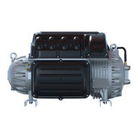
Danfoss TGH Series Applications And Installation Manual (114 pages)
Twin-Turbine Centrifugal Compressors
Brand:
Danfoss
| Category:
Air Compressor
| Size: 20.3 MB
Table of Contents
Table of Contents
3
Chapter 1.0 Introduction
11
Scope
11
Organization of this Manual
11
Document Symbols
11
Table 1-1 Application Manual Applicability
11
Table 1-2 Acronyms and Terms
13
Chapter 2.0 Overview of the TTS/TGS/TTH/TGH Compressor
17
TTS/TGS/TTH/TGH Compressor Nomenclature
17
Figure 2-1 Old Type Code to New Type Code Rev. D
17
Refrigerant Type
18
Table 2-1 Refrigerant Used with Turbocor Compressors
18
Figure 2-2 Compressor Nomenclature
18
Environment
19
Mains Plate Sealing
19
Configurations of the TTS/TGS/TTH/TGH Compressor Models
20
Compressor Module
20
Figure 2-3 Major Components
20
Chapter 3.0 Functional Description
21
Main Fluid Path
21
Figure 3-1 Compressor Fluid Path TGS230/TTS300
21
Motor Cooling
22
Figure 3-2 Compressor Fluid Path (TGS310, TTS350, TGS390, TGS490, TTS400, TGS520, and TTS700)
22
Figure 3-3 Compressor Cooling Circuit (TGS230 / TTS300)
23
Figure 3-4 Compressor Cooling Circuit (TTS300 Split-Cooling, TGS310, TTS350, TGS390, TGS490, TTS400, TT700, and TGS520)
23
Inlet Guide Vanes
24
Compressor Control Overview
24
Figure 3-5 Compressor Cooling Circuit (TGH285 / TTH375)
24
Figure 3-6 Compressor Control System Functional Block Diagram
25
Magnetic Bearing System
27
Table 3-1 Backplane Leds
27
Figure 3-7 Magnetic Bearing Configuration
27
Figure 3-8 Magnetic Bearing Control System
28
Chapter 4.0 Control Interface Wiring
29
Figure 4-1 Typical Control Wiring
29
Figure 4-2 Modbus Grounding Diagram
30
Table 4-1 Control Wiring Details
31
Table 4-2 Jumper Details
31
Control Wiring Connection Guidelines
32
Figure 4-3 I/O Wiring Specifications
32
Interface Cable
32
Compressor I/O Board Mounting Details
33
Figure 4-4 Compressor I/O Board
33
Figure 4-5 Compressor I/O Board Installation
33
Chapter 5.0 General Specifications
35
Construction
35
Maximum Pressure
35
Table 5-1 Discharge Pressure Alarm and Trip Settings
35
Maximum Discharge Temperature
36
Table 5-2 Discharge Temperature Trip Settings
36
Table 5-3 Maximum Pressure Ratio Limits
36
Table 5-4 Maximum Allowable Pressure [PS]
36
Suction Pressure Limits
37
Standards Compliance
37
Table 5-5 Suction Pressure Alarm and Trip Settings
37
Chapter 6.0 Electrical Specifications
39
Supply Voltage and Frequency
39
Compressor Current Limit and Operating Range Settings
39
Table 6-1 Acceptable AC Voltage Range
39
Table 6-2 Acceptable Frequency Range
39
Disconnects
40
Table 6-3 FLA and LRA Value Range
40
Motor Insulation Class
41
AC Input Line/Power Electronic Component Protection
41
Power Line Contactor
41
CE Compliance and EMI/EMC Filtering
41
Surge Protection
42
Line Reactor
42
Harmonic Current Filtering (IEEE 519)
42
Grounding (Earth) Connection Guidelines
42
Equipment Panel
43
Mains Input Cable Specification
43
Figure 6-1 Typical Ground Connections
43
Idle Power Consumption
44
Table 6-4 Main Cable Connector Plate Hole Sizes
44
Chapter 7.0 Compressor Performance
45
Performance Ratings
45
Tolerance of Performance Ratings
45
Chapter 8.0 Operating Envelopes
47
Figure 8-1 Operating Envelope, TTS300 and TGS230
47
Figure 8-2 Operating Envelope, TTS300 and TGS230 (Medium Temperature Compressor)
48
Figure 8-3 Operating Envelope, TTS350, TGS310
49
And TGS490
49
Figure 8-4 Operating Envelope, TTS400 and TGS390
50
Figure 8-5 Operating Envelope, TTS700 and TGS520
51
Figure 8-6 Operating Envelope, TTH375/TGH285
52
Chapter 9.0 Minimum Unloading Capacity
53
Chapter 10.0 Control Logic Guidelines for Multiple Compressors
55
Chapter 11.0 Product Certification
57
Chapter 12.0 Guide Specifications
59
General
59
Refrigerant
59
Compressor Bearings
59
Capacity Control
59
Compressor Motor
59
Compressor Electronics
60
Chapter 13.0 System Design Guidelines
61
General Requirements
61
Table 13-1 Recommended Minimum Copper Tube Size
61
Economizer Option
62
Motor/Electronics Cooling Requirements
62
Figure 13-1 Discharge Cone to Illustrate the Piping Requirements
62
Electrical Requirements
63
Application-Specific Requirements
63
Table 13-2 Low Lift Pump Sizing
64
Figure 13-2 Centrifugal Performance Dynamics
64
Chapter 14.0 Sample Refrigeration Circuits
65
Figure 14-1 Typical Refrigeration Piping Schematic
65
Figure 14-2 Typical Refrigeration Piping Schematic with Staging and Load Balancing Valve
66
Figure 14-3 Typical Refrigeration Piping Schematic with Flash Tank Economizer
67
Figure 14-4 Typical Refrigeration Piping Schematic with Closed Type Economizer
68
Figure 14-5 Typical Refrigeration Piping Schematic Using Motor-Cooling Pressure Regulating Valve (TTS300/TGS230 Medium Temperature Compressors Only)
69
Figure 14-6 Typical Refrigeration Piping Schematic Using Motor-Cooling Pressure Regulating Valve (TTH/TGH Medium Temperature Compressors Only)
70
Figure 14-7 Typical Refrigeration Piping Schematic with Multiple DX Evaporators
71
Figure 14-8 Multiple Compressors Single Circuit Piping Schematic
72
Figure 14-9 TTH/TGH Piping Schematic with Required Economizer (Closed Type) and Vapor Line Solenoid
73
Figure 14-10 TTH/TGH Piping Schematic with Required Economizer (Flash Tank) and Vapor Line Solenoid
74
Chapter 15.0 Sound and Power Specifications
75
TTS300 and TTS400 Sound Power Measurements
75
Table 15-1 Sound Power Measurements for TTS300
75
Table 15-2 Sound Pressure Calculation for TTS300
75
Table 15-3 Sound Power at Third Octave Band, TTS300 Compressor
76
Table 15-4 Sound Power Measurements, TTS400 Compressor
76
Table 15-5 Sound Pressure Calculation, TTS400 Compressor
76
Table 15-6 Sound Power at Third Octave Band of TTS400 Compressor
77
Chapter 16.0 Physical Data
79
Clearance
79
Table 16-1 Physical Dimensions
79
Figure 16-1 Suction View All Models (Excluding TTH/TGH Compressors)
79
Figure 16-2 Service Side View (Excluding TTH/TGH Compressors)
80
Figure 16-3 Discharge Side View (Excluding TTH/TGH Compressors)
80
Figure 16-4 TTH/TGH Suction Side View
81
Figure 16-5 TTH/TGH Service Side View
81
Figure 16-6 TTH/TGH Second Stage Housing View
82
Figure 16-7 TTH/TGH Discharge Side View
82
Figure 16-8 Center of Gravity Capacitor Side View (Excluding TTH/TGH Compressors)
83
Figure 16-9 Center of Gravity Top View (Excluding TTH/TGH Compressors)
83
Figure 16-10 TTH/TGH Center of Gravity Capacitor Side View
84
Figure 16-11 TTH/TGH Center of Gravity Top View
84
Table 16-2 Center of Gravity X-Y Coordinates
85
Figure 16-12 Discharge Port Detail (TTS300 and TGS230)
85
Figure 16-13 Discharge Port Detail (TTS350 and TGS310)
86
Figure 16-14 Discharge Port Detail (TTS400 and TGS390)
86
Figure 16-15 Discharge Port Detail (TTS700, TGS490, and TGS520)
87
Figure 16-16 Discharge Port Detail (TTH375 and TGH285)
87
Figure 16-17 Suction Port (All Models)
88
Figure 16-18 Suction Port Detail DD (All Models Excluding TTS700 and TGS520)
89
Figure 16-19 Suction Port Detail DD (TTS700, TGS490, and TGS520)
89
Figure 16-20 TTS300 and TGS230 Flange Footprint Details
90
Figure 16-21 TTS350,TGS310,TTS400,TGS390, TTH375, and TGH285 Flange Footprint Details
90
Table 16-3 Screw Hole Specifications
91
Figure 16-22 TTS700, TGS490, and TGS520 Flange Footprint Details
91
Torque Specifications
92
Table 16-4 Torque Specifications
92
Figure 16-23 Motor Cooling Fitting
92
Chapter 17.0 Piping Considerations
93
Chapter 18.0 Environmental Considerations
95
Humidity
95
Vibration
95
Chapter 19.0 Shipping Considerations
97
Vibration
97
Figure 19-1 Anti-Vibration Bracket
97
Chapter 20.0 Installation
99
Unpacking and Inspection
99
Rigging Requirements
99
Unit Placement
99
Figure 20-1 Rigging Set-Up
99
Mounting Base
100
Figure 20-2 Mounting Base (TTS/TGS/TTH/TGH Series)
100
Figure 20-3 Incorrect Compressor Mounting Pad Installation
100
Piping Connections
101
Table 16-5 Mounting Base Screw Hole Specifications
101
Figure 20-4 Correct Compressor Mounting Pad Installation
101
Control Wiring
102
Figure 20-5 Motor-Cooling Connection and Access Port
102
Figure 20-6 Compressor I/O Board Connections
103
Figure 20-7 Interlock and Motor Speed Connections
104
Power Wiring
105
Figure 20-8 Interlock Circuit Tests
105
Figure 20-9 Typical Electrical Connections
106
Figure 20-10 Ground Post Nuts
106
Figure 20-11 Compressor AC Input Terminals
107
Figure A-1 Line Reactor Connections
109
Figure B-1 Interconnection Layout
111
Figure B-2 Grounding Diagram
112
Advertisement
Advertisement
Related Products
Danfoss TGS Series
Danfoss TGS230
Danfoss TGS310
Danfoss TGS390
Danfoss TGS490
Danfoss TGS520
Danfoss TGH285
Danfoss Turbocor TT-300
Danfoss Turbocor VTT Series
Danfoss TTS700
Danfoss Categories
Controller
DC Drives
Thermostat
Control Unit
Water Pump
More Danfoss Manuals
Login
Sign In
OR
Sign in with Facebook
Sign in with Google
Upload manual
Upload from disk
Upload from URL