Sign In
Upload
Manuals
Brands
Danfoss Manuals
Air Compressor
TTS700
Danfoss TTS700 Manuals
Manuals and User Guides for Danfoss TTS700. We have
4
Danfoss TTS700 manuals available for free PDF download: Service Manual, Applications And Installation Manual
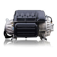
Danfoss TTS700 Service Manual (282 pages)
Twin-Turbine Centrifugal Series Compressors
Brand:
Danfoss
| Category:
Compressor
| Size: 51.71 MB
Table of Contents
Table of Contents
3
Chapter 1: Compressor Introduction
13
Application
15
Purpose
16
Organization
17
Commitment to Quality and the Environment
18
Precautions
18
Refrigerant Type
18
Danger Notification
18
Caution Notification
18
Note
18
R134A/513A
18
Safety Summary
18
Electrical Isolation
19
R1234Ze
19
R515B
19
Handling Static Sensitive Devices
20
ESD Protection/Grounding
21
DC Bus Test Harness Installation and Removal
22
General Verification and Installation of the DC Bus Test Harness
22
DC Bus Test Harness Installation for Closed-Top Soft Start
23
Compressor Fasteners
27
General O-Ring Handling
27
General DC Bus Test Harness Removal
27
DC Bus Test Harness Removal for Closed-Top Soft Starts
27
DC Bus Test Harness Removal for Open-Top Soft Starts
27
Chapter 2: Compressor Fundamentals
29
Figure 2-1 Compressor Fluid Paths
31
Main Fluid Path
31
Motor and Power Electronics Cooling
31
Table 2-1 Compressor Fluid Paths
31
Figure 2-2 Cooling Inlet Adapter
32
Figure 2-3 Split Cooling Path - TTH375/TGH285
33
Figure 2-4 Split Cooling Path - (TTS/TGS (Except TTS300/TGS230 Serial Cooling)
33
Capacity Control
34
Compressor Energy and Signal Flow
34
Figure 2-5 Serial Cooling Path - TTS300/TGS230
34
Figure 2-6 Compressor Energy and Signal Flow Connections
36
Figure 2-7 Compressor Energy and Control Flow Block Diagram - TTS/TGS Compressors
37
Chapter 3: Compressor Removal and Installation
39
Chapter 3: Compressor Removal and Installation
41
Compressor Removal
41
Figure 3-1 Compressor Power Cable Removal
41
Refrigerant Containment
41
Compressor Installation
42
Figure 3-2 Compressor Mounting Fasteners
42
Compressor Replacement Considerations for Motor Cooling Adapter
43
Figure 3-3 Motor Cooling Fitting
43
Exterior Connection Torque Specifications
45
Table 3-1 Exterior Connection Torque Specifications
45
Chapter 4: Compressor Components
47
Component Identification
51
Figure 4-1 Compressor Components Identification (Covers On)
51
Figure 4-9 Service Side Cover
51
Table 4-1 Compressor Components (Covers On)
51
Figure 4-2 Compressor Component Identification - Service Side (Excludes TTH/TGH Compressors)
52
Figure 4-273 BMCC
52
Figure 4-278 PWM
52
Table 4-2 Compressor Components Service Side (Excludes TTH/TGH Compressors)
52
Figure 4-3 Compressor Component Identification - Service Side (TTH/TGH Only)
53
Table 4-3 Compressor Components Service Side (TTH/TGH Only)
53
Figure 4-4 Compressor Component Identification - Capacitor Side (Excludes TTH/TGH)
54
Table 4-4 Compressor Components Capacitor Side (Excludes TTH/TGH)
54
Figure 4-37 Interstage Pipe
55
Figure 4-5 Compressor Component Identification - Capacitor Side (TTH/TGH Only)
55
Table 4-5 Compressor Components Capacitor Side (TTH/TGH Only)
55
Compressor Covers
56
Figure 4-6 Top Covers Removal
56
Mains Input Cover
56
Figure 4-7 Mains Input Cover Torque Sequence
57
Figure 4-8 Top Cover
57
Top Cover
57
Figure 4-10 Service Side Cover
58
Service Side Cover
58
Figure 4-11 Capacitor Cover
59
Figure 4-12 Capacitor Nylon Nuts
59
Capacitor Cover
59
Table 4-6 Compressor Cover Torque Specifications
60
Figure 4-13 Relief Membrane Position
60
Figure 4-14 Recessed Holes
60
Figure 4-15 Capacitor Cover Torque Sequence
60
Compressor Cover Torque Specifications
60
Cooling Adapter
61
Figure 4-16 Cooling Adapter - Excludes TTH375/TGH285
61
Figure 4-17 Cooling Adapter - TTH375/TGH285)
61
Table 4-7 Cooling Adapter Torque Specifications
62
Cooling Adapter Removal and Installation
62
Cooling Adapter Torque Specifications
62
Compressor Interface Module
63
Figure 4-18 Compressor Interface Module Ports & Jumpers
63
Compressor Interface Module Connection Descriptions
63
Compressor Interface Module Verification
65
Table 4-8 CIM Ports and Jumpers
63
Compressor Interface Cable
66
Figure 4-19 Removing the Compressor Interface Module from the DIN Rail
66
Compressor Interface Module Removal & Installation
66
Compressor Controller Cable Harness
67
Figure 4-20 Compressor Interface Cable
67
Compressor Interface Cable Verification
67
Compressor Interface Cable Removal and Installation
67
Figure 4-21 Compressor Controller Cable Harness Variants
68
Compressor Controller Cable Connections
68
Compressor Controller Cable Harness Removal and Installation
68
Figure 4-22 Backplane Connections
69
Figure 4-23 Pressure/Temperature and SCR Temperature Sensor Locations - TTS300/TGS230
69
Figure 4-24 Pressure/Temp and SCR Temp Sensor Locations - TTS/TGS
70
Figure 4-25 Pressure/Temperature Sensors - TTH375/TGH285
70
Figure 4-26 IGV Connector Clamp
70
Figure 4-27 Cable Passage
71
Figure 4-28 Cooling Valve Bodies
72
Figure 4-29 Compressor Cooling Solenoid Coils
72
Compressor Controller Cable Harness Torque Specifications
72
Solenoid and Coil Connections
72
Table 4-10 Solenoid Coil Resistance Ranges
73
Figure 4-30 Solenoid Coil Harness
73
Figure 4-31 Backplane - J16 Connector
73
Solenoid Coil Harness
73
Solenoid Verification
73
Figure 4-32 Compressor Cooling Solenoid Coil Cable Connector
74
Figure 4-33 Backplane - Cool Leds and +24V Test Points
74
Figure 4-34 Solenoid Cooling Path - TTS300/TGS230
74
Figure 4-35 Solenoid Component Removal
75
Solenoid and Coil Removal and Installation
75
Table 4-11 Solenoid Torque Specifications
76
Figure 4-36 Solenoid Actuator Coil Position
76
Solenoids and Coils
72
Table 4-9 Compressor Controller Cable Harness Torque Specifications
72
Figure 4-38 Interstage Pipe Removal
77
Interstage Pipe Removal and Installation
77
Interstage Pipe - TTH/TGH
77
Compressor Housing End Cap
78
Figure 4-39 Compressor Housing End Cap - TTS/TGS
78
Figure 4-40 Compressor Housing End Cap - TTH/TGH
78
Interstage Pipe Torque Specifications
78
Table 4-13 Compressor Housing End Cap Torque Specifications
79
Compressor Housing End Cap Removal and Installation
79
Table 4-12 Interstage Pipe Torque Specifications
78
Figure 4-41 IGV Assembly
80
Figure 4-42 IGV Connections
80
IGV Connections
80
Figure 4-43 IGV Motor Feedthrough
81
Figure 4-44 SMT Icon
81
Figure 4-45 Compressor Configuration Tool
81
IGV Verification
81
Figure 4-46 Control Mode
82
Figure 4-47 Compressor Monitor Tool
82
Figure 4-48 IGV Open Percentage - 100
82
Figure 4-49 IGV Open Percentage - 0
82
Figure 4-50 Backplane Cool Leds
83
Figure 4-51 Backplane +15V Test Point
83
Figure 4-52 IGV Harness Removal
83
IGV Housing Removal and Installation
83
Table 4-15 IGV Feedthrough Wiring Order
84
Figure 4-53 IGV Housing Removal
84
Figure 4-54 IGV Feedthrough Removal
84
Figure 4-55 Set Screw Removal
85
Figure 4-56 IGV Motor Assembly Removal
85
Figure 4-57 Locking Collar Tool
85
Figure 4-58 Locking Collar Removal
86
Figure 4-59 Worm Gear Removal
86
Figure 4-60 Large Worm Gear Bearing Removal
86
Figure 4-61 IGV Throat Removal
87
Figure 4-62 Small Worm Gear Bearing Removal
87
Figure 4-63 Small Worm Gear Bearing Installation
87
Figure 4-64 IGV Position Indicator Magnet
88
Figure 4-65 Large Worm Gear Bearing Installation
88
Figure 4-66 Locking Collar Installation
89
Figure 4-67 IGV Worm Gear Alignment
89
Figure 4-68 Shaft Position
89
Table 4-16 IGV Feedthrough Pin to Wire Reference
90
Figure 4-69 IGV Motor Alignment
90
Figure 4-70 Motor Wire Position
90
Figure 4-71 IGV Motor Wires Connected
91
Figure 4-72 Feedthrough Orientation
91
Figure 4-73 IGV Housing Installation
91
Table 4-17 IGV Torque Specifications
92
Figure 4-74 IGV Position Indicator
92
IGV Torque Specifications
92
Igv
80
Table 4-14 IGV Components
80
Figure 4-75 Mains Plate Bracket
93
Mains Plate Bracket Removal and Installation
93
Figure 4-76 Ground Post Nuts
94
Figure 4-77 Mains Input Nut Installation - TTS300/TGS230 Compressors
94
Figure 4-78 Mains Input Nut Installation - TTS/TGS/TTH/TGH Rev. H and Earlier (Except TTS300/TGS230)
94
Mains Plate Bracket
93
3-Phase Main Voltage Input Terminal Block
95
Figure 4-79 Input Terminal Block - TTS300/TGS230
95
Table 4-18 Mains Plate Torque Specifications
95
Figure 4-80 Input Terminal Block - TTS/TGS/TTH/TGH Rev. H (Except TTS300/TGS230)
96
Figure 4-81 Input Terminal Block - TTS/TGS/TTH/TGH Rev. F and Earlier (Except TTS300/TGS230)
96
3-Phase Main Voltage Input Terminal Block Verification
96
Figure 4-82 Measuring the 3-Phase AC Input Voltage on the AC Input Terminals - TTS300/TGS230
97
Figure 4-83 Measuring 3-Phase AC Input Voltage on AC Input Terminals (TTS/TGS/TTH/TGH (Except TTS300/TGS230)
97
Table 4-19 Expected AC Voltage Range
98
Figure 4-84 Terminal Block Removal - TTS300/TGS230
98
3-Phase Main Voltage Input Terminal Block Removal and Installation
98
Figure 4-85 Input Terminal Block Removal - TTS/TGS/TTH/TGH Rev. F and Earlier (Except TTS300/TGS230)
99
Figure 4-86 Input Terminal Block Removal - TTS/TGS/TTH/TGH Rev. H (Except TTS300/TGS230)
100
Figure 4-87 Input Terminal Block Installation - TTS300/TGS230
100
Figure 4-88 Terminal Block - Input Pressure Screws - TTS300/TGS230
101
Figure 4-89 Input Terminal Block Installation - TTS/TGS/TTH/TGH Rev. F and Earlier (Except TTS300/TGS230)
101
Figure 4-90 Input Terminal Block Installation - TTS/TGS/TTH/TGH Rev. H (Except TTS300/TGS230)
102
Figure 4-91 Input Mains Bus Bar Examples
103
Input Mains Bus Bars (Except TTS300/TGS230)
103
Table 4-20 Terminal Block Torque Specifications
103
Figure 4-92 AC/DC Bus Bus Bar Connectors - TTS/TGS/TTH/TGS Rev. F and Earlier (Except TTS300/TGH230)
104
Figure 4-93 AC/DC Bus Bus Bar Connectors - TTS/TGS/TTH/TGS Rev. H (Except TTS300/TGH230)
104
Figure 4-94 Terminal Block Fuse
105
Verification of Terminal Block Fuse
105
Figure 4-95 Terminal Block Fuse Test
106
Figure 4-96 Terminal Block Fuse Removal
106
Terminal Block Fuse Removal and Installation
106
Table 4-21 AC Bus Bar Torque Specifications
105
Terminal Block Fuse Replacement
105
Figure 4-97 Soft Start Variants
107
Soft Start
107
Table 4-22 Terminal Block Fuse Torque Specifications
107
Figure 4-98 Closed-Top Soft Start Connections
108
Soft Start Connections
108
Table 4-24 Open-Top Soft Start Connection Identification
109
Figure 4-99 Open-Top Soft Start Connections
109
Soft Start Verification
109
Figure 4-100 Soft Start Label Location
110
Figure 4-101 Soft Start Fuse Locations
111
Table 4-25 Soft Start Fuse Details
112
Figure 4-102 Closed-Top Soft Start J9 Connector
112
Soft Start Removal and Installation
112
Soft Start Removal (Closed-Top)
112
Figure 4-103 Ground Location
113
Figure 4-104 Closed-Top Soft Start
113
Figure 4-105 Soft Start Lift
113
Figure 4-106 Closed-Top Soft Start Connector Removal
114
Figure 4-107 Open-Top Soft Start J7 Connector
114
Figure 4-108 Ground Location
114
Soft Start Removal (Open-Top)
114
Figure 4-109 Open-Top Soft Start Connector Removal
115
Figure 4-110 Open-Top Soft Start Removal
115
Figure 4-111 Closed-Top-Soft Start Installation
116
Figure 4-112 Ground Stud Location
116
Soft Start Installation (Closed-Top)
116
Figure 4-113 Open-Top-Soft Start Installation
117
Soft Start Installation (Open-Top)
117
Soft Start Fan Removal and Installation
117
Soft Start Fan Removal
117
Figure 4-114 Soft Start Without Adapter
118
Figure 4-115 Soft Start Fan Orientation
118
Figure 4-116 Soft Start Fan Installation
118
Soft Start Fan Installation
118
Table 4-23 Closed-Top Soft Start Connection Identification
108
Figure 4-117 Soft Start Fan Connector
119
Figure 4-118 SCR DC Bus Bars
119
SCR DC Bus Bar - TTS300/TGS230
119
Table 4-26 Soft Start Torque Specifications
119
Figure 4-119 SCR DC Bus Bar Removal - TTS300/TGS230
120
Figure 4-120 SCR DC Bus Bar to SCR Alignment
120
SCR DC Bus Bar Removal and Installation
120
Figure 4-121 Soft Start SCR Gate Cable (Closed-Top Soft Starts)
121
Figure 4-122 Soft Start SCR Gate Cable (Open-Top Soft Starts)
121
Soft Start SCR Gate Cable Connections
121
Soft Start SCR Gate Cable Removal and Installation
121
Figure 4-123 Soft Start SCR Gate Cable Removal - TTS300/TGS230
122
Figure 4-124 Soft Start SCR Gate Cable Removal at SCR - TTS/TGS/TTH/TGH Models Rev. F and Earlier (Except TTS300/TGS230)
122
Figure 4-125 Soft Start SCR Gate Cable Removal at SCR - TTS/TGS/TTH/TGH Models Rev. H (Except TTS300/TGS230)
122
Figure 4-126 Closed-Top Soft Start J8 Connector Top
123
Figure 4-127 Open-Top Soft Start J2 Connector
123
Soft Start SCR Gate Cable
121
Table 4-27 SCR DC Bus Bar Torque Specifications
121
Figure 4-128 SCR Gate Connector Alignment
124
Soft Start AC/DC Harness
124
Figure 4-129 Soft Start AC/DC Harness Connections - TTS300/TGS230
125
Soft Start AC/DC Harness Connections
125
Figure 4-130 Soft Start AC/DC Harness Connections - TTS/TGS/TTH/TGH (Except TTS300/TGS230)
126
Figure 4-131 AC Input Ring Terminal Removal - TTS300/TGS230
127
Figure 4-132 DC Ring Terminal Removal - TTS300/TGS230
127
Figure 4-133 DC-DC Connectors (Open Frame)
127
Soft Start AC/DC Harness Removal and Installation
127
Figure 4-134 DC-DC Connectors (Potted)
128
Figure 4-135 Closed-Top Soft Start J1 and J7 Removal
128
Figure 4-136 Open-Top Soft Start J1 and J8 Removal
129
Figure 4-137 AC Input Spade and DC Spade Connector Removal - TTS/TGS/TTH/TGH Rev. F and Earlier (Except TTS300/TGS230)
129
Figure 4-138 AC Input Ring and DC Spade Connector Removal - TTS/TGS/TTH/TGH Rev. H (Except TTS300/TGS230)
130
Figure 4-139 Soft Start AC/DC Harness Position - TTS300/TGS230
131
Figure 4-140 AC Input and Spade Connector Installation - TTS/TGS/TTH/TGH Rev. F and Earlier (Except TTS300/TGS230)
132
Figure 4-141 AC Input and Spade Connector Installation - TTS/TGS/TTH/TGH Rev. H (Except TTS300/TGS230)
133
Silicone-Controlled Rectifier
133
Table 4-28 Soft Start AC/DC Harness Torque Specifications
133
Figure 4-142 SCR Styles
134
Figure 4-143 SCR Connections - TTS300/TGS230
134
SCR Connections
134
Figure 4-144 SCR Connections - TTS/TGS/TTH/TGH Rev. F and Earlier (Except TTS300/TGS230)
135
Figure 4-145 SCR Connections - TTS/TGS/TTH/TGH Rev. H (Except TTS300/TGS230)
135
SCR Verification
135
Figure 4-146 SCR Terminals - Two Hole Mount
136
Figure 4-147 SCR Terminals - Four Hole Mount
136
Table 4-29 SCR Diode Values
137
Table 4-30 SCR Gate Resistance Ranges
137
Figure 4-148 SCR Temperature Sensor Assembly
137
Figure 4-149 J17 Connector
137
Figure 4-150 Discharge Pressure/Temperature Sensor Connector Removal - TTS300/TGS230
138
Figure 4-151 SCR Temperature Sensor Connector - TTS300/TGS230
138
Figure 4-152 SCR Temperature Sensor Removal -TTS300/TGS230
139
Figure 4-153 SCR Temperature Sensor Connector - TTS/TGS/TTH/TGH Rev. F and Earlier (Except TTS300/TGS230)
139
Figure 4-154 Discharge Pressure/Temperature Sensor Connector Removal - TTS/TGS/TTH/TGH (Except TTS300/TGS230)
139
Figure 4-155 SCR Temperature Sensor Removal - TTS/TGS/TTH/TGH Rev. F and Earlier (Except TTS300/TGS230)
140
Table 4-31 SCR Temperature Sensor Torque Specifications
141
SCR Removal and Installation
141
Figure 4-156 Fuse Block Assemblies - Two Hole Mount - TTS300/TGS230
142
Figure 4-157 DC Bus Bar Removal - TTS300/TGS230
142
Figure 4-158 SCR Removal - TTS300/TGS230
143
Figure 4-159 SCR Gate Cable and AC/DC Harness Connections - TTS/TGS/TTH/TGH Rev. F and Earlier (Except TTS300/TGS230)
143
Figure 4-160 SCR Gate Cable and AC/DC Harness Connections - TTS/TGS/TTH/TGH Rev. H (Except TTS300/TGS230)
143
Figure 4-161 SCR Bus Fastener Removal - TTS/TGS/TTH/TGH Rev. F and Earlier (Except TTS300/TGS230)
144
Figure 4-162 SCR Bus Fastener Removal - TTS/TGS/TTH/TGH Rev. H (Except TTS300/TGS230)
145
Figure 4-163 SCR Removal - TTS/TGS/TTH/TGH Rev. F and Earlier (Except TTS300/TGS230)
145
Figure 4-164 SCR Removal - TTS/TGS/TTH/TGH Rev. H (Except TTS300/TGS230)
145
Figure 4-165 SCR Heat Sink Paste Application - TTS300/TGS230
146
Figure 4-166 SCR Orientation - TTS300/TGS230
146
Figure 4-167 Bus Bar Installation - TTS300/TGS230
147
Figure 4-168 Bus Bar Locations - TTS300/TGS230
147
Figure 4-169 SCR Thermal Paste Application - TTS/TGS/TTH/TGH (Except TTS300/TGS230)
148
Figure 4-170 SCR Torque Sequence - TTS/TGS/TTH/TGH Rev. F and Earlier (Except TTS300/TGS230)
148
Table 4-32 SCR Torque Specifications
149
Figure 4-172 Inverter Assembly Removal - TTS300/TGS230
150
SCR Cooling Manifold General Removal
150
SCR Cooling Manifold Removal - TTS300/TGS230
150
Figure 4-173 SCR Cooling Manifold Removal - TTS300/TGS230
151
SCR Cooling Manifold Removal - TTS/TGS/TTH/TGH (Except TTS300/TGS230)
151
Figure 4-174 SCR Cooling Manifold Removal
152
Figure 4-175 SCR Cooling Plate O-Ring Installation - TTS300/TGS230
152
SCR Cooling Manifold Installation - TTS300/TGS230
152
Figure 4-176 Inverter Heat Sink Plate O-Ring Installation - TTS/TGS/TTH/TGH (Except TTS300/TGS230)
153
Figure 4-177 SCR Manifold Return Brass Fitting O-Ring Installation - TTS/TGS/TTH/TGH (Except TTS300/TGS230)
153
SCR Cooling Manifold Installation - TTS/TGS/TTH/TGH (Except TTS300/TGS230)
153
Figure 4-178 SCR Cooling Plate Installation - TTS/TGS/TTH/TGH (Except TTS300/TGS230)
154
SCR Cooling Manifold General Installation
154
Table 4-33 SCR Cooling Manifold Torque Specifications
155
Figure 4-171 SCR Cooling Manifold
155
SCR Cooling Manifold Torque Specifications
155
SCR Cooling Manifold
150
DC Capacitor Bus Bar Assembly
156
Figure 4-179 DC Bus Components Identification TTS/TGS/TTH/TGH Rev. F and Earlier (Except TTS300/TGS230)
156
Snubber Capacitors
156
Figure 4-180 DC Bus Components Identification TTS/TGS/TTH/TGH Rev. H (Except TTS300/TGS230)
157
Figure 4-181 Soft Start Cable Harness to DC Bus
157
DC Capacitor DC Bus Bar Connections
157
DC Bus Voltage Verification
158
DC Capacitor Bus Bar Assembly Removal and Installation
158
DC Capacitor Bus Bar Assembly General Removal
158
Figure 4-182 DC Bus Bar and Soft Start Harness Removal - TTS300/TGS230
159
Figure 4-183 Snubber Capacitor Removal - TTS300/TGS230
159
Figure 4-184 Capacitor Nut Removal - TTS300/TGS230
159
Figure 4-185 Capacitor Assembly Removal - TTS300/TGS230
160
Figure 4-186 SCR Bus Bar Removal - TTS/TGS/TTH/TGH Rev. F and Earlier (Except TTS300/TGS230)
160
Figure 4-187 SCR Bus Bar Removal - TTS/TGS/TTH/TGH Rev. H (Except TTS300/TGS230)
161
Figure 4-188 Snubber Capacitor Removal - TTS/TGS/TTH/TGH (Except TTS300/TGS230)
161
Figure 4-189 Capacitor Nut Removal - TTS/TGS/TTH/TGH (Except TTS300/TGS230)
161
Figure 4-190 Capacitor Assembly Removal - TTS/TGS/TTH/TGH Rev. F and Earlier (Except TTS300/TGS230)
162
Figure 4-191 Capacitor Assembly Removal - TTS/TGS/TTH/TGH Rev. H (Except TTS300/TGS230)
162
DC Capacitor Bus Bar Assembly General Installation Steps
163
Table 4-34 DC Capacitor Bus Bar Assembly Torque Specifications
164
DC Capacitor Bus Bar Assembly Torque Specifications
164
Figure 4-192 Inverter Connections
165
Inverter Connections
165
Inverter Verification
165
Figure 4-193 Inverter Diode Measurements (Skiip 613 Shown)
166
Inverter Cable Harness
166
Inverter Cable Harness Removal and Installation
166
Figure 4-194 Inverter Cable Harness
167
Figure 4-195 Harness Removal from Inverter
167
Figure 4-196 Harness Removal from Backplane
167
Inverter Cable Harness Installation
167
Table 4-35 Inverter Cable Harness Torque Specifications
168
Figure 4-197 Inverter Connector Alignment
168
Inverter Removal and Installation
168
Figure 4-198 Fuse Block Assemblies - TTS300/TGS230
169
Figure 4-199 Terminal Block Removal - TTS300/TGS230
169
Figure 4-200 Soft Start Harness Removal
170
Figure 4-201 DC Bus Bar Removal
170
Figure 4-202 DC Bus Bar Mylar Removal - TTS300/TGS230
170
Figure 4-203 Inverter Copper Tube Removal
171
Figure 4-204 Inverter Cable Harness Removal - TTS300/TGS230
172
Figure 4-205 Open-Frame DC-DC
172
Figure 4-206 Potted DC-DC
172
Figure 4-207 DC-DC Removal (Potted DC-DC Shown)
173
Figure 4-208 Motor Winding Sensor Connector Removal
173
Figure 4-209 Retainer Clip Rotation
173
Figure 4-210 Compressor Cable Harness Removal - TTS300/TGS230
174
Figure 4-211 Inverter Assembly Removal - TTS300/TGS230
174
Figure 4-212 SCR Cooling Manifold Removal - TTS300/TGS230
175
Figure 4-213 SCR Connections - TTS/TGS/TTH/TGH Rev. F and Earlier (Except TTS300/TGS230)
175
Figure 4-214 SCR Connections - TTS/TGS/TTH/TGH Rev. H (Except TTS300/TGS230)
176
Figure 4-215 Terminal Block and AC Mains Input Bus Bar Removal - TTS/TGS/TTH/TGH Rev. F and Earlier (Except TTS300/TGS230)
176
Figure 4-216 Input Terminal Block Removal - TTS/TGS/TTH/TGH Rev. H (Except TTS300/TGS230)
177
Figure 4-217 Inverter Copper Tube Removal - TTS/TGS/TTH/TGH (Except TTS300/TGS230)
177
Figure 4-218 Retainer Clip Rotation
178
Figure 4-219 Compressor Cable Harness Removal - TTS/TGS/TTH/TGH (Except TTS300/TGS230)
178
Figure 4-220 Compressor Cable Harness Removal - TTH/TGH Only
178
Figure 4-221 SCR Manifold Removal - TTS/TGS/TTH/TGH (Except TTS300/TGS230)
179
Figure 4-222 Inverter Harness Removal - TTS/TGS/TTH/TGH (Except TTS300/TGS230)
179
Figure 4-223 DC-DC Removal - TTS/TGS/TTH/TGH Rev. F and Earlier (Except TTS300/TGS230)
180
Figure 4-224 Motor Winding Sensor Removal
180
Figure 4-225 Inverter Removal - TTS/TGS/TTH/TGH (Except TTS300/TGS230)
180
Figure 4-226 Inverter O-Ring Removal - TTS/TGS/TTH/TGH (Except TTS300/TGS230)
181
Figure 4-227 SCR Manifold Return Brass Fitting Removal - TTS/TGS/TTH/TGH (Except TTS300/TGS230)
181
Figure 4-228 SCR Cooling Plate O-Ring Installation - TTS300/TGS230
182
Figure 4-229 Inverter Fastener Locations - TTS300/TGS230
182
Figure 4-230 DC Bus Installation - TTS300/TGS230
183
Figure 4-231 Terminal Block Installation - TTS300/TGS230
184
Figure 4-232 Inverter Fastener Locations - TTS/TGS/TGH (Except TTS300/TGS230)
184
Figure 4-233 Inverter Heat Sink Plate O-Ring Installation - TTS/TGS (Except TTS300/TGS230)
185
Figure 4-234 SCR Manifold Return Brass Fitting O-Ring Installation - TTS/TGS (Except TTS300/TGS230)
185
Figure 4-235 SCR Cooling Plate Installation - TTS/TGS/TTH/TGH (Except TTS300/TGS230)
185
Figure 4-236 DC Bus Capacitor Assembly Installation - TTS/TGS/TTH/TGH (Except TTS300/TGS230)
186
Figure 4-237 Driver Board Fasteners
187
Inverter Card Replacement
187
Figure 4-238 Driver Board Removal
188
Figure 4-239 Seated Spring Pins
188
Figure 4-240 Spring Locations
188
Table 4-36 Spring Identification Table
189
Figure 4-241 Spring Pin Identification
189
Figure 4-242 Driver Board Placement
189
Table 4-37 Inverter Torque Specifications
190
Figure 4-243 Initial Tightening Pass Sequence
190
Inverter Torque Specifications
190
Inverter
165
Motor Components
191
Function
191
Motor Protection
191
Figure 4-244 Connection to Stator
192
Motor Connections
192
Motor Verification
192
Figure 4-245 Stator Thermistor R/T Curve 1
193
Motor Assembly Removal and Installation
193
Figure 4-246 Motor Bus Bar Removal - PPS Feedthroughs
194
Figure 4-247 Motor Bus Bar Removal - Stainless-Steel Feedthroughs
194
Figure 4-248 Copper Tube Removal
195
Figure 4-249 Motor Cover Plate Removal
196
Figure 4-250 Thermistor Connector Removal
196
Figure 4-251 Cover Plate Torque Sequence
197
Figure 4-252 High-Power Feedthrough (PPS)
198
Figure 4-253 High-Power Feedthrough Removal (Stainless Steel)
198
Table 4-38 Motor Assembly Torque Specifications
200
Figure 4-254 Connection to Stator
200
High Voltage DC-DC Converter
201
DC-DC Converter Function
201
DC-DC Converter Verification
201
Figure 4-255 J3 - 24VDC Output Connector
202
Figure 4-256 DC-DC Harness
202
DC-DC Supply Cable Harness
202
Figure 4-257 DC-DC Harness Routing
203
DC-DC Harness Removal and Installation
203
Figure 4-258 Potted DC-DC
204
Figure 4-259 Open Frame DC-DC
204
Figure 4-260 DC-DC Converter Removal
205
Figure 4-261 DC-DC Rear Fastener Install
205
Table 4-39 DC-DC Torque Specifications
206
Figure 4-262 Potted DC-DC - Top View
206
Figure 4-263 Open Frame DC-DC - Top View
206
Backplane
207
Figure 4-264 Backplane
207
Backplane Function
207
Table 4-40 Backplane Connections
208
Figure 4-265 Backplane Connections
208
Backplane Connections and Test Points
208
Table 4-41 Backplane Test Points
209
Figure 4-266 Backplane Test Points
209
Figure 4-267 Backplane LED Locations - Left Side
209
Table 4-42 Backplane LED Locations
210
Figure 4-268 Backplane LED Locations - Right Side
210
Table 4-43 Backplane Test Point Values
211
Figure 4-269 Removing the Backplane
211
Backplane Removal and Installation
211
Figure 4-270 Serial Driver
212
Serial Driver Function
212
Serial Driver Connections
213
Serial Driver Verification
213
Serial Driver Removal and Installation
213
Serial Driver
212
Table 4-44 Backplane Torque Specifications
212
Bmcc
214
Figure 4-271 Serial Driver Removal
214
Figure 4-272 Insertion Guides
214
BMCC Connections
215
BMCC Verification
215
BMCC Battery and Verification
215
Figure 4-274 BMCC Case Separation
216
Figure 4-275 BMCC Battery Measurement
217
Figure 4-276 BMCC Removal
217
BMCC Removal and Installation
217
Bearing Pulse Width Modulator Amplifier
218
Figure 4-277 BMCC Insertion Guides
218
PWM Function
218
Figure 4-279 Bearing Control Signal Flow
219
Figure 4-280 Bearing Power Feed Throughs and PWM Connection Port
219
PWM Connections
219
PWM Verification
220
Figure 4-281 Connecting Leads to PWM Connector and HV- and HV+ Test Points
221
PWM Removal and Installation
221
Table 4-45 PWM Torque Specifications
222
Figure 4-282 Removing the PWM Amplifier
222
Figure 4-283 PWM Amplifier Installation
222
Figure 4-284 Bearing Connections
223
Magnetic Bearings Function
223
Magnetic Bearings Connections
223
Bearing Verification
223
Table 4-46 Magnetic Bearing Coil Resistance Values
224
Figure 4-285 Front and Rear Bearing Feed through Connectors
224
Table 4-47 Bearing Amperage Nominal Ranges
225
Figure 4-286 Compressor Monitor Tool
225
Figure 4-287 Bearing Power Feedthrough Assembly
226
Bearing Power Feedthrough Removal and Installation
226
Figure 4-288 Bearing Power Feedthrough Alignment Pin
227
Figure 4-289 Bearing Power Feedthrough Torque Sequence
227
Magnetic Bearings
223
Bearing Sensors
228
Figure 4-290 Bearing Sensor Feedthroughs
228
Bearing Sensor Function
228
Bearing Sensor Connection
228
Table 4-49 Bearing Sensor Coil Resistance
229
Figure 4-291 Bearing Sensor Pin Locations
229
Bearing Sensor Verification
229
Bearing Sensor Cable Removal and Installation
229
Bearing Sensor Removal and Installation
229
Figure 4-292 Bearing Sensor Feed through Removal
230
Figure 4-293 Bearing Sensor 9-Pin Feedthrough Connector Torque Sequence
230
Table 4-48 Magnetic Bearing Torque Specifications
228
Cavity Temperature Sensor
231
Figure 4-294 BMCC Insertion Guides
231
Figure 4-295 Cavity Sensor
231
Cavity Temperature Sensor Function
231
Figure 4-296 Cavity Temperature Sensor Terminal
232
Cavity Temperature Sensor Connections
232
Cavity Temperature Sensor Verification
232
Cavity Temperature Sensor Removal and Installation
232
Table 4-51 Cavity Sensor Torque Specifications
233
Figure 4-298 Cavity Temperature Sensor Removal
233
Table 4-50 Bearing Sensor Torque Specifications
231
Figure 4-300 Pressure/Temperature Sensor Connections (All TTS/TGS Compressors)
234
Figure 4-301 Pressure/Temperature Sensor Locations (TTH/TGH)
234
Pressure/Temperature Sensor Function
234
Pressure/Temperature Sensor Connections
234
Pressure/Temperature Sensor Verification
234
Figure 4-297 Temperature Vs. Resistance
235
Figure 4-299 Pressure/Temperature Sensor
235
Figure 4-302 Temperature Vs. Resistance
235
Figure 4-303 Pressure/Temperature Cable Terminals
235
Figure 4-304 Pressure/Temperature Sensor Pin Locations
235
Figure 4-305 Suction Pressure/Temperature Sensor Removal
236
Figure 4-306 Discharge Pressure/Temperature Sensor
236
Pressure/Temperature Sensor Removal and Installation
236
Table 4-52 Pressure/Temperature Sensor Torque Specifications
237
Figure 4-307 Interstage Pressure/Temperature Sensor Removal
237
Pressure/Temperature Sensor
234
Advertisement
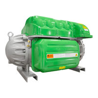
Danfoss TTS700 Service Manual (294 pages)
Twin-Turbine Centrifugal Series Compressors
Brand:
Danfoss
| Category:
Air Compressor
| Size: 43.2 MB
Table of Contents
Table of Contents
3
Chapter 1.0 Introduction
17
Application
17
Purpose
19
Organization
19
Commitment to Quality and the Environment
20
Safety Summary
20
Danger Notification
20
Caution Notification
21
Note
21
Precautions
21
Refrigerant Type
21
Electrical Isolation
22
Handling Static Sensitive Devices
24
ESD Protection/Grounding
24
DC Bus Test Harness Installation and Removal
25
General Verification and Installation of the DC Bus Test Harness
26
DC Bus Test Harness Installation for Closed-Top Soft Start
27
DC Bus Test Harness Installation for Open-Top Soft Starts
30
General DC Bus Test Harness Removal
31
DC Bus Test Harness Removal for Closed-Top Soft Starts
31
DC Bus Test Harness Removal for Open-Top Soft Starts
31
Compressor Fasteners
32
General O-Ring Handling
32
Chapter 2.0 Compressor Fundamentals
33
Main Fluid Path
33
Motor and Power Electronics Cooling
33
Capacity Control
37
Compressor Energy and Signal Flow
38
Chapter 3.0 Compressor Removal and Installation
41
Refrigerant Containment
41
Compressor Removal
41
Compressor Installation
42
Compressor Replacement Considerations for Motor Cooling Adapter
43
Exterior Connection Torque Specifications
45
Chapter 4.0 Component Identification
47
Compressor Covers
52
Mains Input Cover
52
Mains Input Cover Removal and Installation
52
Top Cover
53
Top Cover Removal and Installation
53
Service Side Cover
54
Service Side Cover Removal and Installation
54
Capacitor Cover
55
Capacitor Cover Removal and Installation
55
Compressor Cover Torque Specifications
57
Cooling Adapter
58
Cooling Adapter Removal and Installation
59
Cooling Adapter Torque Specifications
59
Compressor Interface Module
60
Compressor Interface Module Connection Descriptions
60
Compressor Interface Module Verification
62
Determining if the Compressor Interface Module Is Draining Energy
62
Compressor Interface Module Communication Verification
62
Interlock Verification
63
Compressor Interface Module Removal & Installation
63
Compressor Interface Module Removal
63
Compressor I/O Board Installation
64
Compressor Interface Cable
65
Compressor Interface Cable Verification
65
Compressor Interface Cable Removal and Installation
65
Compressor Interface Cable Removal
65
Compressor Interface Cable Installation
65
Compressor Controller Cable Harness
67
Compressor Controller Cable Connections
67
Compressor Controller Cable Harness Removal and Installation
68
Compressor Controller Cable Harness Torque Specifications
71
Solenoids and Coils
72
Solenoid and Coil Connections
72
Solenoid Coil Harness
73
Solenoid Coil Harness Removal and Installation
73
Solenoid Verification
73
Resistance Measurement of Cooling Solenoid Coils
73
Output Voltage to Solenoid Coils
74
Cooling Path Blockage Inspection
74
Solenoid and Coil Removal and Installation
75
Solenoid and Coil Removal
75
Solenoid and Actuator Installation
76
Solenoid Torque Specifications
77
Interstage Pipe - TTH/TGH
78
Interstage Pipe Removal and Installation
78
Interstage Pipe Removal
78
Interstage Pipe Installation
78
Interstage Pipe Torque Specifications
79
Compressor Housing End Cap
80
Compressor Housing End Cap Removal and Installation
80
Compressor Housing End Cap Removal
80
Compressor Housing End Cap Installation
81
Compressor Housing End Cap Torque Specifications
81
Igv
82
IGV Connections
82
IGV Verification
83
IGV Stepper Motor Verification
83
IGV Operation Verification
83
IGV Housing Removal and Installation
85
IGV Housing Assembly Removal
85
IGV Assembly Removal
87
IGV Assembly Installation
90
IGV Torque Specifications
95
Mains Plate Bracket
96
Mains Plate Bracket Removal and Installation
96
Mains Plate Bracket Removal
96
Mains Plate Bracket Installation
96
Mains Plate Torque Specifications
98
3-Phase Main Voltage Input Terminal Block
99
3-Phase Main Voltage Input Terminal Block Verification
100
3-Phase AC Input Verification
100
Connecting the AC Input Cable
100
Verifying the 3-Phase AC Input
101
3-Phase Main Voltage Input Terminal Block Removal and Installation
102
General 3-Phase Main Voltage Input Terminal Block Removal
102
Specific 3-Phase Main Voltage Input Terminal Block Removal - TTS300/TGS230
102
3-Phase Main Voltage Input Terminal Block Removal - TTS/TGS/TTH/TGH (Except TTS300/TGS230)
103
3-Phase Main Voltage Input Terminal Block Installation - TTS300/TGS230
104
3-Phase Main Input Terminal Block Installation - TTH/TGH/TTH/TGH (Except TTS300/TGS230)
105
General 3-Phase Main Voltage Input Terminal Block Installation
106
Terminal Block Torque Specifications
106
Input Mains Bus Bars
108
Input Mains Bus Bar Removal
108
General Mains Bus Bar Removal
108
Input Mains Bus Bar Installation
109
General Mains Bus Bar Installation
110
AC Bus Bar Torque Specifications
110
Terminal Block Fuse Replacement
111
Verification of Terminal Block Fuse
111
Terminal Block Fuse Removal and Installation
111
Terminal Block Fuse Removal
111
Terminal Block Fuse Installation
112
Soft Start
113
Soft Start Connections
114
Soft Start Verification
115
Verifying Soft Start Voltages
115
Verifying Soft Start Fuses
116
Soft Start Removal and Installation
117
Soft Start Removal (Closed-Top)
117
Soft Start Removal (Open-Top)
119
Soft Start Installation (Closed-Top)
121
Soft Start Installation (Open-Top)
122
Soft Start Fan Removal and Installation
123
Soft Start Fan Removal
123
Soft Start Fan Installation
124
Soft Start Torque Specifications
125
SCR DC Bus Bar - TTS300/TGS230
126
SCR DC Bus Bar Removal and Installation
126
SCR DC Bus Bar Removal - TTS300/TGS230
126
SCR DC Bus Bar Installation - TTS300/TGS230
126
SCR DC Bus Bar Torque Specifications
127
Soft Start SCR Gate Cable
128
Soft Start SCR Gate Cable Connections
128
Soft Start SCR Gate Cable Removal and Installation
128
Soft Start SCR Gate Cable Removal
128
Soft Start SCR Gate Cable Installation
130
Soft Start AC/DC Harness
132
Soft Start AC/DC Harness Connections
132
Soft Start AC/DC Harness Removal and Installation
133
Soft Start AC/DC Harness Removal - TTS300/TGS230
133
Soft Start AC/DC Harness Removal - TTS/TGS/TTH/TGH (Except TTS300/TGS230)
136
Soft Start AC/DC Harness Installation - TTS300/TGS230
137
Soft Start AC/DC Harness Installation - TTS/TGS/TTH/TGH (Except TTS300/TGS230)
138
Soft Start AC/DC Harness Torque Specifications
140
Silicone-Controlled Rectifier
141
SCR Connections
141
SCR Verification
142
Diodes Verification - Two-Hole Mount
142
Diodes Verification - Four-Hole Mount
143
Gates Verification
144
SCR Temperature Sensor
144
SCR Temperature Sensor Verification
144
SCR Temperature Sensor General Removal
145
SCR Temperature Sensor Removal - TTS300/TGS230
145
SCR Temperature Sensor Removal - TTS/TGS/TTH/TGH Rev. F and Earlier (Except TTS300/TGS230)
146
SCR Temperature Sensor Installation - TTS300/TGS230
148
SCR Temperature Sensor Installation - TTS/TGS/TTH/TGH Rev. F and Earlier
148
Tts300/Tgs230)
148
SCR Temperature Sensor General Installation
148
SCR Temperature Sensor Torque Specifications
148
SCR Removal and Installation
149
SCR General Removal
149
SCR Removal - TTS300/TGS230
149
SCR Removal - TTS/TGS/TTH/TGH (Except TTS300/TGS230)
150
SCR Installation - TTS300/TGS230
153
SCR Installation - TTS/TGS/TTH/TGH (Except TTS300/TGS230)
155
SCR General Installation
156
SCR Torque Specifications
156
SCR Cooling Manifold
157
SCR Cooling Manifold General Removal Steps
157
SCR Cooling Manifold Specific Removal Steps - TTS300/TGS230
157
SCR Cooling Manifold Specific Removal Steps - TTS/TGS/TTH/TGH (Except TTS300/TGS230)
159
SCR Cooling Manifold Specific Installation Steps - TTS300/TGS230
160
SCR Cooling Manifold Specific Installation Steps - TTS/TGS/TTH/TGH (Except TTS300/TGS230)
160
SCR Cooling Manifold General Installation Steps
162
SCR Cooling Manifold Torque Specifications
162
Snubber Capacitors
164
DC Capacitor Bus Bar Assembly
165
DC Capacitor DC Bus Bar Connections
166
DC Bus Voltage Verification
167
Bleed Resistor Verification
167
Snubber Capacitor Verification
167
DC Capacitor Bus Bar Assembly Removal and Installation
168
DC Capacitor Bus Bar Assembly General Removal
168
DC Capacitor Bus Bar Assembly Removal - TTS300/TGS230
168
DC Capacitor Bus Bar Assembly Removal - TTS/TGS/TTH/TGH (Except TTS300/TGS230)
170
DC Capacitor Bus Bar Assembly Installation - TTS300/TGS230
174
DC Capacitor Bus Bar Assembly Installation - TTS/TGS/TTH/TGH (Except TTS300/TGS230)
174
DC Capacitor Bus Bar Assembly General Installation Steps
174
DC Capacitor Bus Bar Assembly Torque Specifications
174
Inverter
176
Inverter Connections
176
Inverter Verification
176
Inverter Cable Harness
177
Inverter Cable Harness Removal and Installation
177
Inverter Cable Harness Removal
177
Inverter Cable Harness Installation
178
Inverter Cable Harness Torque Specifications
179
Inverter Removal and Installation
179
Compressor Specific Inverter Removal Steps - TTS300/TGS230
179
Compressor Specific Inverter Removal Steps - TTS/TGS/TTH/TGH (Except TTS300/TGS230)
182
Compressor Specific Inverter Installation Steps - TTS300/TGS230
185
Compressor Specific Inverter Installation Steps - TTS/TGS/TTH/TGH (Except TTS300/TGS230)
187
Inverter Card Replacement
188
Inverter Card Removal
188
Inverter Control Card Installation
189
Inverter Torque Specifications
192
Motor Components
194
Function
194
Stator
194
Rotor
194
Motor Protection
194
Motor Connections
194
Motor Verification
195
Stator Insulation Verification
195
Stator Resistance Verification
195
Stator Thermistor Resistance Verification
195
Motor Components Removal and Installation
196
Motor Bus Bar Removal
196
Motor Bus Bar Installation
197
Copper Tube Removal
198
Copper Tube Installation
198
Motor Cover Plate Removal
198
Motor Cover Plate Installation
199
High Power Feedthrough Removal
200
High-Power Feedthrough Installation
202
Motor Assembly Torque Specifications
203
High Voltage DC-DC Converter
204
DC-DC Converter Function
204
DC-DC Converter Verification
204
Input Voltage Verification
204
Output Voltage Verification
204
Input Resistance Measurement
205
Output Resistance Measurement
205
DC-DC Removal and Installation
206
DC-DC Torque Specifications
208
DC-DC Supply Cable Harness
209
DC-DC Harness Removal and Installation
209
DC-DC Harness Removal
209
DC-DC Harness Installation
210
Backplane
211
Backplane Function
211
Backplane Connections and Test Points
211
LED Locations
213
Backplane Verification
214
Backplane Removal and Installation
215
Backplane Removal
215
Backplane Installation
216
Backplane Torque Specifications
216
Serial Driver
217
Serial Driver Function
217
Serial Driver Connections
217
Serial Driver Verification
217
Serial Driver Input Voltage
217
Serial Driver Output Voltage Verification
218
Serial Driver Removal and Installation
218
Serial Driver Removal
218
Serial Driver Installation
218
Bmcc
220
BMCC Connections
220
BMCC Verification
220
BMCC Power Verification
220
BMCC Communication Verification
220
BMCC Battery and Verification
221
BMCC Battery Safety
221
BMCC Battery Verification
221
BMCC Removal and Installation
222
BMCC Removal
222
BMCC Installation
223
Bearing Pulse Width Modulator Amplifier
225
PWM Function
225
PWM Connections
226
PWM Verification
226
Verify if the Bearing PWM Amplifier Is Draining Energy
227
Verify Functionality of the Five Output Channels
227
Verify Functionality of the Five Diode Sets
227
PWM Removal and Installation
228
PWM Amplifier Removal
228
PWM Amplifier Installation
229
PWM Torque Specifications
229
Magnetic Bearings
230
Magnetic Bearings Function
230
Magnetic Bearings Connections
230
Bearing Verification
230
Bearing Coil Verification
230
Bearing Current Verification
232
Bearing Power Feedthrough Removal and Installation
233
Bearing Power Feedthrough Removal
233
Bearing Power Feedthrough Installation
234
Magnetic Bearing Torque Specifications
235
Bearing Sensors
236
Bearing Sensor Function
236
Bearing Sensor Connection
236
Bearing Sensor Verification
236
Bearing Sensor Resistance Verification
236
Bearing Sensor Cable Verification
237
Bearing Sensor Cable Removal and Installation
238
Bearing Sensor Feedthrough Removal and Installation
239
Bearing Sensor Feedthrough Removal
239
Bearing Sensor Feedthrough Installation
240
Bearing Sensor Torque Specifications
241
Cavity Temperature Sensor
242
Cavity Temperature Sensor Function
242
Cavity Temperature Sensor Connections
242
Cavity Temperature Sensor Verification
242
Cavity Temperature Sensor Removal and Installation
243
Cavity Temperature Sensor Removal
243
Cavity Temperature Sensor Installation
243
Cavity Sensor Torque Specifications
244
Pressure/Temperature Sensor
245
Pressure/Temperature Sensor Function
245
Pressure/Temperature Sensor Connections
245
Pressure/Temperature Sensor Verification
246
Pressure/Temperature Sensor Removal and Installation
247
Suction Pressure/Temperature Sensor Removal
247
Suction Pressure/Temperature Sensor Installation
248
Discharge Pressure/Temperature Sensor Removal
248
Discharge Pressure/Temperature Sensor Installation
248
Interstage Pressure/Temperature Sensor Removal (TTH/TGH Compressors Only)
249
Interstage Pressure/Temperature Sensor Installation (TTH/TGH Compressors Only)
249
Pressure/Temperature Sensor Torque Specifications
249
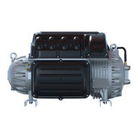
Danfoss TTS700 Applications And Installation Manual (114 pages)
Twin-Turbine Centrifugal Compressors
Brand:
Danfoss
| Category:
Air Compressor
| Size: 20.3 MB
Table of Contents
Table of Contents
3
Chapter 1.0 Introduction
11
Scope
11
Organization of this Manual
11
Document Symbols
11
Table 1-1 Application Manual Applicability
11
Table 1-2 Acronyms and Terms
13
Chapter 2.0 Overview of the TTS/TGS/TTH/TGH Compressor
17
TTS/TGS/TTH/TGH Compressor Nomenclature
17
Figure 2-1 Old Type Code to New Type Code Rev. D
17
Refrigerant Type
18
Table 2-1 Refrigerant Used with Turbocor Compressors
18
Figure 2-2 Compressor Nomenclature
18
Environment
19
Mains Plate Sealing
19
Configurations of the TTS/TGS/TTH/TGH Compressor Models
20
Compressor Module
20
Figure 2-3 Major Components
20
Chapter 3.0 Functional Description
21
Main Fluid Path
21
Figure 3-1 Compressor Fluid Path TGS230/TTS300
21
Motor Cooling
22
Figure 3-2 Compressor Fluid Path (TGS310, TTS350, TGS390, TGS490, TTS400, TGS520, and TTS700)
22
Figure 3-3 Compressor Cooling Circuit (TGS230 / TTS300)
23
Figure 3-4 Compressor Cooling Circuit (TTS300 Split-Cooling, TGS310, TTS350, TGS390, TGS490, TTS400, TT700, and TGS520)
23
Inlet Guide Vanes
24
Compressor Control Overview
24
Figure 3-5 Compressor Cooling Circuit (TGH285 / TTH375)
24
Figure 3-6 Compressor Control System Functional Block Diagram
25
Magnetic Bearing System
27
Table 3-1 Backplane Leds
27
Figure 3-7 Magnetic Bearing Configuration
27
Figure 3-8 Magnetic Bearing Control System
28
Chapter 4.0 Control Interface Wiring
29
Figure 4-1 Typical Control Wiring
29
Figure 4-2 Modbus Grounding Diagram
30
Table 4-1 Control Wiring Details
31
Table 4-2 Jumper Details
31
Control Wiring Connection Guidelines
32
Figure 4-3 I/O Wiring Specifications
32
Interface Cable
32
Compressor I/O Board Mounting Details
33
Figure 4-4 Compressor I/O Board
33
Figure 4-5 Compressor I/O Board Installation
33
Chapter 5.0 General Specifications
35
Construction
35
Maximum Pressure
35
Table 5-1 Discharge Pressure Alarm and Trip Settings
35
Maximum Discharge Temperature
36
Table 5-2 Discharge Temperature Trip Settings
36
Table 5-3 Maximum Pressure Ratio Limits
36
Table 5-4 Maximum Allowable Pressure [PS]
36
Suction Pressure Limits
37
Standards Compliance
37
Table 5-5 Suction Pressure Alarm and Trip Settings
37
Chapter 6.0 Electrical Specifications
39
Supply Voltage and Frequency
39
Compressor Current Limit and Operating Range Settings
39
Table 6-1 Acceptable AC Voltage Range
39
Table 6-2 Acceptable Frequency Range
39
Disconnects
40
Table 6-3 FLA and LRA Value Range
40
Motor Insulation Class
41
AC Input Line/Power Electronic Component Protection
41
Power Line Contactor
41
CE Compliance and EMI/EMC Filtering
41
Surge Protection
42
Line Reactor
42
Harmonic Current Filtering (IEEE 519)
42
Grounding (Earth) Connection Guidelines
42
Equipment Panel
43
Mains Input Cable Specification
43
Figure 6-1 Typical Ground Connections
43
Idle Power Consumption
44
Table 6-4 Main Cable Connector Plate Hole Sizes
44
Chapter 7.0 Compressor Performance
45
Performance Ratings
45
Tolerance of Performance Ratings
45
Chapter 8.0 Operating Envelopes
47
Figure 8-1 Operating Envelope, TTS300 and TGS230
47
Figure 8-2 Operating Envelope, TTS300 and TGS230 (Medium Temperature Compressor)
48
Figure 8-3 Operating Envelope, TTS350, TGS310
49
And TGS490
49
Figure 8-4 Operating Envelope, TTS400 and TGS390
50
Figure 8-5 Operating Envelope, TTS700 and TGS520
51
Figure 8-6 Operating Envelope, TTH375/TGH285
52
Chapter 9.0 Minimum Unloading Capacity
53
Chapter 10.0 Control Logic Guidelines for Multiple Compressors
55
Chapter 11.0 Product Certification
57
Chapter 12.0 Guide Specifications
59
General
59
Refrigerant
59
Compressor Bearings
59
Capacity Control
59
Compressor Motor
59
Compressor Electronics
60
Chapter 13.0 System Design Guidelines
61
General Requirements
61
Table 13-1 Recommended Minimum Copper Tube Size
61
Economizer Option
62
Motor/Electronics Cooling Requirements
62
Figure 13-1 Discharge Cone to Illustrate the Piping Requirements
62
Electrical Requirements
63
Application-Specific Requirements
63
Table 13-2 Low Lift Pump Sizing
64
Figure 13-2 Centrifugal Performance Dynamics
64
Chapter 14.0 Sample Refrigeration Circuits
65
Figure 14-1 Typical Refrigeration Piping Schematic
65
Figure 14-2 Typical Refrigeration Piping Schematic with Staging and Load Balancing Valve
66
Figure 14-3 Typical Refrigeration Piping Schematic with Flash Tank Economizer
67
Figure 14-4 Typical Refrigeration Piping Schematic with Closed Type Economizer
68
Figure 14-5 Typical Refrigeration Piping Schematic Using Motor-Cooling Pressure Regulating Valve (TTS300/TGS230 Medium Temperature Compressors Only)
69
Figure 14-6 Typical Refrigeration Piping Schematic Using Motor-Cooling Pressure Regulating Valve (TTH/TGH Medium Temperature Compressors Only)
70
Figure 14-7 Typical Refrigeration Piping Schematic with Multiple DX Evaporators
71
Figure 14-8 Multiple Compressors Single Circuit Piping Schematic
72
Figure 14-9 TTH/TGH Piping Schematic with Required Economizer (Closed Type) and Vapor Line Solenoid
73
Figure 14-10 TTH/TGH Piping Schematic with Required Economizer (Flash Tank) and Vapor Line Solenoid
74
Chapter 15.0 Sound and Power Specifications
75
TTS300 and TTS400 Sound Power Measurements
75
Table 15-1 Sound Power Measurements for TTS300
75
Table 15-2 Sound Pressure Calculation for TTS300
75
Table 15-3 Sound Power at Third Octave Band, TTS300 Compressor
76
Table 15-4 Sound Power Measurements, TTS400 Compressor
76
Table 15-5 Sound Pressure Calculation, TTS400 Compressor
76
Table 15-6 Sound Power at Third Octave Band of TTS400 Compressor
77
Advertisement
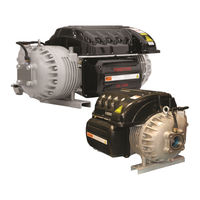
Danfoss TTS700 Applications And Installation Manual (136 pages)
Twin-Turbine
Brand:
Danfoss
| Category:
Air Compressor
| Size: 48.94 MB
Table of Contents
Table of Contents
3
Chapter 1.0 Introduction
11
Scope
11
Document Symbols
11
Chapter 2.0 Compressor Overview
19
TTS/TGS/TTH/TGH Compressor Nomenclature
19
Refrigerant Type
21
Environment
21
Configurations of the TTS/TGS/TTH/TGH Compressor Models
22
Compressor Module
23
Chapter 3.0 Functional Description
25
Main Fluid Path
25
Motor Cooling
26
Inlet Guide Vanes
29
Compressor Control Overview
30
Motor Drive System
30
Soft Start
31
Bearing Motor Compressor Controller
31
Compressor Control
31
Capacity Control
31
Expansion Valve Control
31
Motor/Bearing Control
31
Monitoring Functions
32
Abnormal Conditions
32
Bearing PWM Amplifier
32
Serial Driver
32
Backplane
32
High-Voltage DC-DC Converter
33
Magnetic Bearing System
33
Overview
33
Bearing Control System
33
Chapter 4.0 Control Interface Wiring
35
Control Wiring Connection Guidelines
37
Interface Cable
38
Compressor I/O Board Mounting Details
39
Compressor I/O Board Mounting Instructions
39
Chapter 5.0 General Specifications
41
Construction
41
Maximum Pressure
41
Maximum Discharge Temperature
41
Suction Pressure Limits
42
Standards Compliance
43
Chapter 6.0 Electrical Specifications
45
Supply Voltage and Frequency
45
Voltage Sag Immunity
45
Compressor Current Limit and Operating Range Settings
45
Disconnects
47
Motor Insulation Class
47
AC Input Line/Power Electronic Component Protection
47
Power Line Contactor
48
CE Compliance and EMI/EMC Filtering
48
Surge Protection
49
Line Reactor
49
Harmonic Current Filtering (IEEE 519)
49
Grounding (Earth) Connection Guidelines
49
Equipment Panel
50
Mains Input Cable Specification
51
Idle Power Consumption
51
Chapter 7.0 Compressor Performance
53
Performance Ratings
53
Tolerance of Performance Ratings
53
Chapter 8.0 Operating Envelopes
55
Chapter 9.0 Minimum Unloading Capacity
67
Chapter 10.0 Control Logic Guidelines for Multiple Compressors
69
Chapter 11.0 Product Certification
71
Chapter 12.0 Guide Specifications
73
General
73
Refrigerant
73
Compressor Bearings
73
Capacity Control
73
Compressor Motor
73
Compressor Electronics
73
Ancillary Devices
73
Advertisement
Related Products
Danfoss TTS300
Danfoss TTS350
Danfoss TTS400
Danfoss TTS310
Danfoss TTS390
Danfoss TTS520
Danfoss TTS375
Danfoss TTH375
Danfoss Turbocor TT500
Danfoss TTH Series
Danfoss Categories
Controller
DC Drives
Thermostat
Control Unit
Water Pump
More Danfoss Manuals
Login
Sign In
OR
Sign in with Facebook
Sign in with Google
Upload manual
Upload from disk
Upload from URL