Sign In
Upload
Manuals
Brands
Daikin Manuals
Remote Control
MicroTech II
Daikin MicroTech II Manuals
Manuals and User Guides for Daikin MicroTech II. We have
4
Daikin MicroTech II manuals available for free PDF download: Installation And Maintenance Manual, Operation And Maintenance Manual
Daikin MicroTech II Installation And Maintenance Manual (104 pages)
Chiller Unit Controller
Brand:
Daikin
| Category:
Controller
| Size: 2.2 MB
Table of Contents
Table of Contents
2
Introduction
5
Limited Warranty
5
Revision History
5
Software Revision
5
Reference Documents
6
Chiller Models
7
Controller Data Points
7
Protocol Definitions
7
Bacnet Protocol
7
LONWORKS Network
7
Basic Protocol Information
8
Bacnet Networks
8
Microtech II Chiller Unit Controller Device Object
9
Network Considerations
9
LONWORKS Networks
10
Typical Application: Minimum Integration
14
Set up the Unit for Network Control
14
Setup for All Other Chillers Microtech II Network
14
Control
14
Display Important Data Points
14
Comprehensive Data Point Tables
15
Bacnet Standard Objects
15
Chiller Variables
15
Chiller Alarm Objects
18
LONWORKS Variables
19
Network Output Variables
19
Network Input Variables
20
Network Configuration Parameters
20
Detailed Data Point Information
21
Active Setpoint
23
Actual Capacity
23
Actual RPM
24
Capacity Limit
24
Capacity Limit Output
25
Capacity Limit Setpoint
25
Chiller Enable
26
Chiller Enable
27
Chiller Limited
28
Chiller Local/Remote
28
Chiller Location
29
Chiller Mode
29
Chiller Mode Output
30
Chiller Mode Setpoint
31
Chiller on off
32
Chiller Power
32
Chiller Status
33
Chiller Type
34
Compressor 2 Active Capacity Limit
35
Compressor 2 VFD Speed
35
Compressor Current
36
Compressor Discharge Temperature
37
Compressor Percent RLA
38
Compressor Power
40
Compressor Run Hours
42
Compressor Select
43
Compressor Starts
44
Compressor Status
45
Compressor Suction Line Temperature
47
Compressor Voltage
48
Condenser Entering Water Temperature
50
Condenser Flow Switch Status
51
Condenser Leaving Water Temperature
52
Condenser Pump Run Hours
53
Condenser Refrigerant Pressure
54
Condenser Saturated Refrigerant Temperature
55
Condenser Water Flow Rate
56
Condenser Water Pump Status
57
Cool Setpoint
58
Default Values
59
Design RPM
60
Device Object
60
Evaporator Entering Water Temperature
61
Evaporator Flow Switch Status
62
Evaporator Leaving Water Temperature for Unit
63
Evaporator Leaving Water Temperature for Compressor
64
Evaporator Pump Run Hours
65
Evaporator Refrigerant Pressure
66
Evaporator Saturated Refrigerant Temperature
67
Evaporator Water Flow Rate
68
Evaporator Water Pump Status
69
Heat Recovery Entering Water Temperature
70
Heat Recovery Leaving Water Temperature
70
Heat Setpoint
71
Ice Setpoint
72
IGV Percentage Open
73
Inverter Temperature
73
Liquid Line Refrigerant Pressure
74
Liquid Line Refrigerant Temperature
75
Maximum RPM
76
Maximum Send Time
76
Minimum RPM
77
Minimum Send Time
77
Motor Cavity Temperature
78
Oil Feed Pressure
79
Oil Feed Temperature
80
Oil Sump Pressure
81
Oil Sump Temperature
82
Outdoor Air Temperature
83
Power Factor
84
Pump Select
85
Receive Heartbeat
86
Run Enabled
86
Alarms-Bacnet
87
Alarm Classes
87
Fault Alarms
87
Problem Alarms
87
Warning Alarms
87
Bacnet Alarm Handling
87
Alarm Annunciation
87
Poll Multiple
88
Poll Singular
90
Clearing Alarms-Bacnet
91
Bacnet Alarm Messages
91
Alarms-LONWORKS
96
Current Alarm
96
Clearing Alarms-LONWORKS
97
LONWORKS Alarm Messages
98
Protocol Implementation Conformance Statement
102
(Pics)
102
Bacnet Protocol Implementation Conformance
102
Statement
102
Product Description
102
Bacnet Standardized Device Profile
102
Bacnet Interoperability Building Blocks (Bibbs) Supported
102
Standard Object Types Supported
102
Appendix A
102
Data Link Layer Options
103
Segmentation Capability
103
Device Address Binding
103
Networking Options
103
Character Sets Supported
103
Non-Bacnet Equipment/Network(S) Support
103
Index
104
Advertisement
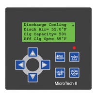
Daikin MicroTech II Installation And Maintenance Manual (70 pages)
Applied Rooftop Unit Controller
Brand:
Daikin
| Category:
Controller
| Size: 2.58 MB
Table of Contents
Table of Contents
2
Introduction
3
General Description
4
Component Data
4
Main Control Board (MCB)
6
Analog Inputs Terminal Blocks
7
Binary Inputs Terminal Blocks
7
Binary Outputs Terminal Blocks
7
RS-485 Communications Terminal Block
7
Power Supply Terminals
7
Keypad/Lcd Display Connection
7
Communication Modules
7
Bacnet/Ip Communication Module
7
Bacnet MS/TP Communications Module
8
Lonworks® Communication Modules
8
RS-232 Connection Port
9
15 VDC Supply Connection
9
Main Control Board Leds
9
Auxiliary Control Boards (CCB1, CCB2, EHB1, and ERB1)
10
Analog Inputs Terminal Block (J8)
11
Binary Inputs Terminal Blocks (J9 and J10)
11
Binary Outputs Terminal Blocks
11
RS-485 Communications Module
11
Power Supply Terminals (J1)
11
J7 Terminal Block
11
J2 Terminal Block
11
Main Control Board (MCB) Output Relays and Triacs
11
Auxiliary Control Boards (CCB1, CCB2, GCB1, EHB1, and ERB1) Output Relays
12
Keypad/Display
12
Remote Keypad Display Option
12
Temperature Sensors
13
Pressure Transducers
13
Humidity Sensors
13
Actuators
13
Variable Frequency Drives (Vfds)
13
Field Wiring
14
Field Output Signals
14
Remote Alarm Output
14
Fan Operation Output
14
VAV Box Output
15
Cooling Only Units
15
Cooling Only Units with Field Supplied Heat
15
Units with One-Stage Heat
15
Units with Modulating Heat
16
Staged Cooling Outputs
16
Field Analog Input Signals
16
Zone Temperature Sensor Packages
16
Zone Sensor Without Remote Set Point Adjustment
16
Zone Sensor with Remote Set Point Adjustment
17
Tenant Override (Timed)
17
External Discharge Air Reset Signal
18
External Outdoor Air Damper Reset Signal
18
Field Valve Actuator Feedback
19
Humidity Sensors
20
Humidity Sensor-Discharge Air Control (DAC) Unit
21
Field Binary Input Signals
21
Manual Cooling and Heating Enable
21
Cooling Enable
21
Heating Enable
21
Manual Unit Enable
21
External Time Clock or Tenant Override
21
Miscellaneous Output Signals
22
External Exhaust Fan Status
22
Service Information
23
Controller Inputs
23
Analog Inputs-Main Control Board (MCB)
23
Analog Inputs-Auxiliary Control Boards (CCB1, CCB2, GCB1, EHB1 & ERB1)
25
Binary Inputs-Main Control Board (MCB)
25
Binary Inputs-Auxiliary Control Boards (CCB1, CCB2, GCB1, EHB1 & ERB1)
25
Ccb1 & Ccb2 (7Rps, Rfs/Rcs, Rdt, Rpr & Rfr)
25
Gcb1 (Rds & Rah)
25
Ehb1
25
Erb1
25
Controller Outputs
26
Binary Outputs-Main Control Board (MCB)
26
Binary Outputs-Auxiliary Control Boards (CCB1, CCB2, GCB1, EHB1 & ERB1)
28
CCB1 and CCB2
28
Gcb1 (Rds & Rah)
33
Ehb1
33
Eerb1
34
Software Identification and Configuration
34
Main Control Board (MCB) Configuration
34
Main Control Board (MCB) Data Archiving
35
Typical Wiring Diagrams
36
Legend
36
Test Procedures
60
Troubleshooting Main Control Board (MCB)
60
MCB Battery
60
MCB Data Archiving
60
MCB "Cold" Reboot
60
MCB LED Power-Up Sequence
60
MCB LED Startup Error Codes
62
Battery Test
63
Flash CRC Tests
63
SRAM Test
63
Communication Port Tests
63
IP Register Test
63
Troubleshooting Auxiliary Control Boards (CCB1, CCB2, GCB1, EHB1 and ERB1)
64
Hardware Check
64
RS-485 Communication Card Status Leds
64
Troubleshooting Keypad/Display
64
Keypad/Display Power up Initialization
64
Troubleshooting Temperature Sensors
65
Troubleshooting Communications Modules
66
Bacnet/Ip Module
66
Bacnet MS/TP Module
66
Lonmark Modules
66
Troubleshooting Pressure Transducers
67
Parts List
68
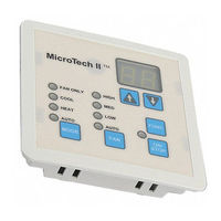
Daikin MicroTech II Operation And Maintenance Manual (44 pages)
Used with Daikin Classroom Unit Ventilator Model AVV - Floor-Mounted, Model AHV - Ceiling-Mounted
Brand:
Daikin
| Category:
Remote Control
| Size: 1.67 MB
Table of Contents
Table of Contents
3
Introduction
5
Acronyms/Abbreviations
6
Getting Started
8
Using the Keypad/Display
8
Display Format
8
Keypad Functions
8
Using the Keypad/Display
10
Changing Set Points
10
Menu Reference
10
State Programming
13
Description of Operation
13
UVC Unit Modes
14
OFF Mode (State 9)
15
Night Purge Mode (State 8)
16
Fan Only Mode (State 10)
16
Emergency Heat Mode (Super State)
17
Auto Mode
18
Cool Mode (Super State)
19
Special Purpose Unit Modes
22
Unit Mode Priority
23
Occupancy Modes
24
Occupied Mode
24
Unoccupied Mode
24
Standby Mode
24
Bypass Mode
24
Additional Occupancy Features
25
Networked Occupancy Sensor Capability
25
Unit-Mounted Time-Clock
25
Unit-Mounted Tenant Override Switch
25
Remote Wall-Mounted Sensor Tenant Override Switch
25
Remote Wall-Mounted Sensor Status LED
25
Space Temperature Set Points
26
Networked Set Point Capability
26
Networked Set Point Offset Capability
26
Networked Set Point Shift Capability
26
Networked Space Temperature Sensor Capability
26
Remote Wall-Mounted Sensor with +/-3°F Adjustment (Optional)
26
Remote Wall-Mounted Sensor with 55°F to 85°F Adjustment (Optional)
27
Effective Set Point Calculations
27
Proportional Integral (PI) Control Loops
29
Discharge Air Temperature Control
29
PI Control Parameters
30
Proportional Band
30
Integral Time
31
Indoor Air Fan Operation
31
Auto Mode
31
Occupied, Standby, and Bypass Operation
31
Unoccupied Operation
31
Cycle Fan
31
Off Delay
31
Outdoor Air Damper Operation
32
Minimum Position
32
Economizer Operation
32
Networked Space Humidity Sensor Capability
33
Networked Outdoor Humidity Sensor Capability
33
CO 2 Demand Controlled Ventilation (Optional)
33
Networked Space CO 2 Sensor Capability
34
ASHRAE Cycle II
34
Outdoor Air Fan Operation
34
Floating-Point Actuator Auto-Zero, Overdrive and Sync
35
External Binary Inputs
35
External Binary Input 1
35
External Binary Input 2
35
External Binary Outputs
36
External Binary Output 1
36
External Binary Output 2
36
External Binary Output 3
36
UVC Input and Output Table
37
Diagnostics and Service
38
Alarm and Fault Monitoring
38
Space Temp Sensor Failure (F0)
39
Outdoor Temp Sensor Failure (F6)
39
Discharge Air Temp Sensor Failure (F7)
39
Space Humidity Sensor Failure (Optional) (Fa)
39
Outdoor Humidity Sensor Failure (Optional) (Fb)
39
Space CO 2 Sensor Failure (Optional) (Fc)
39
Change Filter Indication (Ff)
39
EPROM Memory Indicator (Ee)
40
Configuration Display
40
Troubleshooting Temperature Sensors
40
Troubleshooting Humidity Sensors
41
Troubleshooting Carbon Dioxide (CO 2 ) Sensors
41
UVC Configuration Parameters
42
Advertisement
Daikin MicroTech II Installation And Maintenance Manual (24 pages)
BACnet MS/TP Communication Module
Brand:
Daikin
| Category:
Chiller
| Size: 3.78 MB
Table of Contents
Table of Contents
2
Introduction
3
Revision History
3
Notice
3
Software Revision
3
Reference Documents
3
Hazardous Information Messages
4
Features
4
Specifications
4
Component Data
5
Current Hardware
5
Light Emitting Diodes (Leds)
5
Status LED
6
Network LED
6
Bacnet Network Connector
6
8-Pin Header
6
S1, S2, and S3 Switches
6
Pushbutton
6
Previous Hardware
7
Light Emitting Diodes (Leds)
7
Status LED
7
Network LED
7
Bacnet Network Connector
7
8-Pin Header
7
P1, P2, and P3 Jumpers
7
Pushbutton
7
Installation
8
Installation and Mounting
8
Field Installation Kit
8
Installing a New Communication Module
8
Replacing a Communication Module
10
Network Configuration
12
Fi
12
Set up Network Communication
12
Getting Started
12
Bacnet Configuration Tool Interface Overview
12
The Configuration Tool as a Bacnet Device
12
How to Use These Instructions
12
Installation and Setup
13
Launch and Use the Bacnet Configuration Tool
14
Set Network Parameters
14
Verify Bacnet Communication
17
Download Bacnet Firmware Files
18
Change Bacnet Configuration Tool Addressing
18
Parameters
18
Bacnet MS/TP MAC Layer Select Options
19
Restart or Reset the Communication Module
20
Restart the Communication Module
20
Reset Factory Defaults When the Chiller Is off
20
Reset Factory Defaults When the Chiller Is on
20
Troubleshooting
21
.
21
Troubleshooting Procedures
21
Parts
22
Parts List
22
Advertisement
Related Products
Daikin Madoka
Daikin MicroTech III
Daikin MicroTech III DPS
Daikin MicroTech
Daikin MicroTech I
Daikin Mini-ZEAS LRLEQ-BY
Daikin Maverick I MPS H03C
Daikin AHT VENTO GREEN MC 375
Daikin Modular T Pro ATB
Daikin MKM95PV1G
Daikin Categories
Air Conditioner
Heat Pump
Remote Control
Chiller
Fan
More Daikin Manuals
Login
Sign In
OR
Sign in with Facebook
Sign in with Google
Upload manual
Upload from disk
Upload from URL