Sign In
Upload
Manuals
Brands
Control Techniques Manuals
Servo Drives
DIN1220025A
Control Techniques DIN1220025A Manuals
Manuals and User Guides for Control Techniques DIN1220025A. We have
1
Control Techniques DIN1220025A manual available for free PDF download: User Manual
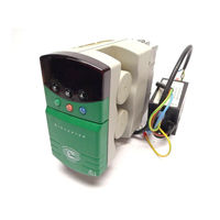
Control Techniques DIN1220025A User Manual (95 pages)
Variable Speed Drive for 3-phase induction motors 0.25kW to 0.75kW
Brand:
Control Techniques
| Category:
Servo Drives
| Size: 2.06 MB
Table of Contents
General Information
2
Table of Contents
3
1 Introduction
5
Advanced Functions
5
Bench-Testing the Dinverter
7
Methods of Control
7
Terminal Mode
7
Keypad Mode
7
2 Safety Information
8
Warnings, Cautions and Notes
8
Electrical Safety – General Warning
8
System Design
8
Risk Analysis
9
Motor
9
Adjusting Parameters
10
Safety of Personnel
10
3 Data
11
Power, Voltage and Current Ratings
11
Immunity
12
Emission
12
Power Drive Systems Standard EN61800–3
13
Heat Dissipation and Surge-Current
14
Optional RFI Filter (DIN1012F)
14
Conducted Emission
15
Maximum Ground Leakage Current
15
4 Installing the Drive
16
Electric Shock Risk
16
Fire Enclosure
16
Isolation Device
17
Stored Charge
17
Supply by Plug and Socket
17
Water Ingress
17
EMC Considerations
18
Routine EMC Precautions
18
Operation in the First Environment
18
Operation in the Second Environment
18
Environmental Requirements
19
Planning the Installation
20
Temperature De-Rating
20
Length of Motor Cable
20
RFI-Filter Ground-Leakage Current
20
Enclosure Layout
21
Recommended Layout for Routine EMC Precautions
22
Installing the Drive and Optional RFI Filter
24
Grounding the Drive Heatsink
24
Mounting the Earthing Spring
24
Mounting the Drive on a DIN-Rail
25
Fit Brackets for DIN-Rail Mounting
26
Mounting the RFI Filter on a DIN-Rail
27
Surface-Mounting the Drive
28
Surface-Mounting the RFI Filter
30
AC Supply Requirements
31
Ground Connections
31
Typical Sizes of the Power Cables
32
Type of Motor Cable
32
Interruption in the Motor Cable
32
Fuses
32
Fuse Ratings
33
AC Supply Disturbances – Use of Line Reactors
33
Typical Line-Reactor Values
34
Working in the Terminal Chamber of the Drive
34
Connector Sizes and Data
35
Connecting and Setting up an RFI Filter
37
Wiring Recommendations
39
Wiring Guidelines for Routine EMC Precautions
40
Key to Symbols
40
General Features
42
Wiring Guidelines for Compliance with EMC Emission Standards
44
Signal Connections for Operation in Keypad Mode
48
Signal Connections for Operation in Terminal Mode
48
Control Signal Connections
49
Parameters that Control the Functions of the Analog Inputs
50
Descriptions of the Signal Connections
50
0V Common
50
Analog Input 1
50
+10V Reference Output
51
Volt-Free Relay Contact
51
Digital Input F3
52
Digital Input F4
52
Digital Input F5
52
Digital Input/Output F1
52
Analog Output
53
Serial Communications Port
53
Analog Input 2
53
RS485 2-Wire Serial Communications Connections
55
Connecting a Remote Speed Reference
56
Remote Speed-Reference Connections
56
Connecting a Motor Thermistor to Terminals C4 and C5
56
Making Temporary Connections
58
Bench Testing the Drive
58
5 Programming Instructions
60
Electrical Connections
60
Introduction to the Display and Keypad
60
Special Features of the Parameters
60
Functions of the Settings of Parameter .00
61
Display and Keypad
61
The Four Display Modes
62
Keypad
62
Programming Keys
62
Control Keys
62
Procedures
63
Entering Parameter Mode and Returning to Status Mode
64
Display in Parameter Mode
64
Selecting a Parameter to Access
64
Increasing the Parameter Number (Parameter 0.01 Is Shown)
65
Changing the Value of a Parameter
65
Scrolling
65
Select a Parameter
65
Display in Edit Mode Showing the Value of a Parameter
66
Decreasing the Value of a Parameter
66
Making Large Changes in Value Quickly
66
Selecting the Next Most-Significant Digit
67
Decreasing the Value of the Flashing Digit
67
Reaching the Maximum or Minimum Value
68
Quick Selection from most to Least Significant Digit
68
Setting the Value at Zero
68
Setting the Value of a Parameter at Zero
68
Saving the New Value of a Parameter
69
Bench-Testing? Return to Default Value
69
Variations in Operation
69
Flashing and Non-Flashing Digits
69
Changing the Setting of a Bit Parameter
70
Selecting a Parameter in an Advanced Menu
70
–11 Display in Parameter Mode
70
Changing the Initial Parameter to be Displayed
71
Selecting a Different Menu
71
Restoring All Parameters to the Default Values
71
Saving the Default Values
71
6 Setting up the Drive for the Application
72
Preparation
72
Configuring the Drive for the Motor
73
Maximum Continuous Current
73
Checking Operation in Terminal Mode
74
Checking Operation in Keypad Mode
75
Making Adjustments
76
7 Menu 0 Parameters
77
Categories
77
Speed Clamp
80
Minimum Speed
80
Maximum Speed
80
Ramps
81
Speed Reference Selection
81
Current Limit
81
Boost Voltage
82
Monitoring
83
Motor Frequency
83
Deceleration Selectors
83
Stop-Mode
84
Select Torque Control
84
Skip Speed 1
85
Analog-Input Modes
85
Keypad Speed Reference Monitoring
85
Serial Communications
86
PWM Switching Frequency
87
Motor Parameters
87
Status
87
Security Status
87
8 Diagnostics
88
Status Messages
88
Warning Indications
89
When a Trip Occurs
89
Clearing a Trip
89
Changing a Parameter Value after a Trip Occurs
89
Trip Codes
90
Internal Trips
90
Introduction to the Security System
92
Features of the Security System
92
Logic Table for the Security System
93
Identifying the Security Status
94
Security Procedures
94
Unlock Standard Security
94
Set up User Security
94
Advertisement
Advertisement
Related Products
Control Techniques DIN1220037A
Control Techniques DIN1220055A
Control Techniques DIN1220075A
Control Techniques Dinverter A
Control Techniques Digitax ST
Control Techniques DeviceNet
Control Techniques Epsilon EP-P
Control Techniques M'Ax 403
Control Techniques M'Ax 406
Control Techniques M'Ax 409
Control Techniques Categories
Control Unit
DC Drives
Controller
Inverter
Servo Drives
More Control Techniques Manuals
Login
Sign In
OR
Sign in with Facebook
Sign in with Google
Upload manual
Upload from disk
Upload from URL