Sign In
Upload
Manuals
Brands
Contec Manuals
Computer Hardware
CNT24-4D(PCI)
Contec CNT24-4D(PCI) Manuals
Manuals and User Guides for Contec CNT24-4D(PCI). We have
1
Contec CNT24-4D(PCI) manual available for free PDF download: User Manual
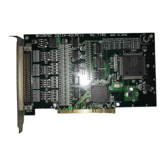
Contec CNT24-4D(PCI) User Manual (70 pages)
24Bit Differencial Up/Down Counter Board for PCI
Brand:
Contec
| Category:
Computer Hardware
| Size: 3.46 MB
Table of Contents
Trademarks
2
Product Configuration
3
Table of Contents
4
1 Introduction
10
Features
10
Limited Three-Year Warranty
11
How to Obtain Service
11
Liability
11
Handling Precautions
12
About the Manual
13
2 Component Locations and Setting
14
Component Locations
14
Figure 2.1. Component Locations
14
Setting the Board ID
15
Setting Procedure
15
Figure 2.2. Board ID Settings (SW1)
15
Setting One-Shot Pulse Output Signals
16
Figure 2.3. Switch for Setting One-Shot-Pulse Output Signals
16
Table 2.1. One-Shot-Pulse Output Signal Settings
16
Setting Terminators
17
Figure 2.4. Terminator Setting Switches
17
Table 2.2. Terminator Settings
17
3 Board Setup
18
Use CONTEC Windows Software Products
18
When Not Using CONTEC Software for Windows
19
For Windows 98 Systems
19
For Windows 95 Systems
23
For Other os Systems
28
4 Connection with External Devices
30
Interface Connector
30
Connecting the Interface Connector
30
Figure 4.1. Connecting the Interface Connector
30
Figure 4.2. Connectors in Use
30
Interface-Connector Signal Assignment
31
Figure 4.3. Interface-Connector Signal Assignment
31
PCB96WS and CCB-96 Signal Assignment
32
Figure 4.4. PCB96WS and CCB-96 Signal Assignment
32
Connection of External Signals
33
Line Receiver Input Circuit and an Example Connection
33
Figure 4.5. Line-Receiver Input Circuit and an Example Connection
33
TTL-Level Input Circuit and an Example Connection
34
Output Circuit and an Example Connection
34
Figure 4.7. Open-Collector Output Circuit and an Example Connection
35
Example Connection with a Rotary Encoder
36
Figure 4.9. Example Connection with a Rotary Encoder
36
Figure 4.10. Example Connection with a Rotary Encoder (TTL Input)
36
Measures against Voltage Surges
37
Figure 4.11. Example Measures against Voltage Surges
37
5 I/O Port Bit Assignment
38
Figure 5.1. Output Port
38
Figure 5.2. Input Port
38
Setting Data
39
Count Flow
40
Figure 5.3. Count Flow
40
Operation Commands
41
Table 5.1. Output Commands
41
Table 5.2. Input Commands
42
Description of Output Commands
43
Initial Count Value (Command CH0:00H:, CH1:05H:, CH2:0AH:, CH3:0FH)
43
Operation Mode (Command CH0:01H:, CH1:06H:, CH2:0BH:, CH3:10H)
43
Table 5.3. Counter Operation Modes
44
Table 5.4. Switching Counting Directions
44
Each Counter Operating Mode
45
Figure 5.4. Example Counting During 2-Phase Input
45
Figure 5.5. Example Counting During Single-Phase Input
45
Figure 5.6. Example Counting During Single-Phase Input with Gate Control Attached
46
Figure 5.7. Example Counting During Synchronous Clear
46
Figure 5.8. Example Counting During Asynchronous Clear
47
Figure 5.9. Example Counting When Count Input Multiplication Is Set
48
Phase Z/CLR Input (Command CH0:02H, CH1:07H, CH2:0CH, CH3:11H)
49
Figure 5.10. Phase Z Enable Frequency ZSEL=0
49
Table 5.5. Phase Z Input Mode
49
Compare Register (Command CH0:03H, CH1:08H, CH2:0DH, CH3:12H)
50
Digital Filter (Command CH0:04H, CH1:09H, CH2:0EH, CH3:13H)
51
Figure 5.11. Digital Filter
51
Count Value Latch (Command 14H)
52
Table 5.6. Digital Filter Clock Settings
52
Interrupt Mask (Command 15H)
53
Sense Reset (Command 16H)
53
Programmable Timer (Command Timer Data:17H, Timer Start:18H)
54
One-Shot Pulse (Command 19H)
55
Table 5.7. Relationship between Programmable Timer Setting Data and Timer Interrupt Cycles
55
Table 5.8. Relationship between Specified One-Shot-Pulse Width Data and Pulse Widths
56
General-Purpose Input Signal Select (Command 1AH)
57
Description of Input Commands
58
Count Read (Command CH0:00H, CH1:05H, CH2:0AH, CH3:0FH)
58
Status Data (Command CH0:01H, CH1:06H, CH2:0BH, CH3:10H)
58
Interrupt Mask (Command 15H)
60
Sense Port (Command 16H)
60
General-Purse Input Signal Select (Command 1AH)
61
Initialization
62
Table 5.9. Initialized State
62
6 Board Specifications
64
Block Diagram
64
Figure 6.1. Block Diagram
64
Specifications
65
Table 6.1. Specifications
65
7 Index
68
Advertisement
Advertisement
Related Products
Contec CNT32-4MT
Contec CNT-3204MT-LPE
Contec COM-2(PCI)
Contec COM-8(PCI)
Contec COM-1(PM)
Contec CONPROSYS nano CPSN-MCB271-S1-041
Contec CONPROSYS
Contec CONPROSYS CPS-PCS341MB-DS1-1201
Contec CONPROSYS Linux SDK
Contec COM-1D(PM)
Contec Categories
I/O Systems
PCI Card
Medical Equipment
Desktop
Computer Hardware
More Contec Manuals
Login
Sign In
OR
Sign in with Facebook
Sign in with Google
Upload manual
Upload from disk
Upload from URL