Sign In
Upload
Manuals
Brands
Comtech EF Data Manuals
Modem
CDMR-570L
Comtech EF Data CDMR-570L Manuals
Manuals and User Guides for Comtech EF Data CDMR-570L. We have
1
Comtech EF Data CDMR-570L manual available for free PDF download: Installation And Operation Manual
Comtech EF Data CDMR-570L Installation And Operation Manual (512 pages)
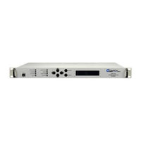
70/140 MHz Satellite Modem, L-Band Satellite Modem, Reduced Chassis Depth L-Band Satellite Modem
Brand:
Comtech EF Data
| Category:
Modem
| Size: 11.12 MB
Table of Contents
Installation and Operation Manual
1
Table of Contents
11
About this Manual
31
Conventions and References
31
Patents and Trademarks
31
Preface
31
Reporting Comments or Suggestions Concerning this Manual
31
Examples of Multi-Hazard Notices
32
Metric Conversion
32
Recommended Standard Designations
32
Warnings, Cautions, and Notes
32
Electrical Installation
33
Electrical Safety and Compliance
33
Fuses
33
Safety and Compliance
33
European Union Electromagnetic Compatibility (EMC) Directive (2004/108/EC)
34
European Union Radio Equipment and Telecommunications Terminal Equipment (R&TTE) Directive (1999/5/EC) and en 301 489-1
34
Operating Environment
34
European Union Low Voltage Directive (LVD) (2006/95/EC)
35
European Union Rohs Directive (2002/95/EC)
35
CE Mark
36
European Union Telecommunications Terminal Equipment Directive (91/263/EEC)
36
Limitations of Warranty
36
Warranty Policy
36
Exclusive Remedies
37
Contacting Comtech EF Data
38
Getting Help
38
Returning a Product for Upgrade or Repair
39
Chapter 1. INTRODUCTION
41
Overview
41
Figure 1-1. CDM-570/570L Satellite Modem
41
Functional Description
42
Features
43
Physical Description
43
Compatibility
43
Major Assemblies
43
Dimensional Envelope
44
Figure 1-2. CDM-570/570L Dimensional Envelope
44
Physical Features
45
Front Panel
45
Rear Panel
45
Figure 1-3. Front Panel View
45
Figure 1-4. Rear Panel View
45
Table 1-1. Summary of CDM-570/570L Rear Panel Connectors
46
Hardware Options
47
Data Interfaces
47
Verification
47
Aupc
47
Edmac
48
Updating Modem Firmware
48
Fully Accessible System Topology (FAST)
48
Fast System Theory
49
Supporting Hardware and Software
50
Summary of Specifications
51
Modulator
51
Demodulator
53
Automatic Uplink Power Control
55
Data and Miscellaneous Interfaces
56
Data Rate Ranges
56
Miscellaneous
57
Approvals
58
Chapter 2. INSTALLATION and STARTUP
59
Unpacking and Inspecting the Shipment
59
Figure 2-1. Unpacking and Inspecting the Shipment
59
Rack-Mounting the CDM-570/570L
60
Figure 2-2. Installation into a Rack Enclosure
61
Installing the Optional Rear-Mounting Support Brackets Kit
62
Figure 2-3. Optional Rear-Mounting Support Brackets Kit Installation
62
Initial Configuration
63
Verifying Operation (if Loopback Test)
63
Connecting External Cables
64
Chapter 3. REAR PANEL CONNECTORS and PINOUTS
65
Connector Overview
65
Figure 3-1. CDM-570/570L Rear Panel
65
Table 3-1. Rear Panel External Connections
66
IF Connections
67
Rx if Connectors
67
Tx if Connectors
67
IF Connections
68
Data Interface Connector, DB-25F
68
Table 3-2. Data Interface Connector Pin Assignments
68
Connections
69
Balanced E1/T1 Interface Connector, DB-15F
69
Table 3-3. Balanced G.703 Interface Connector Pin Assignments
69
E1/T1 RJ-48 Connection Via G.703 Balanced Interface Connector
70
Unbalanced Interface Connectors (Tx/Rx), 75Ω BNC
70
10/100 Baset Ethernet Connections
71
10/100 Baset Ethernet Management (M&C) Port, RJ-45 (Standard)
71
10/100 Baset Ethernet Traffic Port, RJ-45 (with Optional IP Module Only)
71
Table 3-4. Typical Ethernet Interface Port Pin Assignments
71
Utility Connections
72
Remote Control Interface Connector, DB-9M
72
Form-C Traffic Alarms Connector, DB-15M
72
Table 3-5. Remote Control Interface Connector Pin Assignments
72
1:1 Control Interface Connector, DB-9F
73
Table 3-6. Alarm Interface Connector Pin Assignments
73
Table 3-7. 1:1 Control Interface Connector Pin Assignments
73
Ext Ref Connector, BNC
74
Async- Serial Console, RJ-11 (with Optional IP Module Only)
74
Table 3-8. ASYNC-Serial Console Connector Pin Assignments
74
Power and Ground Connections
75
Alternating Current (AC) Power Connector (Standard)
75
Optional Direct Current (DC) Power Connector
75
Or 48V DC Units - CDM-570 or CDM-570L Units
75
DC Units - CDMR-570L Unit Only
76
Ground Connector
76
Chapter 4. UPDATING FIRMWARE
77
Updating Firmware Via Internet
77
About Firmware Files, Naming, Versions and Formats
77
Preparation for the Base Modem Ethernet FTP Upload Procedure
79
Base Modem Bulk Firmware Update - Ethernet FTP Upload Procedure
80
Ethernet IP Module FTP Upload Procedure
82
USB Procedure
85
Chapter 5. FRONT PANEL OPERATION
87
Introduction
87
Figure 5-1. Front Panel View (CDM-570L Shown)
87
LED Indicators
88
Keypad
89
Figure 5-2. CDM-570/570L - Front Panel Keypad
89
Vacuum Fluorescent Display (VFD)
90
CDM-570/570L Front Panel Menus
90
Opening Screen
90
SELECT: (Main) Menu
91
Figure 5-3. CDM-570/570L Menu Tree (FW Ver. 1.6.15)
92
SELECT:) Config (Configuration) Menus
93
CONFIG: Rem (Remote Control)
94
CONFIG: Remote Control) Serial
94
CONFIG:) Remote Control: Ethernet
95
Snmp Communities
96
CONFIG: All
97
CONFIG: Tx (Transmit)
98
CONFIG: Tx) FEC (FEC Type)
99
CONFIG: Tx) Mod (Modulation)
99
Important Note
99
CONFIG: Tx) Code (Code Rate)
100
CONFIG: Tx) Data (Data Rate)
101
CONFIG: Tx) Frq (Frequency)
102
CONFIG: Tx) On/Off
102
CONFIG: Tx) Pwr (Power)
103
CONFIG: Tx) Scram (Scrambling)
104
CONFIG: Tx) Clk (Clock Source)
105
CONFIG: Tx) Inv (Inversion Functions)
106
CONFIG: Rx (Receive)
106
CONFIG: Rx) FEC (FEC Type)
107
CONFIG: Rx) dem (Demodulation)
108
CONFIG: Rx) Code (Code Rate)
108
CONFIG: Rx) Data (Data Rate)
109
CONFIG: Rx) Frq (Frequency)
110
CONFIG: Rx) Acq (Acquisition Range)
110
CONFIG: Rx) Descram (Descrambling)
111
CONFIG: Rx) Buf (Buffer)
111
CONFIG: Rx) Inv (Inversion Functions)
112
CONFIG: Rx) E /N
112
CONFIG: Cex (G.703 Clock Extension)
113
CONFIG: Frame (Framing Mode)
113
CONFIG: Framing Mode) EDMAC or EDMAC-2
113
CONFIG: Intfc (Interface)
115
CONFIG: Interface) RS422 or V.35 or RS232
115
CONFIG: Interface) IP
115
CONFIG: Interface) G.703
116
CONFIG: Ref (Reference)
117
CONFIG: Mask
117
CONFIG: Alarm Mask) Transmit
117
CONFIG: Alarm Mask) Receive
118
CONFIG: Alarm Mask) Ref
118
CONFIG: Alarm Mask) BUC (CDM-570L ONLY)
119
CONFIG: Alarm Mask) LNB (CDM-570L ONLY)
119
Config: Odu (CDM-570L Only)
119
SELECT: Monitor
120
MONITOR: Alarms
120
MONITOR: Live Alarms) Unit
121
MONITOR: Live Alarms) Receive (Receive Traffic Status)
121
MONITOR: Live Alarms) Transmit (Transmit Traffic Status)
121
MONITOR: Rx-Params
121
MONITOR: Event-Log (Stored Events)
122
MONITOR: Stored Events) View
122
MONITOR: Stored Events) Clear-All
122
MONITOR: Stats (Link Statistics)
122
MONITOR: Link Statistics) View
123
MONITOR: Link Statistics) Clear-All
124
MONITOR: Link Statistics) Config (Configure)
124
Monitor: Aupc
124
Monitor: Odu (CDM-570L Only)
125
Select: Test
125
Figure 5-4. Loopback Modes
126
SELECT: Info
127
INFO: All
127
INFO: Tx (Transmit)
127
INFO: Rx (Receive)
128
INFO: Buf (Buffer)
128
INFO: Frame (Framing and EDMAC)
128
INFO: Intfc (Interface)
129
INFO: Rem (Remote Control)
129
INFO: Msk (Alarm Mask)
129
INFO: Ref (Frequency Reference)
130
INFO: ID (Circuit ID)
130
INFO: 1:1 (1:1 Redundancy)
130
SELECT: Save/Load
130
Save/Load Configuration: Save
130
Save/Load Configuration: Load
131
SELECT: Utility
132
UTIL: Buffer (Buffer Re-Center)
132
UTIL: Clock (Set Real-Time Clock)
132
UTIL: Ref (Reference)
132
UTIL: Ref Adjust
133
UTIL: Ref Warm-Up Delay
133
UTIL: ID (Circuit ID)
134
UTIL: 1:1 (Manual 1:1 Switchover)
134
UTIL: VFD (Video Fluorescent Display Brightness)
134
UTIL: Firmware
135
UTIL: Firmware Image) Info
135
UTIL: Firmware Image) Select
135
UTIL: FAST (FAST Code Options)
136
UTIL: FAST) Cnfg (FAST Configuration)
136
UTIL: FAST) View
138
SELECT: ODU Menus (CDM-570 ONLY)
138
Chapter 6. Ethernet-Based Remote Product Management
139
Introduction
139
Ethernet Management Interface Protocols
139
HTTP (Web Server) Interface
140
HTTP Interface - Typical Operational Features
140
Interface Access
140
Navigation
141
Page Sections
141
Home | Home .................................................................................................................................... 7–5
141
Home | Contact ................................................................................................................................. 7–6
141
Home | Support ................................................................................................................................. 7–7
141
Admin | Access ................................................................................................................................. 7–8
141
Admin | Remote .............................................................................................................................. 7–10
141
Execution Buttons
142
Feature Selection
142
Text or Data Entry
142
SNMP Interface
142
Management Information Base (MIB) Files
143
SNMP Community Strings
144
SNMP Traps
144
Mib-II
145
Private MIB
145
Telnet Interface
146
Telnet Operation Via Hyperterminal
147
Chapter 7. BASE MODEM HTTP INTERFACE
149
Overview
149
Base Modem HTTP Interface Introduction
149
Interface Access
150
Menu Tree and Splash Page
151
Config MDM | Modem Utilities ..................................................................................................... 7–12
151
Config MDM | AUPC ..................................................................................................................... 7–14
151
Stats | Modem Status ...................................................................................................................... 7–15
151
Stats | Modem Logs ........................................................................................................................ 7–16
151
Figure 7-1. CDM-570 "Splash" Page
151
CDM-570L Menu Tree and Splash Page
152
Figure 7-2. CDM-570L "Splash" Page
152
HTTP Interface
153
Home
153
Home | Home
153
Maint (Maintenance) | Unit Info Page ................................................................................ 7–17
153
Figure 7-3. Satellite Modem Home Page (CDM-570L Shown)
153
Home | Contact
154
Figure 7-4. Home | Contact Page
154
Home | Log off ........................................................................................................... 13–23
154
Home | Support ........................................................................................................... 13–22
154
Admin | Access ........................................................................................................... 13–28
155
Admin | Features ......................................................................................................... 13–29
155
Admin | Mode ............................................................................................................. 13–25
155
Admin | Remote .......................................................................................................... 13–31
155
Admin | Summary ....................................................................................................... 13–24
155
Figure 7-5. Home | Customer Support Page
155
Admin
156
IP | Interface ................................................................................................................ 13–37
156
IP | Routes ................................................................................................................... 13–40
156
IP | Multicast ............................................................................................................... 13–42
156
IP | Qos Mode ............................................................................................................. 13–44
156
IP | Qos (Quality of Service) Page ............................................................................. 13–45
156
Figure 7-6. Admin | Access Page
156
Figure 7-7. Admin | Remote Page
158
Config MDM (Configure Modem)
159
Config MDM | Modem
159
Figure 7-8. Config MDM | Modem Page
159
Figure 7-9. Config MDM | Modem Utilities Page
160
Maint | Operations ....................................................................................................... 13–62
162
Maint | Reboot ............................................................................................................. 13–64
162
Maint | Save ................................................................................................................ 13–63
162
Maint | Unit Info ......................................................................................................... 13–61
162
Stats | Compression ..................................................................................................... 13–60
160
Stats | Ethernet ............................................................................................................ 13–56
160
Stats | Qos ................................................................................................................... 13–58
160
Stats | Routes ............................................................................................................... 13–57
160
Stats | WAN ................................................................................................................ 13–59
160
Figure 7-10. Config MDM | AUPC Page
162
Stats
163
Figure 7-12. Stats | Modem Status Page
163
Figure 7-13. Stats | Modem Logs Page
164
ODU (Outdoor Unit)
165
Maint (Maintenance) | Unit Info Page
165
Chapter 8. Forward Error Correction Options
168
Table 8-1. Viterbi Decoding Summary
168
Table 8-2. Concatenated RS Coding Summary
169
Table 8-3. 8-PSK/TCM Coding Summary
170
Introduction
171
Viterbi
171
Turbo Product Codec (Hardware Option)
171
TPC Modes Available in the CDM-570/570L
171
Table 8-4. Available TPC Modes
171
8-QAM Modulation
172
End-To-End Processing Delay
172
Table 8-5. Turbo Product Coding Processing Delay Comparison
172
Comparison of All TPC Modes
173
Uncoded Operation (no FEC)
174
Table 8-6. Turbo Product Coding Summary
174
Rates above 2.5 Msymbols/Sec
175
Figure 8-1. Viterbi Decoding
176
Figure 8-2. Viterbi with Concatenated RS Outer Code
177
Figure 8-3. 8-PSK/TCM Rate 2/3 with Concatenated RS Outer Code
178
Figure 8-4. Rate 3/4 QPSK/OQPSK, 8-PSK and 16-QAM Turbo
179
Figure 8-5. Rate 7/8 QPSK/OQPSK, 8-PSK and 16-QAM Turbo
180
Figure 8-6. Rate 21/44 QPSK, Rate 0.95 QPSK and Rate 0.95 8-PSK Turbo
181
Figure 8-7. Rate 21/44 BPSK and Rate 5/16 BPSK Turbo
182
Figure 8-8. Rate 3/4 and Rate 0.95 8-QAM Turbo
183
Figure 8-9. Rate 7/8 8-QAM Turbo
184
Figure 8-10. 16-QAM Viterbi, Rate 3/4 and Rate 7/8 with 220,200 RS Outer Code
185
Figure 8-11. Differential Encoding – no FEC, no Scrambling
186
Chapter 9. AUTOMATIC UPLINK POWER CONTROL (AUPC)
187
Introduction
187
Setting AUPC Parameters
188
Max Range
188
Target E B /N
188
Alarm
188
Demod Unlock
189
Compensation Rate
189
Monitoring
189
CDM-570/570L Satellite Modem with Optional IP Module Revision
190
Chapter 10. CLOCKING MODES
191
Introduction
191
Transmit Clocking
192
Internal Clock
192
Tx Terrestrial
192
Rx Loop-Timed, Rx=Tx
192
Rx Loop-Timed, Rx<>Tx (Asymmetric Loop Timing)
192
Receive Clocking
193
Buffer Disabled (Rx Satellite)
193
Buffer Enabled, Tx=Rx
193
Buffer Enabled, Rx<>Tx
193
Notes
193
X.21 Notes
193
Figure 10-1. Tx Clock Modes
194
Figure 10-2. Rx Clock Modes
195
Clock Extension
196
Clock Extension Mode 1
196
G.703 Clock Extension
196
Clock Extension Mode 2
197
Clock Extension Mode 3
197
Figure 10-3. G.703 Clock Extension Mode 1
198
Figure 10-4. G.703 Clock Extension Mode 2
199
Figure 10-5. G.703 Clock Extension Mode 3
200
Chapter 11. EDMAC CHANNEL
201
Theory of Operation
201
M&C Connection
202
Setup Summary
203
Chapter 12. OFFSET QPSK OPERATION
205
Chapter 13. Ethernet Ip Module Interface
207
Introduction
207
Major Assemblies
207
Ethernet IP Module Standard Features
207
10/100Baset Ethernet Interface
208
Network-Based Management
208
Remote Software/Firmware Upgrade Via FTP
208
Configuration Backup and Restore Via FTP
209
Event Logging to Capture All IP Module Activity
209
Detailed Statistics of IP Traffic
209
IGMP Support for Multicast
209
Static IP Routing for Unicast and Multicast
209
Managed Switch Mode
210
Managed Switch Mode Operation
210
K.4.1.2.1 ODU | Config
210
Streamline Encapsulation
212
Table 13-1. Streamline Encapsulation
212
Combined Working Mode
213
IP Module Optional Features
214
CDM-570/570L IP Module Demo Mode
214
3Xdes Encryption with Ability to Change Keys
215
IP Header Compression
215
Payload Compression
216
ADLC Vs. LZS Compression Comparison
216
Quality of Service
217
Maximum Bandwidth/Priority Qos Mode
217
Minimum/Maximum Bandwidth Qos Mode
220
Diffserv Qos Mode
221
IP Module Specifications - Supported Rfcs and Protocols
222
IP Module HTTP Interface
223
Interface Access
223
IP Module HTTP Interface "Splash" Page
224
Figure 13-1. CDM-570/570L IP Module HTTP Interface "Splash" Page
224
IP Module HTTP Interface Menu Tree
225
K.4.1.2.2 ODU | Status
225
Revision
225
HTTP Interface
226
Home
226
Home | Home
226
Figure 13-2. Home | Home Page
226
Home | Contact
227
Figure 13-3. Home | Contact Page
227
Home | Support
228
Figure 13-4. Home | Customer Support Page
228
Home | Log off
229
Figure 13-5. Info | Logoff Page
229
Admin
230
Admin | Summary
230
Figure 13-6. Admin |Summary Page
230
Admin | Mode
231
Figure 13-7. Admin | Mode Page (Prior to Firmware Ver. 1.6.#)
231
Figure 13-8. Admin | Mode Page (Firmware Ver. 1.6.# and Later)
232
Admin | Access
234
Figure 13-9. Admin | Access Page
234
Admin | Features
235
Figure 13-10. Admin | Features Page
235
Admin | Remote
237
Figure 13-11. Admin | Remote Page
237
Admin | Encryption
238
Figure 13-12. Admin | Encryption Page
238
Modem
239
Modem | Modem
239
Figure 13-13. Modem | Modem Page
239
Modem | Utilities
240
Figure 13-14. Modem | Utilities Page
240
Modem | Status
241
Figure 13-15. Modem | Status Page
241
Modem | Logs
242
Figure 13-16. Modem | Logs Page
242
IP | Interface
243
Figure 13-17. IP | Interface Page
243
IP | Routes
246
Figure 13-18. IP | Routes Page
246
IP | Multicast
248
Figure 13-19. IP | Multicast Page
248
IP | Qos Mode
250
Figure 13-20. IP | Qos Mode Page
250
IP | Qos (Quality of Service) Page
251
IP | Qos (Maximum Bandwidth/Priority Mode)
251
Figure 13-21. IP | Qos Page (Max/Priority Mode)
251
IP | Qos (Minimum/Maximum Bandwidth Mode)
253
Figure 13-22. IP | Qos Mode Page (Min/Max Mode)
253
IP | Qos (Diffserv Mode)
255
Figure 13-23. IP | Qos Mode Page (Diffserv Mode)
255
IP | Qos (VLAN - Priority/Maximum Bandwidth Mode)
256
Figure 13-24. IP | Qos Mode Page (VLAN – Priority/Max Mode)
256
Ip | Arp
257
Figure 13-25. IP | ARP Page
257
Ip | Vlan
258
Figure 13-26. IP | VLAN Page
258
Ip | Igmp
260
Figure 13-27. IP | IGMP
260
IP | Redundancy
261
Figure 13-28. IP | Redundancy Page
261
Stats (Statistics)
262
Stats | Ethernet
262
Figure 13-29. Stats | Ethernet Page
262
Stats | Routes
263
Figure 13-30. Stats | Routes Page
263
Stats | Qos
264
Figure 13-31. Stats | Qos Page
264
Stats | WAN
265
Figure 13-32. Stats | WAN Page
265
Stats | Compression
266
Figure 13-33. Stats | Compression Page
266
Maint (Maintenance)
267
Maint | Unit Info
267
Figure 13-34. Maint | Unit Info Page
267
Maint | Operations
268
Figure 13-35. Maint | Operations Page
268
Maint | Save
269
Figure 13-36. Maint | Save Page
269
Figure 13-37. Maint | Reboot Page
270
Maint | Reboot
270
Chapter 14. ETHERNET IP MODULE - CLI and TELNET OPERATION
271
Overview
271
Interface Access
271
CLI Menu
272
Figure 14-1. Main Menu Page
273
Main Menu Page
273
Figure 14-2. Administration Page
274
Administration Page
274
Figure 14-3. Name/Password Configuration Page
276
Name/Password Configuration Page
276
Figure 14-4. Access Lists Page
277
Access Lists Page
277
Figure 14-5. Feature Configuration Page
278
Feature Configuration Page
278
Figure 14-6. 3Xdes Encrypt Configuration Page
281
3Xdes Encrypt/Decrypt Configuration Page
281
Figure 14-7. SMTP Configuration Page
283
SMTP Configuration Page
283
Figure 14-8. SNMP Configuration Page
284
SNMP Configuration Page
284
Working Mode
285
Managed Switch Multicast Option
286
Header/Payload Compression Refresh Rate
286
Figure 14-9. Interface Configuration Page
287
Payload Compression Refresh Rate
287
Telnet Timeout
287
Interface Configuration Page
287
Figure 14-10. Ethernet Interface Page
288
Ethernet Interface Page
288
VLAN Table
289
Figure 14-11. VLAN Table
289
Figure 14-12. Satellite/Hdlc Interface Page
290
Satellite/Hdlc Interface Page
290
Figure 14-13. Receive HDLC Channel Addresses Page
291
Receive HDLC Channel Addresses Page
291
Figure 14-14. Qos Configuration Page
292
Qos (Quality of Service) Configuration Page
292
Figure 14-15. Qos Rules Configuration Page (Max/Priority Mode)
293
Qos Rules Configuration Page - Max/Priority Mode
293
Figure 14-16. Qos Rules Configuration Page (Min/Max Mode)
295
Qos Rules Configuration Page - Min/Max Mode
295
Figure 14-17. Diffserv Rules Configuration Page
296
Diffserv Rules Configuration Page
296
Figure 14-18. Route Table Configuration Page
297
Route Table Configuration Page
297
Figure 14-19. Protocol Configuration Page
300
Protocol Configuration Page
300
Figure 14-20. IGMP Information Page
301
IGMP Information Page
301
Figure 14-21. ARP Table Utilities Page
303
ARP Table Utilities Page
303
Figure 14-22. Brouter Configuration Page
304
Brouter Configuration Page
304
Figure 14-23. Vipersat Configuration Page
306
Vipersat Configuration Page
306
Figure 14-24. Modem Parameters Page
307
Satellite Modem Page
307
Figure 14-25. Modem Configuration Page
308
Configuration Page
308
Tx Configuration Page
309
Rx Configuration Page
311
Figure 14-28. Framing Mode Configuration Page
313
Framing Mode Configuration
313
Figure 14-29. Data Interface Configuration Page
314
Data Interface Configuration
314
Figure 14-30. Reference Configuration Page
315
Reference Configuration Page
315
Figure 14-31. Alarm Mask Configuration Page
316
Alarm Mask Configuration
316
Figure 14-32. Block up Converter (BUC) Configuration Page
317
Block up Converter (BUC) Configuration
317
Figure 14-33. Low Noise Block Converter (LNB) Configuration Page
318
Low Noise Block Converter (LNB) Configuration
318
1:1 Redundancy Configuration Page
319
Figure 14-34. 1:1 Redundancy Configuration Page
319
Figure 14-35. Operations and Maintenance Page
320
Operations and Maintenance Page
320
Figure 14-36. Unit Information Page
322
Figure 14-37. Statistics Menu
323
Statistics Page
323
Figure 14-38. IP Statistics Page
324
IP Routing Statistics Page
324
Figure 14-39. Filter/Drop Statistics Page
325
Filter/Drop Statistics Page
325
Figure 14-40. Qos Statistics Page
328
Qos Statistics Page
328
Figure 14-41. Ethernet Statistics Page
329
Ethernet Statistics Page
329
Figure 14-42. WAN Statistics Page
330
WAN Statistics
330
Figure 14-43. Compression Statistics Page
332
Compression Statistics
332
Figure 14-44. CPU Statistics Page
333
Figure 14-45. VLAN Statistics Page
333
CPU Statistics
333
VLAN Statistics
333
Figure 14-46. Event Log Page
334
Event Log Page
334
Figure 14-47. Database Operations Page
336
Database Operations Page
336
Figure 14-48. Diagnostics Page
337
Diagnostics Page
337
Figure 14-49. Logout Via Telnet Session
338
Telnet Session - Logout Option
338
Appendix A. CABLE DRAWINGS
339
Overview
339
To EIA-422/449 Data Cable
340
To V.35 DCE Conversion Cable
341
Appendix B. E B /NMEASUREMENT
343
Appendix B. EMEASUREMENT
343
Appendix C. FAST ACTIVATION PROCEDURE
347
FAST System Overview
347
FAST Activation Procedure
348
Record Modem Serial Number
348
View Currently Installed Features
348
Order FAST Options
348
Enter FAST Access Code
349
Enable / Disable Demo Mode
350
Appendix D. SERIAL REMOTE CONTROL
351
Overview
351
Basic Protocol
352
Packet Structure
353
Start of Packet
353
Target Address
353
Address Delimiter
354
Instruction Code
354
Instruction Code Qualifier
354
Optional Message Arguments
356
End of Packet
356
Remote Commands / Queries
357
Transmit (Tx) Commands and Queries
359
Receive (Rx) Commands and Queries
364
Unit Commands and Queries
368
Bulk Commands and Queries
379
BUC Commands and Queries (CDM-570L ONLY
381
LNB Commands and Queries (CDM-570L ONLY
384
Appendix E. CDM/CDD Nmcs Protocol - Rev 1.0
387
Revision History
387
Introduction
387
Architecture
388
Command Set Introduction
388
Telnet Interface
388
Basic Protocol
388
Instruction Code Qualifier
390
Optional Message Arguments
392
Row Index
392
Optional Argument Lists
393
End of Packet
393
IP Commands and Queries
395
Admin Commands and Queries
395
Interface Commands and Queries
402
Qos Commands and Queries
403
Protocol Commands and Queries
406
Operations and Maintenance Commands and Queries
408
Redundancy Queries
410
Routing Commands and Queries
411
Statistics Commands and Queries
413
WAN Stats
413
IP Statistics Commands and Queries
414
Ethernet Statistics Commands and Queries
416
Quality of Service (Qos) Statistics Commands and Queries
417
PARAM Files
418
Appendix F. Ip Quick-Start Guide
427
Quick-Start Guide Introduction
427
Getting Started
427
Equipment List
427
Equipment Setup
428
Transmit and Receive if Configuration
428
Serial Console Port Command Line Interface (CLI) Configuration
428
CLI Main Menu
429
Restoring Factory Default Configuration
429
Managed Switch Point-To-Point System Configuration
430
PC Configuration
430
CDM-IP Configuration - Setting IP Address(es
430
Router Mode Point-To-Point System Configuration
431
PC Configuration
431
Setting CDM-IP Modems to Router Mode Operation
432
Setting IP Address(es
432
Set Route Table Entries
432
Troubleshooting IP Module
434
Managed Switch Mode Troubleshooting
434
Router Mode Troubleshooting
436
Overview
437
Modem Compatibility
437
IP Module Working Modes
438
Working Modes - HDLC Encapsulation
438
Working Modes - Streamline Encapsulation
439
Managed Switch Mode
439
Figure G-1. Managed Switch Mode
441
Router Modes
442
Figure G-2. Router Point-To-Point Working Mode
442
G.3.4.2 Router Mode - Point-To-Multipoint
443
Figure G-3. Router Point-To-Multipoint Working Mode W/Hdlc
443
Figure G-4. Router Point-To-Multipoint Mode with Streamline Encapsulation
444
G.3.4.3 Router Mode (Brouter Enabled) - Point-To-Multipoint with VLAN Matching Filters
447
Sample Network #1 - VLAN Filtering Disabled
447
Sample Network #2 - VLAN Filtering Enabled
448
Brouter Mode with VLAN Filtering Configuration
448
Figure G-5. Brouter Point-To-Multipoint Working Mode W/Vlan Filtering
451
Appendix H. IP REDUNDANCY
453
Introduction
453
CRS-XXX 1:1 Redundancy Switch Functional Description
453
70/140 Mhz 1:1 Redundancy Switch
453
CRS-170A L-Band 1:1 Redundancy Switch
454
CDM-570/570L 1:1 IP Data Switching Functional Description
455
Figure H-1. CDM-570 1:1 IP Redundancy
455
Figure H-2. CDM-570 1:1 IP Redundancy Switchover
456
CDM-570/570L 1:1 IP Redundancy Configuration
457
Cabling with CDM-570 if
459
Figure H-3. CDM-570 and CRS-180 Interconnect
459
Cabling with CDM-570L
460
Figure H-4. CDM-570L and CRS-170A Interconnect
460
Appendix J. GPS MODE
461
Overview
461
Hardware Setup
461
Remote Commands
462
Introduction
463
ODU Remote Control Address Setup
463
ODU Operations Via the CDM-570 Front Panel
464
Front Panel Operation - Overview
464
Figure K-1. CDM-570 Front Panel View
464
Front Panel Operation - ODU Menu Hierarchy
465
Figure K-2. CDM-570 Menu Tree – ODU Operation
465
SELECT: (Main) Menu
466
SELECT:) ODU - CSAT-5060 Transceiver Operation
467
Figure K-3. ODU: CSAT-5060 Transceiver Menu Tree
467
K.3.3.1.1.1 ODU (Transceiver Control): Enable
468
K.3.3.1.1.1.1.1 ODU SELECT: Config
468
K.3.3.1.1.1.1.2 ODU SELECT: Info
468
K.3.3.1.1.1.1.3 ODU SELECT: Monitor
468
K.3.3.1.1.1.1.4 ODU SELECT: Alarms
476
K.3.3.1.2.1.1 (ODU) Enable: Config (KST Configuration
477
Figure K-4. ODU: KST-2000A/B Transceiver Menu Tree
477
ODU Operations Via the CDM-570 Base Modem HTTP Interface
484
ODU-Accessible Base Modem HTTP Interface - Overview
484
K.4.1.1 Base Modem HTTP Interface - Home Page and Menu Tree
484
Figure K-5. ODU | Config Page (CSAT-5060)
486
Unit Parameters
487
Figure K-6. ODU | Config Page (KST-2000A/B)
488
Figure K-7. ODU | Status Page (CSAT-5060)
489
Figure K-8. ODU | Status Page (KST-2000A/B)
490
Figure K-9. ODU | Utilities Page (CSAT-5060)
491
Figure K-10. ODU | Utilities Page (KST-2000A/B)
492
Figure L-1. CDM-570L Front Panel View
494
Figure L-2. CDM-570L Menu Tree – ODU Operation
495
Figure L-3. Config MDM | BUC Page
505
Config MDM | LNB (Low-Noise Block down Converter
506
Figure L-4. Config MDM | LNB Page
506
ODU Operations Via the CDM-570L IP Module HTTP Interface
507
ODU-Accessible IP Module HTTP Interface - Overview
507
IP Module HTTP Interface - Home Page and Menu Tree
507
ODU Configuration Pages
508
Modem | BUC (Block up Converter
508
Figure L-5. Modem | BUC Page
508
Modem | LNB (Low-Noise Block down Converter
509
Figure L-6. Modem | LNB Page
509
Metric Conversions
511
Advertisement
Advertisement
Related Products
Comtech EF Data CDMR-570AL
Comtech EF Data CDM-700
Comtech EF Data CDM-600L
Comtech EF Data CDM-710
Comtech EF Data Vipersat CDM-570
Comtech EF Data CDM-710G
Comtech EF Data CDM-740
Comtech EF Data cdm-570a
Comtech EF Data CDM-425
Comtech EF Data CDM-570AL
Comtech EF Data Categories
Modem
Switch
Amplifier
Network Router
Media Converter
More Comtech EF Data Manuals
Login
Sign In
OR
Sign in with Facebook
Sign in with Google
Upload manual
Upload from disk
Upload from URL