Sign In
Upload
Manuals
Brands
Carrier Manuals
Air Conditioner
48EJ
Carrier 48EJ Manuals
Manuals and User Guides for Carrier 48EJ. We have
3
Carrier 48EJ manuals available for free PDF download: Installation, Start-Up And Service Instructions Manual, Installation And Service Instructions Manual, User Manual
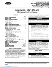
Carrier 48EJ Installation, Start-Up And Service Instructions Manual (119 pages)
Single Package Rooftop Units Electric Cooling/Gas Heating, with Reciprocating Compressor
Brand:
Carrier
| Category:
Air Conditioner
| Size: 6.67 MB
Table of Contents
Table of Contents
1
Safety Considerations
1
Step 1 - Provide Unit Support
1
Roof Curb
2
Alternate Unit Support
2
Installation
1
Roof Mount
2
Step 2 - Rig and Place Unit
2
Step 3 - Field Fabricate Ductwork
2
Step 4 - Make Unit Duct Connections
2
Base Unit Dimensions
7
Rigging Information
19
Rigging Weights
20
Physical Data
21
Operating Weights
26
CV Motor Weights
26
Vav Motor Weights
26
Air Distribution — Thru-The-Side
27
Air Distribution — Thru-The-Bottom
27
Evaporator Fan Motor Data
27
Combustion Fan Housing Location
28
Step 5 - Install Flue Hood
28
Step 6 - Trap Condensate Drain
28
Step 7 - Install Gas Piping
28
Field Gas Piping
29
48A,E Series Staged Gas Implementation
29
Step 8 - Controls Options
29
Constant Volume Applications
30
Controls Options and Configurations
30
Staged Gas Unit Applications
30
Thermistor Designations
30
Thermistors
30
Features with Thermostat Control of Unit
31
Supply-Air Thermistor Connections
31
Features with Sensor Control of Unit
32
Field Control Remote Start/Stop
32
Indoor Air Quality Sensor Configuration
32
Variable Air Volume (Vav) Applications
32
Features with Network Applications
33
Field Power Supply
33
When Installing Units
33
Step 9 - Make Electrical Connections
33
Power Wiring
33
Control Board Diagram
34
Electrical Data
35
Routing through Bottom of Unit
43
Routing through Side of Unit
43
Field Control Wiring
43
Field Power Wiring Connections
43
Control Box Diagram
44
Thermostat Wiring (CV Only)
45
Sensor Wiring (CV or VAV)
45
Heat Interlock Relay
45
Remote Field Control
45
Field Control Thermostat Wiring
47
Field Control Temperature Sensor Wiring (CV or VAV Units)
47
CCN Connection Approved Shielded Cables
47
Color Code Recommendations
47
Make Outdoor-Air Inlet Adjustments
48
Space Temperature Averaging Wiring
48
Field HIR (Heat Interlock Relay) Wiring
48
Economizer
48
Step 10 - Make Outdoor-Air Inlet
48
Adding Seal Strip to Top of Hood Sides
49
Economizer Hood Assembly
49
Adding Foam Strip to Cross Member
50
Adding Foam Strip to Hood Side
50
Adding Seal Strip to Back of Hood Top Mounting Flange
50
Adding Seal Strip to Sides of Hood Top Mounting Flange
50
Accessory Differential Enthalpy Control
51
Accessory Enthalpy Control
51
Economizer Settings
51
Enthalpy Control Installation
51
Differential Enthalpy Control and Sensor
52
Disable Economizer
52
Position Power Exhaust/Barometric Relief Damper Hood
52
Vav Building Pressure Transducer
52
Economizer Details
53
Psychrometric Chart for Enthalpy Control
53
Barometric Relief Damper and Power Exhaust Mounting Details
54
Pressure Transducer Locations
54
Step 12 - Install All Accessories
54
Motormaster III Control Baffle Details
55
Motormaster III Sensor Location
55
Install Motormaster III Controls
55
Electrical Connections
55
Ductwork
57
Side Supply and Return Units
57
Side Return Air Conversion
57
Step 13 - Field Modifications
57
Power Exhaust Relocated to Side Return Duct
58
Unit Preparation
58
Compressor Mounting
58
Start-Up
58
Crankcase Heaters
59
Variable Frequency Drive (VFD)
59
Carrier Default Program Parameter Values
60
Carrier VFD (Toshiba TOSVERT VF-S9) Program Parameter Values
62
Direct Digital Controls DIP Switch Configuration
63
Power Exhaust
63
DIP Switch Configuration
64
Condenser Fans and Motors
64
DIP Switch Factory Settings
65
Fan Performance
65
High Efficiency Motors
79
Air Quality Limits
79
Standard Efficiency Motors
79
Motor Limitations
79
Sequence of Operation
80
Return-Air Filters
80
Filter Replacement
80
Economizer Adjustment
80
User Defined Set Points
81
Software Control Link Points
81
Cooling, Variable Air Volume (Vav) Units
82
Gas Heating, Constant Volume (CV) Units
82
Heat Interlock Relay Wiring
83
Staged Gas Unit Heating
83
Gas Heating, Variable Air Volume (Vav) Units
83
Staged Gas System Components
84
Stage Gas System Inputs/Outputs
84
Operating Modes
84
Tempering (Cool) Mode
84
Navigator Display
85
Navigator Display Menu Structure
85
Morning Warm-Up
85
Space Temperature Reset Example
86
Occupied Heat and Morning Warm-Up Operation and Controlling Factors
86
Space Temperature Reset Sensor
86
Space Temperature Sensor Control
86
Field-Supplied Smoke Detector Wiring
87
Supply Air Temperature Reset
87
Power Exhaust Operation
87
Smoke Control Modes
87
Capacity Control, Cooling
88
Motormaster III Control
88
Head Pressure Control
88
Service Access
89
Cleaning
89
Main Burners
89
Service
89
Typical Gas Heating Section
90
Gas Heat Section Details
90
Evaporator Coil
90
Condensate Drain
90
Reassembling the Coupling into the Unit
91
Lubrication
91
Evaporator Fan Coupling Assembly
91
Evaporator Fan Performance Adjustment
91
Evaporator Fan Service and Replacement
92
Belt Tension Adjustment
92
Evaporator-Fan Motor Replacement
92
Condenser-Fan Adjustment
92
Thermostatic Expansion Valve (TXV)
93
Power Failure
93
Refrigerant Charge
93
Gas Valve Adjustment
93
Cooling Charging Chart
94
Gas Valve
94
Main Burner Removal
94
Replacement Parts
95
Relief Devices
95
Typical Wiring Schematics
95
Compressor Protection
95
Protective Devices
95
Filter Drier
95
Typical Power Schematic
96
Typical 48EK VAV 24-V Control Circuit
97
Typical CV 24-V Control Circuit
98
Typical 48EK VAV 115-V Control Circuit
99
Typical 48EJ CV 115-V Control Circuit
100
Label Diagram - Staged Gas Heat
101
Typical Refrigerant Circuiting
103
Troubleshooting
103
Typical Refrigerant Circuiting (48AJ,AK,AW,AY027,030)
104
Typical Refrigerant Circuiting (48AJ,AK,AW,AY035)
105
Typical Refrigerant Circuiting (48EJ,EK,EW,EY038,044)
106
Typical Refrigerant Circuiting (48AJ,AK,AW,AY040,050)
107
Typical Refrigerant Circuiting (48EJ,EK,EW,EY048)
108
Typical Refrigerant Circuiting (48EJ,EK,EW,EY054 and 058)
109
Typical Refrigerant Circuiting (48AJ,AK,AW,AY060)
110
Typical Refrigerant Circuiting (48EJ,EK,EW,EY064)
111
IGC Control (Heating and Cooling)
113
IGC Control Board LED Alarms
114
Diagnostic Leds
114
Control Board LED Alarms
114
I/O Channel Designations Base Module — CV
115
I/O Channel Designations Base Module — VAV
115
I/O Channel Designations Expansion Module (Field-Installed)
115
Service Training
116
Start-Up Checklist
117
Advertisement
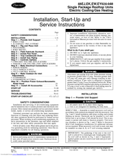
Carrier 48EJ Installation And Service Instructions Manual (65 pages)
Single Package Rooftop Units Electric Cooling/Gas Heating
Brand:
Carrier
| Category:
Gas Heater
| Size: 1.42 MB
Table of Contents
Table of Contents
1
Safety Considerations
1
Installation
1
Provide Unit Support
1
Step 2 - Rig and Place Unit
2
Alternate Unit Support
2
Roof Mount
2
Step 3 - Field Fabricate Ductwork
2
Roof Curb
3
Unit Leveling Tolerances Dimensions
4
VFD — Variable Frequency Drive
5
Base Unit Dimensions, 48EJ,EK024-034
5
Base Unit Dimensions, 48EW,EY024-034
7
Base Unit Dimensions, 48EW,EY038-048
8
Rigging Label
9
Physical Data
10
Evaporator Fan Motor Data
12
Air Distribution — Thru-The-Bottom
12
Air Distribution — Thru-The-Side
12
Step 4 - Install Flue Hood
12
Field Gas Piping
13
Step 5 — Trap Condensate Drain
13
Step 6 — Install Gas Piping
13
Step 7 — Controls Options
13
Controls Options and Configurations
14
Field Control Remote Start/Stop
15
Indoor Air Quality Sensor Configuration
15
Variable Air Volume (Vav) Applications
15
Field Power Supply
16
Power Wiring
16
Routing through Bottom of Unit
16
Step 8 - Make Electrical Connections
16
Control Board Diagram
17
Electrical Data
18
Field Control Wiring
21
Field Power Wiring Connections
21
Heat Interlock Relay
21
Sensor Wiring (CV or VAV)
21
Control Box Diagram (Sizes 038-048)
22
Field Control Temperature Sensor Wiring
22
Field Control Thermostat Wiring
22
Carrier Comfort Network Interface
23
CCN Connection Approved Shielded Cables
23
Remote Field Control
23
Space Temperature Averaging Wiring
23
Color Code Recommendations
24
Economizer
24
Economizer Hood Assembly
24
Make Outdoor-Air Inlet Adjustments
24
Step 9 - Make Outdoor-Air Inlet
24
Adding Seal Strip to Top of Hood Sides
25
Accessory Differential Enthalpy Control
26
Adding Foam Strip to Blockoff Baffle
26
Adding Foam Strip to Hood Side
26
Economizer Settings
26
Attaching Seal Strip to Filter Cover
27
Differential Enthalpy Control and Sensor
27
Differential Enthalpy Sensor Installation
27
Disable Economizer
27
Economizer Details
28
Psychrometric Chart for Enthalpy Control
28
Wiring Connections for Solid-State Enthalpy Control (HH57AC077)
28
Position Power Exhaust/Barometric Relief Damper Hood
29
Vav Building Pressure Transducer
29
Vav Duct Pressure Transducer
29
Electrical Connections
30
Install Field-Fabricated Wind Baffles
30
Pressure Transducer Locations
30
Step 11 — Install All Accessories
30
Adjustments
31
Crankcase Heaters
31
Refrigerant Service Ports
31
Variable Frequency Drive (VFD)
31
Power Exhaust
32
VFD Factory-Installed Jumpers
32
VFD Supply Air Pressure Set Point
32
Condenser Fans and Motors
33
Crankcase Heater
33
Evaporator Fan
33
Potentiometer Signal Levels
33
DIP Switch Configuration
34
DIP Switch Factory Settings
34
Power Exhaust Default Set Points
34
Available External Static Pressure
35
Fan Performance, 48EJ/EK024-034 — Vertical Discharge Units
35
Fan Performance, 48EJ,EK038,044 — Vertical Discharge Units
36
Fan Performance — Power Exhaust
38
High Efficiency Motors
38
Motor Limitations
38
Standard Efficiency Motors
38
Air Quantity Limits
39
Filter Replacement
39
Outdoor-Air Inlet Screens
39
Return-Air Filters
39
Cooling, Variable Volume Units
40
User Defined Set Points
40
Gas Heating, Constant Volume (CV) Units
41
Gas Heating, Variable Air Volume (Vav) Units
41
MORNING WARM-UP (VAV Only)
41
Heat Interlock Relay Wiring
42
Morning Warm-Up
42
Space Temperature Reset Sensor
42
Field-Supplied Smoke Detector Wiring
43
Power Exhaust Operation
43
Smoke Control Modes
43
Supply Air Temperature Reset
43
Start-Up
31
Time Guard Circuit
44
Head Pressure Control
44
Capacity Control, Cooling
44
Service
44
Combustion-Air Blower
45
Main Burners
45
Flue Gas Passageways
45
Lubrication
45
Evaporator Fan Service and Replacement
46
Belt Tension Adjustment
46
Typical Gas Heating Section
46
Gas Heat Section Details
46
Evaporator-Fan Motor Replacement
47
Condenser-Fan Adjustment
47
Power Failure
47
Gas Valve Adjustment
47
Overtemperature
48
Overcurrent
48
Compressor Protection
48
Main Burner Removal
48
Evaporator Fan Motor Protection
49
Condenser-Fan Motor Protection
49
High- and Low-Pressure Switches
49
Compressor Lockout Logic
49
Typical Wiring Schematics
50
Typical VAV 115-V Control Circuit
52
Typical CV 115-V Control Circuit
53
Typical VAV 24-V Control Circuit
54
Typical CV 24-V Control Circuit
55
Typical Refrigerant Circuiting
56
Troubleshooting
56
Typical Refrigerant Circuiting (48EJ,EK,EW,EY038,044)
57
Igc Control Scheme (Heating and Cooling)
59
Alarm Codes for the Igc Control Board
60
IGC Control Board LED Alarms
60
Control Board LED Alarms
60
Diagnostic Leds
60
I/O Channel Designations Base Module — CV
61
I/O Channel Designations Base Module — VAV
61
I/O Channel Designations Expansion Module (Field-Installed)
61
Packaged Service Training
62
Pre-Start-Up
63
Start-Up Checklist
63
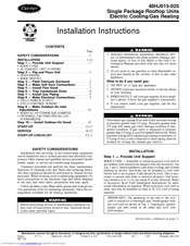
Carrier 48EJ User Manual (32 pages)
Single Package Rooftop Units Electric Cooling/Gas Heating
Brand:
Carrier
| Category:
Heating System
| Size: 0.69 MB
Table of Contents
Table of Contents
1
Installation Instructions
1
Installation
2
Step 2 - Rig and Place Unit
3
Roof Mount
3
Positioning
3
Step 4 - Make Unit Duct Connections
7
Step 5 - Install Flue Hood
7
Step 6 — Trap Condensate Drain
8
Step 7 — Install Gas Piping
8
Step 8 - Make Electrical Connections
9
Field Power Supply
9
Step 9 - Make Outdoor-Air Inlet
10
Adjustments
10
Optional Factory-Installed Economizer
10
Step 10 - Install Outdoor-Air Hood
10
Start-Up
12
Service
18
Start-Up Checklist
32
Advertisement
Advertisement
Related Products
Carrier 48ES
Carrier 48ES42A
Carrier 48ES48A
Carrier 48EM006
Carrier Comfort 48EZ-A2404030
Carrier Comfort 48EZ-NA2404030
Carrier Comfort 48EZ-NA3006030
Carrier Comfort 48EZ-NA3604030
Carrier Comfort 48EZ-NA3604050
Carrier Comfort 48EZ-A3606050
Carrier Categories
Air Conditioner
Heat Pump
Furnace
Thermostat
Chiller
More Carrier Manuals
Login
Sign In
OR
Sign in with Facebook
Sign in with Google
Upload manual
Upload from disk
Upload from URL