Sign In
Upload
Manuals
Brands
Carrier Manuals
Chiller
17EX Series
Carrier 17EX Series Manuals
Manuals and User Guides for Carrier 17EX Series. We have
3
Carrier 17EX Series manuals available for free PDF download: Start-Up, Operation And Maintenance Instructions Manual, Start Up & Operation Manual
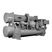
Carrier 17EX Series Start-Up, Operation And Maintenance Instructions Manual (437 pages)
50/60 Hz Centrifugal Liquid Chillers with HFC-134a
Brand:
Carrier
| Category:
Chiller
| Size: 6.9 MB
Table of Contents
Safety Considerations
1
Table of Contents
7
Motor-Compressor
18
17/19EX Machine Familiarization
39
Machine Identification Label
39
System Components
39
Motor Starter
41
Pic System Components
52
Pic System Functions
74
Safety Controls
79
Default Screen Freeze
81
Ramp Loading Control
82
High Discharge Temperature Control
84
Oil Sump Temperature Control
85
Oil Cooler
86
Spare Safety Inputs
87
Condenser Pump Control
88
Condenser Freeze Prevention
88
Surge Prevention Algorithm
93
Surge Protection
95
Ice Build Control
104
Attach to Network Device Control
109
Service Operation
111
Shutdown Sequence
120
Automatic Soft Stop Amps Threshold
121
Chilled Water Recycle Mode
122
Safety Shutdown
124
Open Oil Circuit Valves
129
Standing Vacuum Test
134
Inspect Water Piping
137
Carrier Comfort Network Interface
145
Oil Charge
150
Input the Design Set Points
152
Input Service Configurations
153
Manual Operation of the Guide Vanes
167
Operating Instructions
180
Check the Running System
181
After Limited Shutdown
184
Extended Shutdown
184
After Extended Shutdown
184
Cold Weather Operation
185
Manual Guide Vane Operation
185
Refrigeration Log
186
General Maintenance
195
Refrigerant Leak Testing
197
Leak Rate
197
Weekly Maintenance
221
Check the Lubrication System
221
Scheduled Maintenance
223
Changing Oil Filter
224
Oil Specification
226
Oil Changes
226
Refrigerant Filter
227
Oil Reclaim Filter
228
Inspect Refrigerant Float System
228
Inspect Relief Valves and Piping
228
Inspect the Heat Exchanger Tubes
246
Troubleshooting Guide
254
Control Algorithms Checkout Procedure
263
Notes on Module Operation
270
Replacing Defective Processor Modules
275
Advertisement
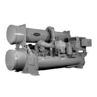
Carrier 17EX Series Start Up & Operation Manual (116 pages)
Centrifugal Liquid Chillers 50/60 Hz with HFC-134a
Brand:
Carrier
| Category:
Chiller
| Size: 2.6 MB
Table of Contents
Safety Considerations
1
Table of Contents
2
Cooler
8
Condenser
8
Motor-Compressor
8
Control Center
8
Motor Starter
8
Utility Vessel
8
Refrigeration Cycle
8
Motor/Oil Refrigeration Cooling Cycle (19Ex Chillers)
8
Cycle
10
Details
10
Open-Drive Machines (17 Series Lubrication Cycle
12
Cycle
12
Summary
12
Details
12
Starters
12
Controls
12
Definitions
12
General
12
PIC System Components
14
Processor Module (Psio)
14
Starter Management Module (Smm)
14
Local Interface Device (Lid)
14
6-Pack Relay Board
14
8-Input Modules
14
Oil Heater Contactor (1C)
14
Oil Pump Contactor (2C)
14
HOT GAS BYPASS CONTACTOR RELAY (3C) (Optional)
14
Oil Auxiliary Relay (4C)
14
Oil Auxiliary Relay (4C
20
LID Operation and Menus
21
General
21
Alarms and Alerts
21
Lid Default Screen Menu Items
22
Menu Structure
22
To View or Change Point Status
22
Menu Structure
23
Override Operations
25
To View or Change Time Schedule Operation
25
To View and Change Set Points
26
Service Operation
26
PIC System Functions
35
Capacity Control
35
Entering Chilled Water Control
35
Proportional Bands and Gain
35
Demand Limiting
35
Machine Timers
35
Occupancy Schedule
35
Safety Controls
35
Shunt Trip
36
Default Screen Freeze
36
Motor Cooling Control (Hermetic Motors Only)
36
Auxiliary Oil Pump Control (Open-Drive Machines Only)
36
Shaft Seal Oil (Open Drive Machines Only)
36
Ramp Loading Control
36
Capacity Override
36
High Discharge Temperature Control
36
Oil Sump Temperature Control
38
Oil Cooler
38
Remote Start/Stop Controls
38
Spare Safety Inputs
38
Spare Alarm Contacts
38
Condenser Pump Control
39
Condenser Freeze Prevention
39
Tower-Fan Relay
39
Auto. Restart after Power Failure
39
Water/Brine Reset
39
Demand Limit Control Option
40
Surge Prevention Algorithm
40
Surge Protection
40
Lead/Lag Control
40
Common Point Sensor Installation
41
Machine Communication Wiring
41
Lead/Lag Operation
41
Load Balancing
41
Faulted Chiller Operation
42
Load Balancing
42
Auto. Restart after Power Failure
42
Ice Build Control
42
Ice Build Initiation
42
Termination of Ice Build
42
Start-Up/Recycle Operation
43
Temperature Control During Ice Build
43
Termination of Ice Build
43
Return to Non-Ice Build Operations
43
Attach to Network Device Control
43
Attaching to Other Ccn Modules
43
Service Operation
44
To Log on
44
To Log off
44
Holiday Scheduling
44
Start-Up/Shutdown/Recycle Sequence
45
Local Start-Up
45
Shutdown Sequence
46
Automatic Soft Stop Amps Threshold
46
Chilled Water Recycle Mode
46
Safety Shutdown
46
Before Initial Start-Up
47
Job Data Required
47
Equipment Required
47
Using the Utility Vessel and Pumpout System
47
Remove Shipping Packaging
47
Open-Drive Motor Electrical Connection
47
Open-Drive Motor Auxiliary Devices
48
Open Oil Circuit Valves
48
Tighten All Gasketed Joints and Guide Vane Shaft Packing
48
Check Machine Tightness
48
Refrigerant Tracer
48
Leak Test Machine
48
Standing Vacuum Test
49
Machine Dehydration
51
Inspect Water Piping
52
Check Optional Pumpout Compressor Water Piping
52
Check Relief Devices
52
Inspect Wiring
52
Check Insulation Resistance
52
Carrier Comfort Network Interface
53
Check Starter
54
Oil Charge
54
Power up the Controls and Check the Oil Heater
54
Software Version
54
Set up Machine Control Configuration
55
Input the Design Set Points
55
Input Service Configurations
55
Password
55
Input Time and Date
55
Change Lid Configuration if Necessary
55
Modify Controller Identification if
55
Input Equipment Service Parameters if
55
Necessary
56
Modify Equipment Configuration if
56
Check Voltage Supply
56
Perform an Automated Control Test
56
Check Pumpout System Controls and Optional Pumpout Compressor
57
High Altitude Locations
57
Charge Refrigerant into Machine
57
Initial Start-Up
58
Manual Operation of the Guide Vanes
58
Dry Run to Test Start-Up Sequence
58
Check Rotation (Open-Drive Motor)
58
Open Drive Motor Initial Start-Up
58
Check Rotation (Hermetic Motor)
59
Check Oil Pressure and Compressor Stop
59
Calibrate Motor Current Demand Setting
60
To Prevent Accidental Start-Up
60
Hot Alignment Check for Open-Drive Machines
60
Doweling for Open-Drive Machines
60
Check Machine Operating Condition
60
Instruct the Customer Operator
60
Cooler-Condenser
60
Utility Vessel
60
Pumpout System
60
Motor Compressor Assembly
60
Operating Instructions
61
Initial Start-Up
61
Prepare the Machine for Start-Up
61
To Start the Machine
61
Check the Running System
61
To Stop the Machine
61
After Limited Shutdown
61
Extended Shutdown
62
After Extended Shutdown
62
Cold Weather Operation
62
Manual Guide Vane Operation
62
Refrigeration Log
62
Procedures
64
Operating the Optional Pumpout Compressor
64
To Read Refrigerant Pressures
64
Transferring Refrigerant from Normal Operation into the Utility Vessel
66
Transferring Refrigerant from Normal Operation into the Cooler/Condenser/Compressor Section
66
Return Refrigerant to Normal Operating Conditions
66
General Maintenance
67
Procedures
67
Refrigerant Properties
67
Adding Refrigerant
67
Removing Refrigerant
67
Refrigerant Leak Testing
67
Leak Rate
67
Test after Service, Repair, or Major Leak
67
Repair the Leak, Retest, and Apply Standing Vacuum Test
67
Checking Guide Vane Linkage
67
Contact Seal Maintenance (Open-Drive Machines)
68
Seal Disassembly
68
Seal Reassembly
68
Machine Alignment (Open-Drive Machines)
70
Alignment Methods
70
Preliminary Alignment
70
Near Final Alignment
70
Hot Alignment Check
70
Preliminary Alignment
71
Near Final Alignment
71
Near Final Alignment
74
Hot Alignment Check
74
Scheduled Maintenance
76
Service Ontime
76
Inspect the Control Center
76
Check Safety and Operating Controls Monthly
76
Changing Oil Filter
76
19Ex Compressors
76
Fa Style Compressors
76
Oil Specification
77
Oil Changes
77
Refrigerant Filter
77
Oil Reclaim Filter
77
Inspect Refrigerant Float System
77
Inspect Relief Valves and Piping
77
Coupling Maintenance (Open-Drive Machines)
77
Procedure
77
Motor Maintenance (Open-Drive Machines)
78
Cleanliness
78
Sleeve Bearings
79
Open-Drive Motor Handling/Rigging
81
Open-Drive Motor Storage
81
Compressor Bearing and Gear Maintenance
81
Inspect the Heat Exchanger Tubes
81
Cooler
81
Water Leaks
82
Water Treatment
82
Inspect the Starting Equipment
82
Check Pressure Transducers
82
Pumpout System Maintenance
82
Optional Pumpout Compressor Oil Charge
82
Pumpout Safety Control Settings
83
Ordering Replacement Chiller Parts
83
Open-Drive Motor Renewal Parts
83
Troubleshooting Guide
83
Overview
83
Checking the Display Messages
83
Checking Temperature Sensors
83
Resistance Check
83
Voltage Drop
83
Check Sensor Accuracy
84
Dual Temperature Sensors
84
Checking Pressure Transducers
84
Oil Differential Pressure/Power Supply
84
Troubleshooting Transducers
85
Transducer Replacement
85
Control Algorithms Checkout Procedure
85
Control Test
85
Troubleshooting Guide
86
Control Modules
95
Notes on Module Operation
95
Processor Module (PSIO)
95
Inputs
95
Outputs
95
Starter Management Module (SMM)
96
Options Modules (8-Input)
96
Replacing Defective Processor Modules
96
Installation of New Psio Module
97
17/19Ex Physical Data and Wiring Schematics
97
Compressor Fits and Clearances
102
Index
115
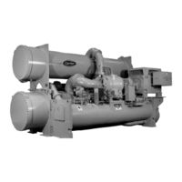
Carrier 17EX Series Start-Up, Operation And Maintenance Instructions Manual (120 pages)
Externally Geared Centrifugal Liquid Chillers
Brand:
Carrier
| Category:
Chiller
| Size: 1.96 MB
Table of Contents
Safety Considerations
1
Table of Contents
2
Introduction
5
Abbreviations
5
17Ex Chiller Familiarization
5
Chiller Identification Label
5
System Components
5
Cooler
5
Condenser
5
Compressor
5
Control Center
5
Motor Starter (Purchased Separately)
5
Oil Cooling Cycle
8
Compressor Oil Cooling
8
External Gear Oil Cooling
8
Lubrication Cycle
8
Compressor Lubrication Cycle
8
External Gear Lubrication Cycle
9
Starters
9
Controls
11
Definitions
11
Analog Signal
11
Digital Signal
11
Volatile Memory
11
General
11
PIC System Components
12
Processor/Sensor Input/Output Module (Psio)
12
Starter Management Module (Smm)
12
Local Interface Device (Lid)
12
Six-Pack Relay Board
16
Four-In/Two-Out (4-In/2-Out) Module
16
Oil Heater Contactor (1C)
16
Compressor Oil Pump Contactor (2C) and Gear
16
Oil Pump Contactor (5C)
16
HOT GAS BYPASS CONTACTOR RELAY (3C) (Optional)
16
Oil Auxiliary Relay (4C)
16
Control Transformers (T1-T4)
16
Control and Oil Heater Voltage
16
Oil Differential Pressure/Power Supply
16
Lid Default Screen Menu Items
17
Menu Structure
17
To View or Change Point Status
17
Override Operations
18
To View or Change Time Schedule Operation
18
To View and Change Set Points
22
Service Operation
22
PIC System Functions
32
Capacity Control
32
Entering Chilled Water Control
32
Deadband
32
Proportional Bands and Gain
32
Demand Limiting
32
Chiller Timers
32
Occupancy Schedule
32
Safety Controls
33
Shunt Trip
33
Default Screen Freeze
33
Auxiliary Compressor Oil Pump Control
33
Auxiliary Gear Oil Pump Control
33
Shaft Seal Oil Control
33
Ramp Loading Control
33
Capacity Override
35
High Discharge Temperature Control
35
Oil Sump Temperature Control
35
Oil Cooler
36
Remote Start/Stop Controls
36
Spare Safety Inputs
36
Spare Alarm Contacts
36
Condenser Pump Control
36
Condenser Freeze Prevention
36
Tower-Fan Relay
36
Auto. Restart after Power Failure
36
Water/Brine Reset
37
Demand Limit Control Option
37
8-Input Module)
37
Surge Prevention Algorithm
37
Surge Protection
38
Lead/Lag Control
38
Common Point Sensor Installation
38
Chiller Communication Wiring
38
Lead/Lag Operation
39
Faulted Chiller Operation
40
Load Balancing
40
Auto. Restart after Power Failure
40
Ice Build Control
40
Ice Build Initiation
40
Start-Up/Recycle Operation
40
Temperature Control During Ice Build
41
Termination of Ice Build
41
Return to Non-Ice Build Operations
41
Attach to Network Device Control
41
Attaching to Other Ccn Modules
41
Service Operation
42
To Access the Service Screens
42
To Log off
42
Holiday Scheduling
42
Controls
43
Start-Up/Shutdown/Recycle Sequence
43
Local Start-Up
43
Shutdown Sequence
44
Automatic Soft Stop Amps Threshold
44
Chilled Water Recycle Mode
44
Safety Shutdown
45
Before Initial Start-Up
45
Job Data Required
45
Equipment Required
45
Using the Economizer/Storage Vessel and Pumpout System
45
Remove Shipping Packaging
45
Motor
45
External Gear
45
Motor Electrical Connection
45
Motor Auxiliary Devices
46
Open Oil Circuit Valves
46
Tighten All Gasketed Joints and Guide Vane Shaft Packing
46
Check Chiller Tightness
46
Refrigerant Tracer
46
Leak Test the Chiller
46
Standing Vacuum Test
49
Chiller Dehydration
49
Inspect Water Piping
50
Check Optional Pumpout Compressor Water Piping
50
Check Relief Devices
50
Inspect Wiring
50
Check Insulation Resistance
50
Motor Pre-Start Checks
51
External Gear Pre-Start Checks
51
Carrier Comfort Network Interface
53
Check Starter
53
Power up the Controls and Check the Compressor Oil Heater
54
Compressor Oil Charge
54
Set up Chiller Control Configuration
54
Input the Design Set Points
54
Input Service Configurations
54
Password
54
Input Time and Date
54
Check Pumpout System Controls and Optional Pumpout Compressor
56
Initial Start-Up
57
High Altitude Locations
57
Charge Refrigerant into Chiller
57
Manual Operation of the Guide Vanes
58
Dry Run to Test Start-Up Sequence
58
Check Motor Rotation
58
Initial Motor Start-Up
58
Disc Coupling Installation and Alignment
59
Check Oil Pressure and Compressor Stop
61
Calibrate Motor Current Demand Setting
61
To Prevent Accidental Start-Up
61
Hot Alignment Check
61
Doweling
61
Check Chiller Operating Condition
61
Start-Up/Shutdown/Recycle Sequence
62
Instruct the Operator
62
Operating Instructions
62
Prepare the Chiller for Start-Up
62
Starting the Chiller
62
Check the Running System
62
Stopping the Chiller
62
Initial Start-Up
62
Operating the Optional Pumpout Compressor
63
Procedures
63
Reading Refrigerant Pressures
63
Transferring Refrigerant into the Economizer/Storage Vessel
66
Procedures
67
Return Chiller to Normal Operating Conditions
67
Transferring Refrigerant into the Cooler/Condenser/Compressor Section
67
After Limited Shutdown
63
Extended Shutdown
63
After Extended Shutdown
63
Cold Weather Operation
63
Manual Guide Vane Operation
63
Refrigeration Log
63
General Maintenance
67
Refrigerant Properties
67
Adding Refrigerant
67
Removing Refrigerant
67
Adjusting the Refrigerant Charge
67
Refrigerant Leak Testing
67
Leak Rate
67
Repair the Leak, Retest, and Apply Standing Vacuum Test
68
Checking Guide Vane Linkage
68
Contact Seal Maintenance
68
Seal Disassembly
68
Chiller Alignment
71
Alignment Methods
71
Preliminary Alignment
71
Near Final Alignment
71
Hot Alignment Check
71
Weekly Maintenance
76
Check the Lubrication System
76
Scheduled Maintenance
76
Service Ontime
76
Inspect the Control Center
76
Check Safety and Operating Controls Monthly
76
Changing the Oil Filters
76
Compressor Oil Filter
76
Oil Specifications
77
Oil Changes
77
Inspect Relief Valves and Piping
78
Coupling Maintenance
78
Motor Maintenance
78
Motor Handling/Rigging
81
Motor Storage
81
External Gear Storage
81
SHORT-TERM STORAGE (Indoors
81
LONG-TERM STORAGE (Indoors
81
Extended Downtime
82
Compressor Bearing Maintenance
82
External Gear Maintenance
82
Inspect the Heat Exchanger Tubes
82
Water Leaks
82
Water Treatment
82
Inspect the Starting Equipment
83
Check Pressure Transducers
83
Pumpout System Maintenance
83
Optional Pumpout Compressor Oil Charge
83
Pumpout Safety Control Settings
83
Ordering Replacement Chiller Parts
83
Motor Replacement Parts
83
External Gear Replacement Parts
83
Troubleshooting Guide
83
Overview
83
Checking the Display Messages
84
Checking Temperature Sensors
84
Checking Pressure Transducers
84
Oil Differential Pressure/Power Supply
85
Control Algorithms Checkout Procedure
85
Control Test
85
Troubleshooting Guide
86
Control Modules
96
RED Leds
96
Notes on Module Operation
96
Processor/Sensor Input/Output Module (PSIO)
97
Starter Management Module (SMM)
97
Inputs
97
Outputs
97
Options Modules (8-Input)
98
Four-In/Two-Out Module
98
Replacing Defective Processor Modules
98
Installation of New Psio Module
98
Physical Data and Wiring Schematics
99
Index
115
Advertisement
Advertisement
Related Products
Carrier 17EA
Carrier 17/19EX
Carrier OPEN-DRIVE CENTRIFUGAL LIQUID CHILLERS 17CB
Carrier 17CB1300
Carrier 17CB1400
Carrier 17CB2000
Carrier 17P
Carrier 17S
Carrier 17MA
Carrier 17PA
Carrier Categories
Air Conditioner
Heat Pump
Furnace
Thermostat
Chiller
More Carrier Manuals
Login
Sign In
OR
Sign in with Facebook
Sign in with Google
Upload manual
Upload from disk
Upload from URL