Sign In
Upload
Manuals
Brands
Canon Manuals
Printer
iPF750 series
Canon iPF750 series Manuals
Manuals and User Guides for Canon iPF750 series. We have
3
Canon iPF750 series manuals available for free PDF download: Service Manual
Canon iPF750 series Service Manual (328 pages)
A4- to A0-size
Brand:
Canon
| Category:
Printer
| Size: 7.17 MB
Table of Contents
Table of Contents
7
Service Manual
1
Symbols Used
4
Chapter 1 PRODUCT DESCRIPTION
11
Table of Contents
13
Product Overview
15
Features
16
Cutter
17
Ink Tank
17
Printhead
17
Roll Holder
17
Stand (ST-33)
19
Stand (ST-34)
21
Consumables
24
Hard Disk Drive
24
Ink Tank
24
Product Specifications
25
Product Specifications
26
Detailed Specifications
31
Interface Specifications
31
Names and Functions of Components
33
Front
33
Side
34
Top Cover (Inside)
35
Carriage
36
Roll Unit Cover (Inside)
36
Ink Tank Cover (Inside)
37
Stand (ST-33)
38
Stand (ST-34)
39
Basic Operation
40
Operation Panel
40
Display
41
Menu
42
Menu
60
Safety and Precautions
78
Moving Parts
78
Safety Precautions
78
Adhesion of Ink
79
Electric Parts
80
Other Precautions
82
Printhead
82
Handling the Printer
83
Ink Tank
83
Precautions against Static Electricity
83
Confirming the Firmware Version
85
Notes on the Data Stored in the Printer
85
Precautions against Static Electricity
85
Precautions for Disassembly/Reassembly
85
Precautions When Servicing Printer
85
Self-Diagnostic Feature
85
Disposing of the Lithium Battery
86
Chapter 2 TECHNICAL REFERENCE
87
Table of Contents
89
Basic Operation Outline
91
Printer Diagram
91
Printer Diagram
92
Print Signal Sequence
93
Print Driving
94
Firmware
96
Operation Sequence at Power-On
96
Operation Sequence at Power-Off
97
Print Control
98
Head Management
104
Pause between
104
Print Position Adjustment Function
104
Printhead Overheating Protection Control
104
Sleep Mode
104
White Raster Skip
104
Hard Disk Drive
105
Printer Mechanical System
106
Outline
106
Ink Passage
107
Overview of Ink Passage
107
Ink Tank Unit
108
Structure of Ink Tank Unit
108
Carriage Unit
110
Functions of Carriage Unit
110
Structure of Carriage Unit
111
Printhead
114
Structure of Printhead
114
Functions of Purge Unit
115
Purge Unit
115
Structure of Purge Unit
118
Maintenance Cartridge
120
Air Flow
121
Outline
123
Overview of Paper Path
123
Paper Path
123
Paper Path
124
Structure of Feed Roller Unit
124
Cutter Unit
126
Structure of Cutter Unit
126
Printer Electrical System
127
Outline
127
Overview
127
Overview
129
Main Controller
131
Main Controller PCB Components
131
Main Controller PCB Components
132
HDD Expansion PCB Components
133
Carriage PCB Components
134
Carriage Relay PCB
134
Maintenance Cartridge Relay PCB
134
Maintenance Cartridge Relay PCB Components
134
Power Supply
135
Power Supply Block Diagram
135
Detection Functions with Sensors
136
Covers
136
Ink Passage System
137
Carriage System
140
Paper Path System
142
Others
144
Chapter 3 INSTALLATION
145
Transporting the Printer
149
Reinstalling the Printer
151
Chapter 4 DISASSEMBLY/REASSEMBLY
153
Disassembly/Reassembly
153
Table of Contents
155
Service Parts
157
Disassembly/Reassembly
158
Points to Note on Disassembly and Reassembly
158
Moving the Carriage Manually
158
Note: Items that Should Never be Disassembled
158
Units Requiring Draining of Ink
159
External Covers
160
Drive Unit
169
Cutter
172
Carriage Unit
174
Purge Unit
181
Purge Unit
182
Ink Tank Unit
188
Ink Tube Unit
192
Waste Ink Collection Unit
196
Multi Sensor
201
Linear Encoder
202
Head Management Sensor
207
Pcbs
208
Opening the Cap/Moving the Wiper Unit
209
Opening/Closing the Ink Supply Valve/Subtank Air Passage Valve
211
Draining the Ink
212
Applying the Grease
213
Adjustment and Setup Items
217
Adjustment Item List
217
Procedure after Replacing the Carriage Unit or Multi Sensor
217
Procedure after Replacing the Feed Roller or Feed Roller Encoder
217
Procedure after Replacing the Head Management Sensor
217
Chapter 5 MAINTENANCE
219
Consumable Parts
223
Periodic Replacement Parts
223
Periodic Maintenance
224
Chapter 6 TROUBLESHOOTING
229
Troubleshooting
229
Table of Contents
231
Location of Connectors and Pin Arrangement
233
Troubleshooting
233
Main Controller PCB
233
Carriage PCB
238
Carriage PCB
240
Power Supply
244
Version up
245
Firmware Update Tool
245
Service Tools
249
Tool List
249
Outline
233
Outline of Troubleshooting
233
Service Mode/Special Mode
253
Service Mode
255
Service Mode Operation
255
Map of the Service Mode
256
Details of Service Mode
263
E-Maintenance/Imageware Remote
278
E-Maintenance/Imageware Remote
279
Viewing PRINT INF
289
Special Mode
304
Special Modes for Servicing
304
Outline
311
Warning Table
312
Warnings
312
Error Table
315
Errors
315
Sevice Call Table
326
Service Call Errors
326
Advertisement
Canon iPF750 series Service Manual (326 pages)
Brand:
Canon
| Category:
Plotter
| Size: 30.04 MB
Table of Contents
Table of Contents
5
Chapter 1 PRODUCT DESCRIPTION
9
Product Overview
11
Features
12
Ink Tank
12
Printhead
12
Cutter
13
Roll Holder
13
Stand (ST-34)
14
Consumables
17
Hard Disk Drive
17
Product Specifications
18
Detailed Specifications
19
Interface Specifications
19
Names and Functions of Components
21
Front
21
Side
22
Top Cover (Inside)
23
Carriage
24
Roll Unit Cover (Inside)
24
Ink Tank Cover (Inside)
25
Stand (ST-34)
26
Basic Operation
27
Operation Panel
27
Display
28
Menu
29
Safety and Precautions
49
Moving Parts
49
Safety Precautions
49
Adhesion of Ink
50
Electric Parts
51
Other Precautions
52
Printhead
52
Handling the Printer
53
Ink Tank
53
Confirming the Firmware Version
55
Notes on the Data Stored in the Printer
55
Precautions against Static Electricity
55
Precautions for Disassembly/Reassembly
55
Precautions When Servicing Printer
55
Self-Diagnostic Feature
55
Disposing of the Lithium Battery
56
Chapter 2 TECHNICAL REFERENCE
57
Chapter 2 Technical Reference
58
Basic Operation Outline
60
Printer Diagram
60
Print Signal Sequence
61
Print Driving
62
Firmware
64
Operation Sequence at Power-On
64
Operation Sequence at Power-Off
65
Head Management
66
Pause between
66
Print Position Adjustment Function
66
Printhead Overheating Protection Control
66
Shut down Mode
66
Sleep Mode
66
White Raster Skip
66
Hard Disk Drive
67
Printer Mechanical System
68
Outline
68
Ink Passage
69
Overview of Ink Passage
69
Ink Tank Unit
70
Structure of Ink Tank Unit
70
Carriage Unit
72
Functions of Carriage Unit
72
Structure of Carriage Unit
73
Printhead
76
Structure of Printhead
76
Functions of Purge Unit
77
Purge Unit
77
Structure of Purge Unit
80
Maintenance Cartridge
82
Air Flow
83
Outline
85
Overview of Paper Path
85
Paper Path
85
Paper Path
86
Structure of Feed Roller Unit
86
Cutter Unit
88
Structure of Cutter Unit
88
Printer Electrical System
89
Outline
89
Overview
89
Main Controller
91
Main Controller PCB Components
91
Connectors and Pin Arrangement of Main Controller PCB
93
Carriage PCB Components
100
Carriage Relay PCB
100
HDD Expansion PCB Components
100
Connectors and Pin Arrangement of Carriage PCB
101
Maintenance Cartridge Relay PCB
105
Maintenance Cartridge Relay PCB Components
105
Power Supply
106
Power Supply Block Diagram
106
Connectors and Pin Arrangement of Power Supply PCB
107
Detection Functions with Sensors
108
Covers
108
Ink Passage System
109
Carriage System
112
Paper Path System
114
Others
116
Chapter 3 INSTALLATION
117
Transporting the Printer
118
Transporting the Printer
119
Reinstalling the Printer
124
Chapter 4 Disassembly/Reassembly
126
Service Parts
127
Disassembly/Reassembly
128
Points to Note on Disassembly and Reassembly
128
Moving the Carriage Manually
128
Note: Items that Should Never be Disassembled
128
Units Requiring Draining of Ink
129
External Covers
130
Drive Unit
141
Cutter
145
Purge Unit
147
Ink Tank Unit
151
Ink Tube Unit
155
Waste Ink Collection Unit
159
Multi Sensor
164
Linear Encoder
165
Head Management Sensor
170
Pcbs
171
Opening/Closing the Ink Supply Valve
172
Draining the Ink
173
Applying the Grease
174
Adjustment and Setup Items
178
Adjustment Item List
178
Procedure after Replacing the Carriage Unit or Multi Sensor
178
Procedure after Replacing the Feed Roller or Feed Roller Encoder
178
Procedure after Replacing the Head Management Sensor
178
Chapter 5 MAINTENANCE
179
Periodic Replacement Parts
181
Consumable Parts
181
Periodic Maintenance
183
Chapter 6 TROUBLESHOOTING
186
Troubleshooting
186
Chapter 6 Troubleshooting
187
Error Code
188
Troubleshooting
188
Warning Table
189
Warnings
189
Error Table
193
Errors
193
Service Call Errors
204
Sevice Call Table
204
Outline
188
Outline of Troubleshooting
188
Service Software
205
L Printer Service Tool
205
Firmware Update Tool
209
Imageprograf Firmware Update Tool
209
Service Tools
211
Tool List
211
Chapter 7 SERVICE MODE
212
Service Mode
212
Chapter 7 Service Mode
213
Service Mode
214
Service Mode Operation
214
Map of the Service Mode
215
Details of Service Mode
223
E-Maintenance/Imageware Remote
241
Viewing PRINT INF
251
Special Mode
266
Special Modes for Servicing
266
Table of Contents
269
Stand Unit St-33
276
Printer & Accessories
277
Covers
280
Roll Unit
283
Electrical Part
286
Ink Supply & Purge Unit
288
Linear Scale
293
Carriage Unit
294
Air Flow Fan Unit
297
Cutter Unit
299
Platen & Guide Unit
301
Pinch Roller Unit
303
Feed Roller Unit
304
Tool
306
Canon iPF750 series Service Manual (272 pages)
Brand:
Canon
| Category:
Plotter
| Size: 7.78 MB
Table of Contents
Table of Contents
7
Chapter 1 PRODUCT DESCRIPTION
11
Table of Contents
13
Product Overview
15
Features
16
Ink Tank
16
Printhead
16
Cutter
17
Roll Holder
17
Stand
19
Consumables
21
Hard Disk Drive
21
Product Specifications
22
Product Specifications
23
Detailed Specifications
25
Interface Specifications
25
Names and Functions of Components
26
Front
26
Side
27
Top Cover (Inside)
27
Carriage
28
Roll Unit Cover (Inside)
28
Ink Tank Cover (Inside)
29
Ink Tank Cover (Inside)
30
Stand
30
Basic Operation
32
Operation Panel
32
Display
33
Menu
34
Safety and Precautions
52
Adhesion of Ink
52
Moving Parts
52
Safety Precautions
52
Electric Parts
54
Other Precautions
56
Printhead
56
Handling the Printer
57
Ink Tank
57
Confirming the Firmware Version
59
Disposing of the Lithium Battery
59
Notes on the Data Stored in the Printer
59
Precautions against Static Electricity
59
Precautions for Disassembly/Reassembly
59
Precautions When Servicing Printer
59
Self-Diagnostic Feature
59
Chapter 2 TECHNICAL REFERENCE
63
Table of Contents
65
Basic Operation Outline
67
Printer Diagram
67
Printer Diagram
68
Print Signal Sequence
69
Print Driving
70
Firmware
72
Operation Sequence at Power-On
72
Operation Sequence at Power-Off
73
Print Control
74
Hard Disk Drive
80
Head Management
80
Pause between
80
Print Position Adjustment Function
80
Printhead Overheating Protection Control
80
Sleep Mode
80
White Raster Skip
80
Printer Mechanical System
82
Outline
82
Ink Passage
83
Overview of Ink Passage
83
Ink Tank Unit
84
Structure of Ink Tank Unit
84
Carriage Unit
86
Functions of Carriage Unit
86
Structure of Carriage Unit
87
Printhead
90
Structure of Printhead
90
Functions of Purge Unit
91
Purge Unit
91
Structure of Purge Unit
94
Maintenance Cartridge
96
Air Flow
97
Outline
99
Overview of Paper Path
99
Paper Path
99
Paper Path
100
Structure of Feed Roller Unit
100
Cutter Unit
102
Structure of Cutter Unit
102
Printer Electrical System
103
Outline
103
Overview
103
Overview
105
Main Controller
107
Main Controller PCB Components
107
HDD Expansion PCB Components
109
Carriage PCB Components
110
Carriage Relay PCB
110
Maintenance Cartridge Relay PCB
110
Maintenance Cartridge Relay PCB Components
110
Power Supply
111
Power Supply Block Diagram
111
Detection Functions with Sensors
112
Sensors for Covers
112
Ink Passage System
113
Carriage System
116
Paper Path System
118
Others
120
Chapter 3 INSTALLATION
121
Transporting the Printer
125
Reinstalling the Printer
127
Service Parts/Applying the Grease
131
Service Parts
133
Chapter 4 DISASSEMBLY/REASSEMBLY
134
Points to Note on Disassembly and Reassembly
134
External Covers
135
Drive Unit
144
Cutter
147
Cutter
148
Carriage Unit
149
Purge Unit
156
Purge Unit
157
Ink Tank Unit
158
Ink Tube Unit
162
Waste Ink Collection Unit
166
Multi Sensor
171
Linear Encoder
172
Head Management Sensor
177
Pcbs
178
Opening the Cap/Moving the Wiper Unit
179
Opening/Closing the Ink Supply Valve/Ink Passage Valve
181
Draining the Ink
182
Applying the Grease
183
Adjustment and Setup Items
187
Adjustment Item List
187
Procedure after Replacing the Carriage Unit or Multi Sensor
187
Procedure after Replacing the Feed Roller or Feed Roller Encoder
187
Procedure after Replacing the Head Management Sensor
187
Chapter 5 MAINTENANCE
191
Periodic Replacement Parts
191
Periodic Maintenance
194
Chapter 6 TROUBLESHOOTING
201
Troubleshooting
201
Outline of Troubleshooting
203
Version up
203
Firmware Update Tool
203
Service Tools
204
Tool List
204
Service Mode/Special Mode
207
Chapter 7 Service Mode
209
Service Mode Operation
209
Map of the Service Mode
210
Details of Service Mode
217
E-Maintenance/Imageware Remote
234
Viewing PRINT INF
242
Special Mode
252
Special Modes for Servicing
252
Outline
259
Warning Table
260
Warnings
260
Error Table
262
Errors
262
Service Call Errors
269
Sevice Call Table
269
Advertisement
Advertisement
Related Products
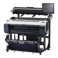
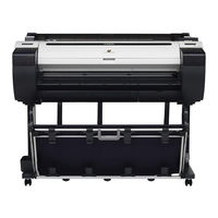
Canon iPF750 - imagePROGRAF Color Inkjet Printer
Canon imagePROGRAF iPF750 MFP M40
Canon iPF755 - imagePROGRAF Color Inkjet Printer
Canon iPF710 - imagePROGRAF Color Inkjet Printer
Canon iPF720 - imagePROGRAF Color Inkjet Printer
Canon iPF700
Canon imagePROGRAF iPF760
Canon image Prograf iPF785 Series
Canon imagePROGRAF iPF770
Canon iPF760 series
Canon Categories
Printer
Digital Camera
All in One Printer
Camcorder
Scanner
More Canon Manuals
Login
Sign In
OR
Sign in with Facebook
Sign in with Google
Upload manual
Upload from disk
Upload from URL