Sign In
Upload
Manuals
Brands
Brocade Communications Systems Manuals
Switch
G620
Brocade Communications Systems G620 Manuals
Manuals and User Guides for Brocade Communications Systems G620. We have
2
Brocade Communications Systems G620 manuals available for free PDF download: Hardware Installation Manual
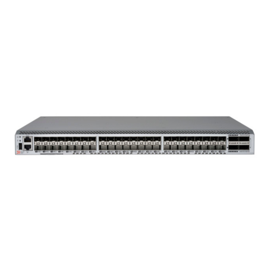
Brocade Communications Systems G620 Hardware Installation Manual (94 pages)
Brand:
Brocade Communications Systems
| Category:
Switch
| Size: 2.02 MB
Table of Contents
Table of Contents
3
Preface
7
Document Conventions
7
Notes, Cautions, and Warnings
7
Text Formatting Conventions
7
Command Syntax Conventions
8
Brocade Resources
8
Document Feedback
8
Contacting Brocade Technical Support
9
Brocade Customers
9
Brocade OEM Customers
9
About this Document
11
Supported Hardware and Software
11
What's New in this Document
11
Device Overview
13
Hardware Features
13
License Options
14
Port-Side View
14
Nonport-Side View
15
Device Management Options
16
Preparing for the Installation
17
Safety Precautions
17
General Precautions
17
ESD Precautions
18
Power Precautions
18
Lifting and Weight-Related Precautions
19
Laser Precautions
20
Facility Requirements
20
Quick Installation Checklist
20
Pre-Installation Tasks
20
Installation and Initial Configuration
21
Shipping Carton Contents
22
Mounting the Device
25
Mounting Options
25
Precautions Specific to Mounting
25
Standalone Installation
26
Installing the Universal Four-Post Rack Kit (XBR-R000296)
26
Time and Items Required
27
Parts List
27
Flush-Front Mounting
29
Flush-Rear (Recessed) Mounting
34
Installing the Universal Two-Post Rack Kit (XBR-R000294)
39
Time and Items Required
40
Parts List
40
Flush-Front Mounting
41
MID-Mounting
45
Initial Setup and Verification
51
Items Required
51
Providing Power to the Device
51
Establishing a First-Time Serial Connection
52
Configuring the IP Address
53
Using DHCP to Set the IP Address
53
Setting a Static IP Address
53
Setting the Date and Time
53
Setting the Time Zone
54
Synchronizing Local Time with an External Source
55
Customizing the Chassis Name and Switch Name
55
Establishing an Ethernet Connection
55
Setting the Domain ID
56
Verifying Correct Operation
56
Backing up the Configuration
58
Powering down the Device
58
Installing Transceivers and Cables
59
Time and Items Required
59
Precautions Specific to Transceivers and Cables
60
Cleaning the Fiber-Optic Connectors
60
Managing Cables
60
Installing an SFP+ Transceiver
61
Replacing an SFP+ Transceiver
61
Installing a QSFP Transceiver
62
Replacing a QSFP Transceiver
63
Verifying the Operation of New Transceivers
64
Monitoring the Device
65
Interpreting Port-Side Leds
65
System Power LED
65
System Status LED
66
FC Port Status LED
66
QSFP Port Status LED
67
Interpreting Nonport-Side Leds
68
Power Supply and Fan Assembly Status LED
68
Interpreting the POST Results
68
Interpreting the BOOT Results
69
Running Diagnostic Tests
69
Power Supply and Fan Assembly
71
Power Supply and Fan Assembly Overview
71
Precautions Specific to the Power Supply and Fan Assemblies
72
Identifying the Airflow Direction
73
Power Supply and Fan Assembly Status LED
73
Power Supply and Fan Assembly Unit Fault Indicators
74
Power Supply and Fan Assembly Task Guide
74
Installing an Additional Power Supply and Fan Assembly (Hot-Install)
74
Replacing a Power Supply and Fan Assembly (Hot-Swap)
74
Replacing both Power Supply and Fan Assemblies (Cold-Swap)
74
Time and Items Required
75
Recording Power Supply and Fan Assembly Critical Information
75
Removing a Power Supply and Fan Assembly
75
Inserting a New Power Supply and Fan Assembly
76
Verifying the Operation of the Power Supply and Fan Assemblies
78
Brocade G620 Technical Specifications
79
System Specifications
79
Fibre Channel
79
Other
80
Leds
80
Weight and Physical Dimensions
80
Environmental Requirements
80
Power Supply Specifications (Per PSU)
81
Power Consumption (Typical Configuration)
81
Power Consumption (Maximum Configuration)
82
Power Consumption (Idle Configuration)
82
Data Port Specifications (Fibre Channel)
82
Fibre Channel Data Transmission Ranges
82
Serial Port Specifications (Pinout RJ-45)
83
Serial Port Specifications (Protocol)
83
Memory Specifications
84
Regulatory Compliance (EMC)
84
Regulatory Compliance (Safety)
84
Regulatory Compliance (Environmental)
84
Regulatory Statements
85
BSMI Statement (Taiwan)
85
Canadian Requirements
85
CE Statement
85
China CCC Statement
86
China ROHS
86
FCC Warning (US Only)
86
Germany Statement
87
KCC Statement (Republic of Korea)
87
VCCI Statement
87
Cautions and Danger Notices
89
Danger Notices
89
General Dangers
89
Electrical Dangers
89
Dangers Related to Equipment Weight
91
Laser Dangers
91
Cautions
91
General Cautions
91
Electrical Cautions
92
Advertisement
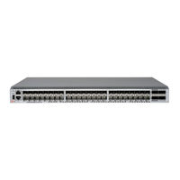
Brocade Communications Systems G620 Hardware Installation Manual (93 pages)
Brand:
Brocade Communications Systems
| Category:
Switch
| Size: 3.63 MB
Table of Contents
Table of Contents
3
Introduction
6
About this Document
6
What Is New in this Document
6
Supported Hardware and Software
6
Notes, Cautions, and Danger Notices
7
Contacting Technical Support for Your Brocade Product
7
Document Feedback
8
Device Overview
9
Hardware Features
9
License Options
10
Port-Side View
10
Nonport-Side View
11
Device Management Options
12
Preparing for Installation
13
Safety Precautions
13
General Precautions
13
ESD Precautions
14
Power Precautions
14
Lifting and Weight-Related Precautions
15
Laser Precautions
16
Facility Requirements
16
Quick Installation Checklist
16
Preinstallation Tasks
16
Installation and Initial Configuration
17
Shipping Carton Contents
18
Mounting the Device
19
Mounting Options
19
Precautions Specific to Mounting
19
Stand-Alone Installation
20
Installing the Universal Four-Post Rack Kit (XBR-R000296)
20
Time and Items Required
21
Parts List
21
Flush-Front Mounting
23
Flush-Rear (Recessed) Mounting
28
Installing the Universal Two-Post Rack Kit (XBR-R000294)
35
Time and Items Required
36
Parts List
36
Flush-Front Mounting
37
MID-Mounting
42
Initial Setup and Verification
47
Items Required
47
Providing Power to the Device
47
Establishing a First-Time Serial Connection
48
Configuring the IP Address
49
Using DHCP to Set the IP Address
49
Setting a Static IP Address
49
Setting the Date and Time
49
Setting the Time Zone
50
Synchronizing the Local Time with an External Source
51
Customizing the Chassis Name and Switch Name
51
Establishing an Ethernet Connection
51
Setting the Domain ID
52
Verifying Correct Operation
52
Backing up the Configuration
53
Powering down the Device
54
Installing Transceivers and Cables
55
Time and Items Required
55
Precautions Specific to Transceivers and Cables
56
Cleaning the Fiber-Optic Connectors
56
Managing Cables
56
Installing an SFP+ Transceiver
57
Replacing an SFP+ Transceiver
59
Installing a QSFP Transceiver
60
Replacing a QSFP Transceiver
61
Verifying the Operation of New Transceivers
63
Monitoring the Device
64
Interpreting Port-Side Leds
64
System Power LED
64
System Status LED
65
Management Port Leds
65
FC Port Status Leds
65
QSFP Port Status Leds
66
Interpreting Nonport-Side Leds
67
Interpreting POST Results
67
Interpreting Boot Results
68
Running Diagnostic Tests
68
Power Supply and Fan Assembly
69
Power Supply and Fan Assembly Overview
69
Precautions Specific to the Power Supply and Fan Assemblies
70
Identifying the Airflow Direction
70
Power Supply and Fan Assembly Fault Indicators
71
Power Supply and Fan Assembly Task Guide
71
Installing an Additional Power Supply and Fan Assembly (Hot-Install)
71
Replacing a Power Supply and Fan Assembly (Hot-Swap)
72
Replacing both Power Supply and Fan Assemblies (Cold-Swap)
72
Time and Items Required
72
Recording Critical Information about the Power Supply and Fan Assembly
72
Removing a Power Supply and Fan Assembly
73
Inserting a New Power Supply and Fan Assembly
73
Verifying the Operation of the Power Supply and Fan Assemblies
75
Brocade G620 Switch Technical Specifications
76
System Specifications
76
Fibre Channel Ports
76
Other Ports
77
Leds
77
Cables, Connectors, and Adapters
77
Weight and Physical Dimensions
77
Environmental Requirements
77
Power Supply Specifications (Per PSU)
78
Power Consumption (Typical Configuration)
78
Power Consumption (Maximum Configuration)
78
Power Consumption (Idle Configuration)
79
Data Port Specifications (Fibre Channel)
79
Fibre Channel Data Transmission Ranges
79
Serial Port Specifications (Pinout RJ-45)
80
Serial Port Specifications (Protocol)
80
Memory Specifications
80
Regulatory Compliance (EMC)
81
Regulatory Compliance (Safety)
81
Regulatory Compliance (Environmental)
81
Regulatory Statements
83
BSMI Statement (Taiwan)
83
Canadian Requirements
83
CE Statement
83
China CCC Statement
84
China ROHS
84
FCC Warning (U.S. Only)
84
Germany Statement
85
KCC Statement (Republic of Korea)
85
Taiwan ROHS Certification
86
VCCI Statement
87
Cautions and Danger Notices
88
Danger Notices
88
General Dangers
88
Electrical Dangers
88
Dangers Related to Equipment Weight
89
Laser Dangers
90
Cautions
90
General Cautions
90
Electrical Cautions
91
Revision History
93
53-1003990-16; 29 March 2019
93
53-1003990-15; 13 February 2019
93
53-1003990-14; 4 December 2018
93
53-1003990-13; 20 September 2018
93
Advertisement
Related Products
Brocade Communications Systems G610
Brocade Communications Systems Gateway
Brocade Communications Systems 200E Series
Brocade Communications Systems 300
Brocade Communications Systems 4100 Series
Brocade Communications Systems 48000
Brocade Communications Systems 4900
Brocade Communications Systems 5000 Series
Brocade Communications Systems 5300
Brocade Communications Systems 5410
Brocade Communications Systems Categories
Switch
Software
Network Router
Storage
Server
More Brocade Communications Systems Manuals
Login
Sign In
OR
Sign in with Facebook
Sign in with Google
Upload manual
Upload from disk
Upload from URL