Sign In
Upload
Manuals
Brands
Bradford White Manuals
Boiler
Brute MagnaTech BMGH1600
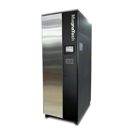
Bradford White Brute MagnaTech BMGH1600 Manuals
Manuals and User Guides for Bradford White Brute MagnaTech BMGH1600. We have
3
Bradford White Brute MagnaTech BMGH1600 manuals available for free PDF download: Installation And Operation Instructions Manual, User Manual
Bradford White Brute MagnaTech BMGH1600 Installation And Operation Instructions Manual (144 pages)
Brand:
Bradford White
| Category:
Boiler
| Size: 33.65 MB
Table of Contents
Table of Contents
2
SECTION 1 General Information
5
A Introduction
5
B M Odel Identification
5
C Warranty
5
E Unit Overview
8
F Gas Train Components
9
G Venting Dimensions & Sizing
10
H Dimensions
10
K Clearances
13
SECTION 2 Venting and Combustion Air 2.A General Venting Information
14
B Vent and Air Pipe Material
14
Enting Reqs Unique to Canada
14
B.1.A Flue Gas Sampling Port
14
B.1.B Exhaust Vent Terminal
15
C Vent and Air Pipe Sizing
16
Category Lv Vent Sizes
17
Category II Vent Sizes
17
Common Venting
17
Common Vent Test
18
Combustion Air
19
C.5.A Combustion Air From Room
19
C.5.B Ducted Combustion Air
20
D L Ocating the Vent
20
L Ocating the Vent and Combustion Air Terminals
20
Side-Wall Vent Terminal
20
Side-Wall Combustion Air Terminal
22
Vertical Vent Terminal
22
Ertical Combustion Air Terminal
22
E Outdoor Installation
23
F Installations in the Commonwealth of Massachusetts
23
SECTION 3 Gas Supply and Piping
24
A Gas Supply and Piping
24
B Gas Pipe Sizing
25
SECTION 4 Water Flow & Headloss Data
26
A General Water Flow Information
26
B Boiler Water Flow & Headloss Data
26
C Water Heater Water Flow and Headloss Data
27
SECTION 5 Piping
28
Boiler Water Piping
28
Boiler Water Connections
28
Cold Water Make-Up
28
Freeze Protection
28
Suggested Boiler Piping Schematics
29
W Ater Heaters
33
Water Quality
33
Heater Water Connections
33
Cold Water Make-Up
33
Freeze Protection
34
Suggested Piping Schematics
34
SECTION 6 Condensate Drain Trap
36
Condensate Trap Instructions
37
SECTION 7 Electrical Connections
38
Installation Warnings
38
Main Power Connections
39
Main Power Data
40
Control Panel Layout
40
Field Connections
40
Power
40
Dry Contacts
40
Temperature Sensors
42
Heat Demands
43
Analog In And Analog Out
43
Dry Contacts. Run & Alarm
43
Rs 485, Cascade
44
Rs485 Bms
44
Modbus to Bacnet Memory Map
45
W Iring Diagrams
48
High Voltage Wiring Diagrams
52
Ladder Diagrams
59
SECTION 8 Control Operation
66
The Home Screen
66
Home Screen Active Icons
66
Keypad Operations
67
8 B Login to Lock / Unlock the Display . 64
69
Quick Start
69
Quick Start Ch (Central Heat)
69
C.2.A Quick Start Ch1 (Central Heat, One)
70
C.2.B Quick Start Ch2 (Central Heat, Two)
70
Quick Start Dhw (Dom Hot Water)
70
Outdoor Reset
71
Warm Weather Shut Down
71
Anti-Short Cycle
72
Time & Date
72
D Configuration
73
Central Heat)
74
D.1.A CH1 (Central Heat, One)
74
D.1.A.3 Pid Parameters
75
D.1.B CH2 (Central Heat, Two)
75
DHW (Domestic Hot Water)
75
Outdoor Reset
76
Cascade (Lead / Lag)
77
D.4.A Cascade Ch (Central Heat)
82
D.4.A.1 Cascade Ch Lead Settings
83
D.4.A.1.A Cascade Base / Drop Load
84
D.4.B Cascade Dhw (Dom Hot Water)
84
D.4.C Cascade Rotation
85
D.4.C.1 Cascade Rotation Setup
85
D.4.D Cascade Redundancy
86
Hybrid
86
Pumps
87
D.6.A Dhw Recirculation
88
D.6.B Variable Speed Pump Control
88
Manual Firing Rate
89
Temp Limits
89
D.8.A Delta T Parameters
90
D.8.B Flue Limitation Parameters
90
D.8.C Outlet Limitation Parameters
90
External
91
D.9.A External - Remote Set Point
92
D.9.B External Firing Rate
93
Time & Date
93
Miscellaneous Features
94
D.11.A Demand Priority
95
D.11.B Anti-Short Cycle
95
D.11.C Warm Weather
96
D.11.D Com Port, Bms
97
D.11.E Temperature Conversion
98
D.11.F Anti-Frost
98
D.11.G Trim (O 2 Trim Enable / Disable)
99
Login
99
E Service Screens
100
Burner
100
Digital I/O ( Input / Output )
101
Analog I/O
102
Screen Settings Timeout
103
History
103
Restart Touchscreen & Recalibrate
103
Factory Reset
104
Hmi Model Oem Only
104
Bic Model Oem Only
104
Both Model. OEM Only
104
O2 (Trim Set Point)
104
Lmv
104
Messages and USB
105
Messages
105
Usb Functionality
105
Active Demands
106
SECTION 9 Parameter Tables
107
SECTION 10 Initial Startup Instructions
113
Filling The Boiler System
113
Initial Operation
114
Initial Burner Operation
114
Combustion Setup Procedure Hi Fire, Low Fire
115
Shutting Down The Unit
117
Restarting The Unit
117
Controllers
117
Transmitters
118
SECTION 11 Maintenance
119
System Maintenance
119
Maintenance Notes
119
Burner
119
Gas Train Components
119
Controller
120
Spark Ignition Electrodes
120
Flame Sensor
120
Blower Model 1600
120
Blower Model 2000-4000
120
Heat Exchanger Tubes
121
Gas Pressure Switches
121
Pressure Transmitters
122
Oxygen Sensor
122
High Temperature Limits (Optional)
122
SECTION 12 Troubleshooting
123
Lockouts And Errors
123
Lmv Errors
125
SECTION 13 Replacement Parts
130
General Information
130
Component Illustrations, Parts Lists, and Part Numbers
130
Advertisement
Bradford White Brute MagnaTech BMGH1600 Installation And Operation Instructions Manual (120 pages)
Brand:
Bradford White
| Category:
Water Heater
| Size: 8.36 MB
Table of Contents
Table of Contents
2
Section 1 - GENERAL INFORMATION
5
Introduction
5
Safety Notes
5
The Rating Plate (Model Nomenclature)
6
Warranty
6
Unit Overviews ( All Sizes )
7
Dimensions
10
Unpacking and the Installation Kit
11
Section 2 - LOCATING the APPLIANCE
12
Locating the Appliance
12
Correct Vent Distance from Outside Wall or Roof Termination
12
Section 3 - VENTING and COMBUSTION AIR
13
General Venting
13
Combustion Air
14
Combustion Air from Room
14
Ducted Combustion Air
15
Venting
15
Common Venting
16
Venting Requirements Unique to Canada
16
Locating the Vent and Combustion Air Terminals
17
Side Wall Vent Terminal
17
Side Wall Combustion Air Terminal
19
Vertical Vent Terminal
19
Vertical Combustion Air Terminal
19
Installations in the Commonwealth of Massachusetts
20
Common Vent Test
20
Outdoor Installation
22
Section 4 - GAS SUPPLY and PIPING
22
Gas Supply and Piping
22
Section 5 - WATER FLOW REQUIREMENTS
24
Boiler Flow and Head Requirements
24
Water Heater Flow and Head Requirements
25
Section 6 - WATER CONNECTIONS
26
Connections
26
Boiler Cold Water Make-Up
26
Boiler Freeze Protection
26
Condensate Drain Trap
27
Boiler Suggested Piping Schematics
27
Section 7 - WATER CONNECTIONS
32
Vol Water Water Quality
32
Vol Water Suggested Piping Schematics
32
Vol Water Piping Requirements
32
Vol Water Cold Water Make-Up
33
Vol Water Freeze Protection
33
Vol Water Water Flow
34
Condensate Drain Trap
34
Section 8 - ELECTRICAL CONNECTIONS
35
Installation Warnings
35
Main Power Connections
35
Pump Connections and Operation
36
Field Wiring
37
Field Connections for Single Systems
38
Field Connections for Lead Lag Systems
38
Control Panel Layout
39
Building Automation Systems Connections
40
Lead Lag Connections
41
Wiring Diagrams
42
High Voltage Wiring Diagrams
46
Ladder Diagrams
53
Section 9 - NAVIGATING the TOUCH SCREEN
60
The Touch Screen
60
Using the Touch Screen
60
Parameters
62
Parameters
63
Controllers
64
Setting the Date and Time on the System Display
65
High Limits
68
Stack Limits
68
Delta T Limits
68
Burner Control Ignition
69
Parameter Defaults and Ranges
73
Variable Speed Flow Control (V.S.P.C.) System
78
Combustion Setup Procedure
79
Section 10 - INITIAL STARTUP INSTRUCTIONS
82
Filling the Boiler System
82
Initial Operation
83
Initial Burner Operation
83
Combustion Setup Procedure
83
Shutting down the Unit
83
Restarting the Unit
83
Section 11 - MAINTENANCE
84
System Maintenance
84
Maintenance Notes
84
Burner
84
Modulating Gas Valve/ Venturi
84
Controller
85
Spark Ignition Electrodes
85
Flame Sensor
85
Blower Model 1600
85
Blower Model 4000
85
Heat Exchanger Tubes
86
Gas Pressure Switches
86
Battery Back up for Date and Time
87
Section 12 - TROUBLESHOOTING
88
About Lockouts, Holds, and Alerts
88
Responding to a Lockout, Hold, or Alert
88
Viewing the Lockout and Alert Histories
88
Troubleshooting Table
90
Diagnostic Tests and Input/Output Indicators
99
Lead/Lag Diagnostics
100
Statistics
100
Analysis
100
Control Snapshot
101
Operating Sequence
101
Section 13 - REPLACEMENT PARTS
102
General Information
102
Component Illustrations, Parts Lists, and Part Numbers
103
Frame and Jacket Assembly
103
Final Assembly
105
Waterway Outlet Assembly
106
Blower Assy, Model 1600
107
Blower Assy, Model 2000
108
Gas Train Assembly, Models 1600 Thru 3000
113
Control Panel Assembly
116
Distribution Box Assemblies
118
Bradford White Brute MagnaTech BMGH1600 User Manual (8 pages)
Modulating Boiler/Water Heater
Brand:
Bradford White
| Category:
Boiler
| Size: 2.55 MB
Table of Contents
Table of Contents
2
Familiarizing Yourself with the Magnatech
2
For Your Safety
3
Please Read this before Operating
3
What to Do if You Smell Gas
3
Lighting the Unit
3
Turning off the Gas to the Unit
3
Pour Votre Sécurité, Lisez Avant de Mettre en Marche
4
Que Faire si Vous Sentez Une Odeur de Gaz
4
Instructions de Mise en Marche
4
Fermeture de L'alimentation en Gaz
4
Shutting down the Magnatech
5
Restarting the Magnatech
5
In the Event of Power Failure
5
The Touch Screen and Indicators
6
About Lockouts, Holds, and Alerts
7
Care, Inspection, and Service
8
Advertisement
Advertisement
Related Products
Bradford White Brute MagnaTech BMGH2000
Bradford White Brute MagnaTech BMGH2500
Bradford White Brute MagnaTech BMGH3000
Bradford White Brute MagnaTech BMGH3500
Bradford White Brute MagnaTech BMGH4000
Bradford White Brute MagnaTech BMGV1600
Bradford White Brute MagnaTech BMGV2000
Bradford White Brute MagnaTech BMGV2500
Bradford White Brute MagnaTech BMGV3000
Bradford White Brute MagnaTech BMGV3500
Bradford White Categories
Water Heater
Boiler
Heat Pump
Gas Heater
Electric Heater
More Bradford White Manuals
Login
Sign In
OR
Sign in with Facebook
Sign in with Google
Upload manual
Upload from disk
Upload from URL