Sign In
Upload
Manuals
Brands
Baumer Manuals
Media Converter
HOG 86
Baumer HOG 86 Manuals
Manuals and User Guides for Baumer HOG 86. We have
3
Baumer HOG 86 manuals available for free PDF download: Mounting And Operating Instructions, Installation And Operating Instructions Manual
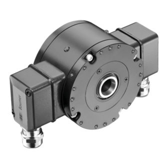
Baumer HOG 86 Installation And Operating Instructions Manual (44 pages)
Incremental Encoder
Brand:
Baumer
| Category:
Media Converter
| Size: 6.14 MB
Table of Contents
Inhaltsverzeichnis
2
Table of Contents
2
Allgemeine Hinweise
4
Betrieb in Explosionsgefährdeten Bereichen
6
Sicherheitshinweise
8
Vorbereitung
10
Lieferumfang
10
Zur Montage Erforderlich (nicht IM Lieferumfang Enthalten)
11
Montagesets zur Befestigung einer Drehmomentstütze am Drehgeber (nicht IM Lieferumfang Enthalten)
12
Montageset zur Befestigung einer Drehmomentstütze an der Antriebsseite (nicht IM Lieferumfang Enthalten)
13
Zur Demontage Erforderlich (nicht IM Lieferumfang Enthalten)
13
Erforderliches Werkzeug (nicht IM Lieferumfang Enthalten)
13
Montage
14
Schritt 1
14
Schritt 2
14
Anbau mit Stützblech (Zubehör)
14
Schritt 2A
14
Anbaubeispiele mit Stützblech
15
Anbau mit Stützblech (Zubehör)
15
Schritt 2B
15
Anbau Direkt
16
Anbaubeispiele bei Direktem Anbau
16
Schritt 3
17
Version mit Einseitig Offener Hohlwelle
17
Version mit Konuswelle
18
Schritt
18
Anbau mit Stützblech
19
Anbau Direkt
19
Schritt
19
Anbau Direkt
21
Hinweis zur Vermeidung von Messfehlern
22
Schritt 6
23
Abmessungen
24
HOG 86 T und HOG 86.2 T (EMS)
24
HOG 86 F und HOG 86.2 F (EMS)
25
HOG 86 K und HOG 86.2 K (EMS)
26
HOG 86 M T und HOG 86.2 M T (EMS), Redundante Abtastung
27
HOG 86 M F und HOG 86.2 M F (EMS), Redundante Abtastung
28
Anbaumöglichkeiten
29
Stützbleche (Zubehör)
29
Elektrischer Anschluss
30
Montage Anschlusskabel
30
Version mit Klemmenkasten
30
Schritt 1
30
Schritt 2
30
Version mit Flanschdose
31
Schritt 1
31
Schritt 2
32
Beschreibung der Anschlüsse
32
Ausgangssignale
33
Anschlussbelegung
33
Version mit Klemmenkasten
33
Ohne EMS - HOG 86 (M) T
33
Mit EMS - HOG 86.2 (M) T
33
Version mit Flanschdose - HOG 86(.2) F
34
Version mit Anschlusskabel - HOG 86(.2) K
34
LED-Anzeige / Fehlerausgang (Option EMS - Enhanced Monitoring System)
35
Sensorkabel HEK 8 (Zubehör)
36
Demontage
37
Anhang
41
EU-Konformitätserklärung
41
Technische Daten
42
Technische Daten - Elektrisch
42
Technische Daten - Mechanisch
42
Zubehör
44
Table of Contents
5
General Notes
5
Operation in Potentially Explosive Environments
7
Security Indications
9
Preparation
10
Scope of Delivery
10
Required for Mounting (Not Included in Scope of Delivery)
11
Mounting Kits to Fix a Torque Arm at the Encoder (Not Included in Scope of Delivery)
12
Mounting Kit to Fix a Torque Arm on the Drive Side (Not Included in Scope of Delivery)
13
Required for Dismounting (Not Included in Scope of Delivery)
13
Required Tools (Not Included in Scope of Delivery)
13
Mounting
14
Step 1
14
Step 2
14
Mounting with Support Plate (Accessory) Step 2A
14
Mounting Examples with Support Plate
15
Mounting with Support Plate
15
(Accessory) Step 2B
15
Direct Mounting
16
Mounting Examples at Direct Mounting
16
Step 3
17
Blind Hollow Shaft Version
17
Cone Shaft Version
18
Step 4
18
Mounting with Support Plate
19
Direct Mounting
19
Step 5
19
Mounting with Support Plate
20
Schritt 5
20
Direct Mounting
21
How to Prevent Measurement Errors
22
Step 6
23
Dimensions
24
HOG 86 T and HOG 86.2 T (EMS)
24
HOG 86 F and HOG 86.2 F (EMS)
25
HOG 86 K and HOG 86.2 K (EMS)
26
HOG 86 M T and HOG 86.2 M T (EMS), Redundant Sensing
27
HOG 86 M F and HOG 86.2 M F (EMS), Redundant Sensing
28
Mounting Possibilities
29
Support Plates (Accessories)
29
Electrical Connection
30
Mounting Connecting Cable
30
Version with Terminal Box
30
Step 1
30
Step 2
30
Version with Flange Connector
31
Step 1
31
Step 2
32
Terminal Significance
32
Output Signals
33
Terminal Assignment
33
Version with Terminal Box
33
Without EMS - HOG 86 (M) T
33
With EMS - HOG 86.2 (M) T
33
Version with Flange Connector - HOG 86(.2) F
34
Version with Connecting Cable - HOG 86(.2) K
34
LED Status / Error Output (Option EMS - Enhanced Monitoring System)
35
Sensor Cable HEK 8 (Accessory)
36
Dismounting
37
Appendix
41
EU Declaration of Conformity
41
Technical Data
43
Technical Data - Electrical Ratings
43
Technical Data - Mechanical Design
43
Accessories
44
Advertisement
Baumer HOG 86 Mounting And Operating Instructions (44 pages)
Incremental Encoder
Brand:
Baumer
| Category:
Media Converter
| Size: 8.83 MB
Table of Contents
Table of Contents
2
Allgemeine Hinweise
4
General Notes
5
Betrieb in Explosionsgefährdeten Bereichen
6
Operation in Potentially Explosive Environments
7
Sicherheitshinweise
8
Security Indications
9
Vorbereitung
10
Lieferumfang
10
Preparation
10
Scope of Delivery
10
Zur Montage Erforderlich (nicht IM Lieferumfang Enthalten)
11
Required for Mounting (Not Included in Scope of Delivery)
11
Montagesets zur Befestigung einer Drehmomentstütze am Gerät (nicht IM Lieferumfang Enthalten)
12
Mounting Kits To Fix A Torque Arm At The
12
(Not Included in Scope of Delivery)
12
Montageset zur Befestigung einer Drehmomentstütze an der Antriebsseite (nicht IM Lieferumfang Enthalten)
13
Zur Demontage Erforderlich (nicht IM Lieferumfang Enthalten)
13
Erforderliches Werkzeug (nicht IM Lieferumfang Enthalten)
13
Mounting Kit to Fix a Torque Arm on the Drive Side (Not Included in Scope of Delivery)
13
Required for Dismounting (Not Included in Scope of Delivery)
13
Required Tools (Not Included in Scope of Delivery)
13
Montage
14
Schritt 1
14
Schritt 2
14
Stützblech-Montage (Zubehör)
14
Schritt 2A
14
Mounting
14
Step 1
14
Step 2
14
Support Plate Mounting (Accessory)
14
Step 2A
14
Montagebeispiele mit Stützblech
15
Stützblech-Montage (Zubehör)
15
Schritt 2B
15
Mounting Examples with Support Plate
15
Support Plate Mounting (Accessory)
15
Step 2B
15
Direkte Montage
16
Montagebeispiele bei Direkter Montage
16
Direct Mounting
16
Mounting Examples at Direct Mounting
16
Schritt 3
17
Einseitig Offene Hohlwelle
17
Step 3
17
Blind Hollow Shaft
17
Konuswelle
18
Cone Shaft
18
Schritt 4
19
Stützblech-Montage
19
Direkte Montage
19
Schritt 5
19
Step 4
19
Support Plate Mounting
19
Direct Mounting
19
Stützblech-Montage
20
Step 5
20
Support Plate Mounting
20
Direkte Montage
21
Direct Mounting
21
Hinweis zur Vermeidung von Messfehlern
22
How to Prevent Measurement Errors
22
Schritt 6
23
Step 6
23
Abmessungen
24
Mit Klemmenkasten HOG 86
24
Dimensions
24
With Terminal Box HOG 86
24
Mit Flanschdose HOG 86
25
With Flange Connector HOG 86
25
Mit Anschlusskabel HOG 86
26
With Connecting Cable HOG 86.. K
26
Option M: Redundante Abtastung mit Klemmenkästen HOG 86
27
Option M: Redundant Sensing with Terminal Boxes HOG 86
27
Option M: Redundante Abtastung mit Flanschdosen HOG 86
28
Option M: Redundant Sensing with Flange Connectors HOG 86
28
Montagemöglichkeiten
29
Stützbleche (Zubehör)
29
Mounting Possibilities
29
Support Plates (Accessories)
29
Elektrischer Anschluss
30
Kabelanschluss
30
Mit Klemmenkasten
30
Schritt 1
30
Schritt 2
30
Electrical Connection
30
Cable Connection
30
With Terminal Box
30
Step 1
30
Step 2
30
Mit Flanschdose
31
With Flange Connector
31
Step 1
31
Schritt 1
32
Schritt 2
32
Beschreibung der Anschlüsse
32
Step 2
32
Terminal Significance
32
Ausgangssignale
33
Anschlussbelegung
33
Klemmenkasten
33
Standard
33
Option EMS
33
Option Ems
33
Output Signals
33
Terminal Assignment
33
Terminal Box
33
Pinbelegung Flanschdose
34
Anschlusskabelbelegung HOG 86
34
Pin Assignment Flange Connector
34
Hog 86.. F
34
Connecting Cable Assignment HOG 86
34
Option EMS (Enhanced Monitoring System): Status LED / Fehlerausgang
35
Option EMS (Enhanced Monitoring System): Status LED / Error Output
35
Sensorkabel HEK 8 (Zubehör)
36
Sensor Cable HEK 8 (Accessory)
36
Demontage
37
Dismounting
37
EU-Konformitätserklärung
41
EU Declaration of Conformity
41
Technische Daten
42
Technische Daten - Elektrisch
42
Technische Daten - Mechanisch
42
Technical Data
43
Technical Data - Electrical Ratings
43
Technical Data - Mechanical Design
43
Zubehör
44
Accessories
44
Baumer HOG 86 Mounting And Operating Instructions (44 pages)
Incremental encoder
Brand:
Baumer
| Category:
Media Converter
| Size: 6.11 MB
Table of Contents
Inhaltsverzeichnis
2
Table of Contents
2
Allgemeine Hinweise
4
Betrieb in Explosionsgefährdeten Bereichen
6
Sicherheitshinweise
8
Vorbereitung
10
Lieferumfang
10
Zur Montage Erforderlich (nicht IM Lieferumfang Enthalten)
11
Montagesets zur Befestigung einer Drehmomentstütze am Gerät (nicht IM Lieferumfang Enthalten)
12
Montageset zur Befestigung einer Drehmomentstütze an der Antriebsseite (nicht IM Lieferumfang Enthalten)
13
Zur Demontage Erforderlich (nicht IM Lieferumfang Enthalten)
13
Erforderliches Werkzeug (nicht IM Lieferumfang Enthalten)
13
Montage
14
Schritt 1
14
Schritt 2
14
Stützblech-Montage (Zubehör)
14
Schritt 2A
14
Montagebeispiele mit Stützblech
15
Stützblech-Montage (Zubehör)
15
Schritt 2B
15
Direkte Montage
16
Montagebeispiele bei Direkter Montage
16
Schritt 3
17
Einseitig Offene Hohlwelle
17
Schritt 5
17
Direkte Montage
19
Stützblech-Montage
20
Hinweis zur Vermeidung von Messfehlern
22
Schritt 6
23
Abmessungen
24
Mit Klemmenkasten HOG 86
24
Mit Flanschdose HOG 86.. F
25
Mit Anschlusskabel HOG 86.. K
26
Option M: Redundante Abtastung mit Klemmenkästen HOG 86
27
Option M: Redundante Abtastung mit Flanschdosen HOG 86
28
Montagemöglichkeiten
29
Stützbleche (Zubehör)
29
Elektrischer Anschluss
30
Kabelanschluss
30
Mit Klemmenkasten
30
Schritt 1
30
Schritt 2
30
Mit Flanschdose
31
Schritt 1
31
Schritt 2
32
Beschreibung der Anschlüsse
32
Ausgangssignale
33
Anschlussbelegung
33
Klemmenkasten
33
Standard
33
Option EMS
33
Pinbelegung Flanschdose
34
Anschlusskabelbelegung HOG 86
34
Option EMS (Enhanced Monitoring System): Status LED / Fehlerausgang
35
Sensorkabel HEK 8 (Zubehör)
36
Demontage
37
EU-Konformitätserklärung
41
Technische Daten
42
Technische Daten - Elektrisch
42
Technische Daten - Mechanisch
42
Zubehör
44
Table of Contents
5
General Notes
5
Operation in Potentially Explosive Environments
7
Security Indications
9
Preparation
10
Scope of Delivery
10
Required for Mounting (Not Included in Scope of Delivery)
11
Mounting Kits To Fix A Torque Arm At The
12
(Not Included in Scope of Delivery)
12
Mounting Kit to Fix a Torque Arm on the Drive Side (Not Included in Scope of Delivery)
13
Required for Dismounting (Not Included in Scope of Delivery)
13
Required Tools (Not Included in Scope of Delivery)
13
Mounting
14
Step 1
14
Step 2
14
Support Plate Mounting (Accessory)
14
Step 2A
14
Mounting Examples with Support Plate
15
Support Plate Mounting (Accessory)
15
Step 2B
15
Direct Mounting
16
Mounting Examples at Direct Mounting
16
Step 3
17
Blind Hollow Shaft
17
Cone Shaft
18
Step 4
19
Support Plate Mounting
19
Direct Mounting
19
Step 5
20
Support Plate Mounting
20
Direct Mounting
21
How to Prevent Measurement Errors
22
Step 6
23
Dimensions
24
With Terminal Box HOG 86.. T
24
With Flange Connector HOG 86
25
With Connecting Cable HOG 86.. K
26
Option M: Redundant Sensing with Terminal Boxes HOG 86
27
Option M: Redundant Sensing with Flange Connectors HOG 86
28
Mounting Possibilities
29
Support Plates (Accessories)
29
Electrical Connection
30
Cable Connection
30
With Terminal Box
30
Step 1
30
Step 2
30
With Flange Connector
31
Step 1
31
Step 2
32
Terminal Significance
32
Option Ems
33
Output Signals
33
Terminal Assignment
33
Terminal Box
33
Pin Assignment Flange Connector
34
Hog 86
34
Connecting Cable Assignment HOG 86
34
Option EMS (Enhanced Monitoring System): Status LED / Error Output
35
Sensor Cable HEK 8 (Accessory)
36
Dismounting
37
EU Declaration of Conformity
41
Technical Data
43
Technical Data - Electrical Ratings
43
Technical Data - Mechanical Design
43
Accessories
44
Advertisement
Advertisement
Related Products
Baumer Hubner HOG 86+FSL
Baumer HUBNER BERLIN HOG 8
Baumer Hubner Berlin HOG 86 + DSL
Baumer Hubner Berlin HOG 86E
Baumer Hubner HOG 16
Baumer Hubner Berlin HOG 163
Baumer HOGS 75 KC
Baumer HUBNER BERLIN HOG 10 - Niro
Baumer HOGS 100 S
Baumer HOG 10.2 G
Baumer Categories
Accessories
Media Converter
Security Sensors
Measuring Instruments
Portable Generator
More Baumer Manuals
Login
Sign In
OR
Sign in with Facebook
Sign in with Google
Upload manual
Upload from disk
Upload from URL