Sign In
Upload
Manuals
Brands
Agilent Technologies Manuals
Network Accessory
E5071C ENA Option TDR
Agilent Technologies E5071C ENA Option TDR Manuals
Manuals and User Guides for Agilent Technologies E5071C ENA Option TDR. We have
2
Agilent Technologies E5071C ENA Option TDR manuals available for free PDF download: Service Manual, Compliance Tests
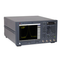
Agilent Technologies E5071C ENA Option TDR Service Manual (312 pages)
Network Analyzers
Brand:
Agilent Technologies
| Category:
Network Accessory
| Size: 31.61 MB
Table of Contents
Table of Contents
7
General Information
17
Precautions
18
Software Installed
18
Organization of Service Manual
19
Instrument Covered by this Manual
21
Analyzer Options Available
22
Required Equipment
24
Power Meter Accuracy Test
28
Power Meters that Can be Tested Using this Procedure
28
Equipment Used for the Power Meter Accuracy Test
28
Description of the Test
28
Test Record for Power Meter Accuracy Test
32
Agilent Support, Services and Assistance
33
Services and Support Options
33
Contacting Agilent
33
Shipping Your Analyzer to Agilent for Service or Repair
33
Performance Test
35
Introduction
36
Test Equipment Required
37
Softkey Selection Procedure for Performance Test
37
Aux Input Test
38
Description
38
Test Equipment
38
Frequency Accuracy Test
39
Description
39
Test Equipment
39
Rf Output Level Accuracy and Flatness Test
40
Description
40
Test Equipment
40
Rf Output Level Linearity Test
41
Description
41
Test Equipment
41
Trace Noise Test
42
Description
42
Test Equipment
42
Crosstalk Test
43
Description
43
Test Equipment
43
System Dynamic Range Test
44
Description
44
Test Equipment
44
Noise Floor Test
45
Description
45
Test Equipment
45
Dynamic Accuracy Test
46
Description
46
Test Equipment
47
10. Uncorrected System Performance Test
48
Description
48
Test Equipment
48
Adjustment
49
Safety Considerations
50
Warm-Up for Adjustment
50
Required Equipment
50
Required Adjustment after Replacing Assembly
51
Writing ID
52
OCXO Adjustment
52
Frequency Reference Adjustment
53
AUX Input Adjustment
53
Synthesizer Gain Adjustment
53
Virtual Bridge Coefficient Adjustment
54
Source Output Power Adjustment
54
Receiver if Range Adjustment
54
Receiver Ports Characteristics Adjustment
55
Receiver Absolute Gain Adjustment
55
Receiver RF Range Adjustment
55
Troubleshooting
57
Introduction
58
How to Exit from the E5071C Measurement View
59
To Troubleshoot the Instrument
60
Primary Trouble Isolation
60
No Display Troubleshooting
62
Boot Process Troubleshooting
64
Troubleshooting Using Diagnostics Test
68
Power on Self Test
68
PLL Unlock
68
External Reference Signal Phase Unlock (Opt. 1E5)
68
Contents of the Diagnostics Test
68
Required Test Equipment
69
To Execute the Diagnostics Test
69
Diagnostics Test Failure Troubleshooting
72
Function Specific Troubleshooting
79
To Check the Device Driver
80
To Check the Front Panel
82
To Check the Touch Panel
82
To Check the LCD
83
To Check the External Keyboard
83
To Check the Mouse
83
To Check the Video Output
84
To Check the External Trigger Input
84
To Check the GPIB
84
To Check the USB Interface Card
84
To Check the Removable Hard Disk Drive
85
Performance Test Failure Troubleshooting
86
Recommended Adjustment for Performance Test Failure
86
Performance Test Failure Troubleshooting
88
Probable Faulty Board Assembly or Parts on Adjustment Failure
94
To Configure the CPU Mother Board Assembly and BIOS
99
To Identify the Motherboard Installed
99
Testing DRAM on the Motherboard
99
To Confirm or Set the BIOS Options
100
Replaceable Parts
105
Ordering Information
106
Direct Mail Order System
106
Exchange Assemblies
107
Replaceable Parts List
108
Top View (Major Assemblies)
108
Top View up to 8.5 Ghz Options (Cables)
110
Top View over 8.5 Ghz Options (Cables)
112
Top View (Miscellaneous Parts)
114
Top View up to 8.5 Ghz Options (under Power Supply)
116
Top View up to 8.5 Ghz Options (Motherboard and Other Parts)
117
Bottom View
119
Front View up to 8.5 Ghz Options (Analog)
121
Front View over 8.5 Ghz Options (Analog)
122
Front View over 8.5 Ghz Options (Miscellaneous Parts)
123
Front View (Semirigid Cables) (up to 8.5 Ghz Options)
124
Front View (Semirigid Cables) (up to 8.5 Ghz Options)
125
Front View (Semirigid Cables) (over 8.5 Ghz Options - 2 Port)
126
Front View (Semirigid Cables) (over 8.5 Ghz Options - 4 Port)
127
Front Panel
128
Rear View (1)
131
Rear View (2)
132
Cover Assembly
133
Left Side View
134
Right Side View
135
Removable Hard Disk Drive Assembly (Obsolete)
136
Removable Hard Disk Drive Assembly Option 017
137
Hard Disk Drive Assembly Option 019
139
PCI DSP Card, GPIB Card and USB Card Assembly
141
PCA Digital Board Assembly
142
T2 Switch (up to 8.5 Ghz Options) Assembly
143
Receiver Module (over 8.5 Ghz Options) Assembly
144
Attenuator (over 8.5 Ghz Options) Assembly
145
Fan Assembly
146
Power Supply (up to 8.5 Ghz Options) Assembly
147
Power Supply (over 8.5 Ghz Options)Assembly
148
PCA DC Bias and Oven Assembly
149
Analog Motherboard Assembly
150
Chassis Assembly
151
Keyboard Assembly
153
LCD Assembly
154
Inverter Assembly
155
Standby Switch Assembly
156
Cover (up to 8.5 Ghz Options) Assembly
157
Cover (over 8.5 Ghz Options) Assembly
158
Label on Front Face
159
Label on Rear Face
160
Other Parts
162
Replacement Procedure
163
Replacing an Assembly
164
Required Tools
165
Outer Cover Removal
167
Tools Required
167
Procedure
167
Front Panel Removal
168
Tools Required
168
Procedure
168
Removable Hard Disk Assembly Removal (Obsolete)
169
Tools Required
169
Removal Procedure
169
Removable Hard Disk Drive Replacement (Obsolete)
171
Tools Required
171
Removal Procedure
171
Replacement Procedure
172
Restore Backup Files Onto the New Hard Disk Drive
173
Calibration of the Touch Screen
173
Removable Hard Disk Assembly Removal (Option 017)
175
Tools Required
175
Removal Procedure
175
Removable Hard Disk Drive Replacement Option 017
177
Tools Required
177
Removal Procedure
177
Replacement Procedure
178
Hard Disk Assembly Removal Option 019
179
Tools Required
179
Removal Procedure
179
Hard Disk Drive Replacement Option 019
180
Tools Required
180
Removal Procedure
180
Replacement Procedure
182
Power Supply Assembly Replacement
183
Tools Required
183
Removal Procedure
183
Replacement Procedure
184
Power Supply Assembly (over 8.5 Ghz Options) Replacement
185
Tools Required
185
Removal Procedure
185
Replacement Procedure
186
Digital Bridge Board Replacement (A53)
187
Tools Required
187
Removal Procedure
187
Replacement Procedure
188
Handler I/O Board Replacement (A25)
189
Tools Required
189
Removal Procedure
189
Replacement Procedure
190
USB (USBTMC) Interface Card Replacement
191
Tools Required
191
Removal Procedure
191
Replacement Procedure
192
PCI DSP Card and GPIB Card Replacement (A51)
193
Tools Required
193
Removal Procedure
193
Replacement Procedure
194
Digital Motherboard Replacement (A01)
195
Tools Required
195
Removal Procedure
195
Replacement Procedure
196
Analog Base Module Replacement (A0)
197
Tools Required
197
Removal Procedure
197
Replacement Procedure
198
Level Vernier Module Replacement (A3)
199
Tools Required
199
Removal Procedure
199
Replacement Procedure
200
Doubler Module Replacement (A6)
201
Tools Required
201
Removal Procedure
201
Replacement Procedure
202
Synthesizer Module Replacement (A1)
203
Tools Required
203
Removal Procedure
203
Replacement Procedure
204
Receiver Module Replacement for 2-Port Model (A2/A7+A9)
205
Up to 8.5 Ghz (A2)
205
Over 8.5 Ghz Options (A7&A9)
207
Receiver Module Replacement for 4-Port Model (A82/A87)
210
Up to 8.5 Ghz Options (A2)
210
Over 8.5 Ghz Options (A7&A9)
212
RF Switch and Distributor Module Replacement for 2-Port Model (A84)
215
Tools Required
215
Removal Procedure
215
Replacement Procedure
216
RF Switch and Distributor Module Replacement for 4-Port Model (T2-SW and A4)
217
Tools Required
217
Removal Procedure
217
Replacement Procedure
218
IMIX, Attenuator and Distributor Module Replacement (IMX, ATT and A4)
219
2-Ports Options
219
4-Ports Options
221
Fan Replacement
224
Tools Required
224
Removal Procedure
224
Replacement Procedure
225
PCA DC Bias Board (Opt.xx5) Replacement (A57/A58)
226
Tools Required
226
Removal Procedure
226
Replacement Procedure
226
10 Mhz Oven Board (Opt. 1E5) Replacement (A5)
227
Tools Required
227
Removal Procedure
227
Replacement Procedure
227
Analog Motherboard Replacement (A50)
228
Tools Required
228
Removal Procedure
228
Replacement Procedure
229
Front Panel Cover Removal
230
Tools Required
230
Removal Procedure
230
Control Touch Panel Replacement
231
Tools Required
231
Removal Procedure
231
Replacement Procedure
231
Inverter Board Replacement
232
Tools Required
232
Removal Procedure
232
Replacement Procedure
233
LCD Replacement
234
Tools Required
234
Removal Procedure
234
Replacement Procedure
235
Front Panel Keyboard Replacement
236
Tools Required
236
Removal Procedure
236
Replacement Procedure
237
Front USB Board Replacement (A55)
238
Tools Required
238
Removal Procedure
238
Replacement Procedure
239
Probe Power and Power Switch Board Replacement (A56)
240
Tools Required
240
Removal Procedure
240
Replacement Procedure
241
Post-Repair Procedures
243
Manual Changes
253
Manual Changes
254
System Recovery
255
System Recovery
256
Types of System Recoveries
256
Notes on Executing the Factory Recovery Function
257
Procedure to Execute the Factory Recovery (HDD Revision: CN925 or Above)
258
Procedure to Execute the Factory Recovery (HDD Revision: CN924 or Below)
260
Procedure to Create the User Backup Image (HDD Revision: CN924 or Below)
262
Procedure to Execute the User Recovery Function (HDD Revision: CN924 or Below)
268
Initial Registration of E5071C
279
Initial Registration Procedure (HDD Revision: CN925 or Above)
279
Initial Registration Procedure (HDD Revision: CN924 or Below)
283
Calibration of the Touch Screen
285
Firmware Update
287
Firmware Update
288
Required Equipment
288
Location of the Latest E5071C Firmware
288
How to Update the E5071C Firmware
288
Power Requirement
291
Preparation for Power Supply
292
Power Requirements
292
Verification and Connection of Power Cable
292
Blown Fuses
292
Turning the Power on and off
293
Turning the Power on
293
Turning the Power off
293
Messages
295
Error Messages
297
Warning Message
310
Advertisement
Agilent Technologies E5071C ENA Option TDR Compliance Tests (45 pages)
ESA DisplayPort PHY Compliance test Standard Version 1 Revision 2b Agilent Method of Implementation (MOI) for DisplayPort Cable Compliance Tests
Brand:
Agilent Technologies
| Category:
Software
| Size: 1.36 MB
Table of Contents
Table of Contents
2
1 Modification Record
4
2 Purpose
4
3 References
4
4 Resource Requirements
4
5 Test Procedure
5
Outline of Test Procedure
5
Instrument Setup
6
Connection Configuration
7
Calibration
10
Time Domain Calibration
10
Frequency Domain Calibration
14
Set System Impedance (Optional)
16
Measurement and Data Analysis
17
Bulk Cable and Connector Impedance
17
Intra-Pair Skew
18
Insertion Loss
19
Return Loss
20
Inter- Pair Skew
21
Near End Noise (NEN)
22
Far End Noise (FEN)
23
6 Appendix
28
Defining a Calibration Kit
28
Manual Setup for Time Domain Measurement
31
Starting Setup
31
Bulk Cable and Connector Impedance Measurements (Normative)
32
Intra-Pair Skew Measurement (Normative)
33
Inter-Pair Skew Measurements (Normative)
35
Manual Setup for Frequency Domain Measurement
35
Channel and Trace Settings
35
Common Settings
36
Far End Noise (FEN) Measurement (Normative)
36
Return Loss Measurement (Normative)
37
Insertion Loss Measurement (Normative)
37
Near End Noise (NEN) Measurement
37
Limit Test Settings
38
Displaying Judgment Result of Test
38
Setting the Warning Beeper
38
Defining the Limit Line
38
Calculating Formula for Limit Line
39
Bulk Cable and Connector Impedance
39
Insertion Loss
41
Return Loss
42
Near End Noise (NEN)
44
Far End Noise (FEN)
44
Advertisement
Related Products
Agilent Technologies E5071C
Agilent Technologies E5071B ENA Series
Agilent Technologies E5071B
Agilent Technologies E5071A
Agilent Technologies E5071C ENA Series
Agilent E5071BU
Agilent Technologies E5071A ENA Series
Agilent Technologies E5071CU 028
Agilent Technologies E5070
Agilent Technologies E5070A ENA Series
Agilent Technologies Categories
Measuring Instruments
Laboratory Equipment
Test Equipment
Water Pump
Power Supply
More Agilent Technologies Manuals
Login
Sign In
OR
Sign in with Facebook
Sign in with Google
Upload manual
Upload from disk
Upload from URL