
Related Manuals for Acer Z5700 Series


Summary of Contents for Acer Z5700 Series
- Page 1 Aspire Z5700/Z5710 Series Service Guide Service guide files and updates are available on the ACER/CSD web; for more information, please refer to http://csd.acer.com.tw PRINTED IN TAIWAN...
-
Page 2: Revision History
Revision History Please refer to the table below for the updates made on this service guide. Date Chapter Updates... - Page 3 Copyright Copyright © 2010 by Acer Incorporated. All rights reserved. No part of this publication may be reproduced, transmitted, transcribed, stored in a retrieval system, or translated into any language or computer language, in any form or by any means, electronic, mechanical, magnetic, optical, chemical, manual or otherwise, without the prior written permission of Acer Incorporated.
-
Page 4: Conventions
Conventions The following conventions are used in this manual: SCREEN MESSAGES NOTE WARNING CAUTION IMPORTANT NOTE: This symbol where placed in the Service Guide designates a component that should be recycled according to the local regulations. Denotes actual messages that appear on screen. - Page 5 Preface Before using this information and the product it supports, please read the following general information. This Service Guide provides you with all technical information relating to the BASIC CONFIGURATION decided for Acer's "global" product offering. To better fit local market requirements and enhance product competitiveness, your regional office MAY have decided to extend the functionality of a machine (e.g.
-
Page 7: Table Of Contents
System Specifications Features ............1 System Block Diagram . - Page 8 Table of Contents Removing the Thermal Module ........81 Removing the Fans .
- Page 9 Jumper and Connector Locations Mainboard Top View ..........175 BIOS Recovery .
- Page 10 Table of Contents...
-
Page 11: System Specifications
Intel® Core™ i5-750 processor (8 MB L3 cache, 2.66 GHz with Turbo Boost up to 3.20 GHz, DDR3 1333 MHz, 95 W), supporting Intel® EM64T Technology, Intel® Virtualization Technology Z5700/Z5710 • Intel® Core™ i5-650/i5-660/i5-670 processor (4 MB L3 cache, 3.20/3.33/3.46 GHz, DDR3 1333 MHz, 73 W), supporting Intel®... -
Page 12: Hard Drive
• WMV9 (VC-1), H.264 (AVC), DivX® decoding • HDMI™ (High-Definition Multimedia Interface) with HDCP (High-bandwidth Digital Content Protection) support Z5700 • Intel® HD Graphics with 1.70 GB of video memory, featuring: • Intel® Clear Video HD Technology, DVD upscaling •... -
Page 13: Optical Drive
Optical drive 4X Blu-ray Disc™ Reader / DVD-Super Multi double-layer drive: • Read: 48X CD-ROM, 48X CD-R, 48 CD-RW, 16X DVD-ROM, 16X DVD-R, 16X DVD+R, 8X DVD- ROM DL, 8X DVD-R DL, 8X DVD+R DL, 8X DVD-RW, 8X DVD+RW, 12X DVD-RAM, 6X BD- ROM, 6X BD-R, 2X BD-RE, 6X BD-ROM DL, 2X BD-R DL, 2X BD-RE DL •... -
Page 14: Power Supply Unit
Communication • WLAN: • 802.11 b/g Wi-Fi CERTIFIED™ • 802.11 b/g/n Wi-Fi CERTIFIED™ • WPAN: • Bluetooth® 2.1 + EDR • LAN: • Gigabit Ethernet • Built-in 1 MP high-def webcam with 1280 x 800 resolution image capture • Built-in microphone I/O ports Side: •... -
Page 15: Dimensions And Weight
Software • Productivity: • Acer Touch Suite • Adobe® Reader® • eSobi™ • Microsoft® Office 2007 Trial with Microsoft® Works • Microsoft® Touch Pack (Microsoft® Surface Globe/Microsoft® Surface Collage/Microsoft® Surface Lagoon/Microsoft® Blackboard/Microsoft® Rebound/ Microsoft® Garden Pond) • Multimedia: • CyberLink® PowerCinema® •... -
Page 16: System Block Diagram
System Block Diagram MXM CNN (Graphics) Mobile PCI-E Module TYPE-A(or B) (285 pin) (Max 45W) LVDS LCD Panel CNN Samsung LTM230TT01 (23'' 16:10) (34.5W) Inverter CONN LVDS LVDS Transmitter 14.318MHz Chrontel CH7308 LQFP64 ACIN SATA HDD(3.5") P3P3V_DUAL P5V_STBY SATA ODD DDRIII Power VCC5 eSATA... -
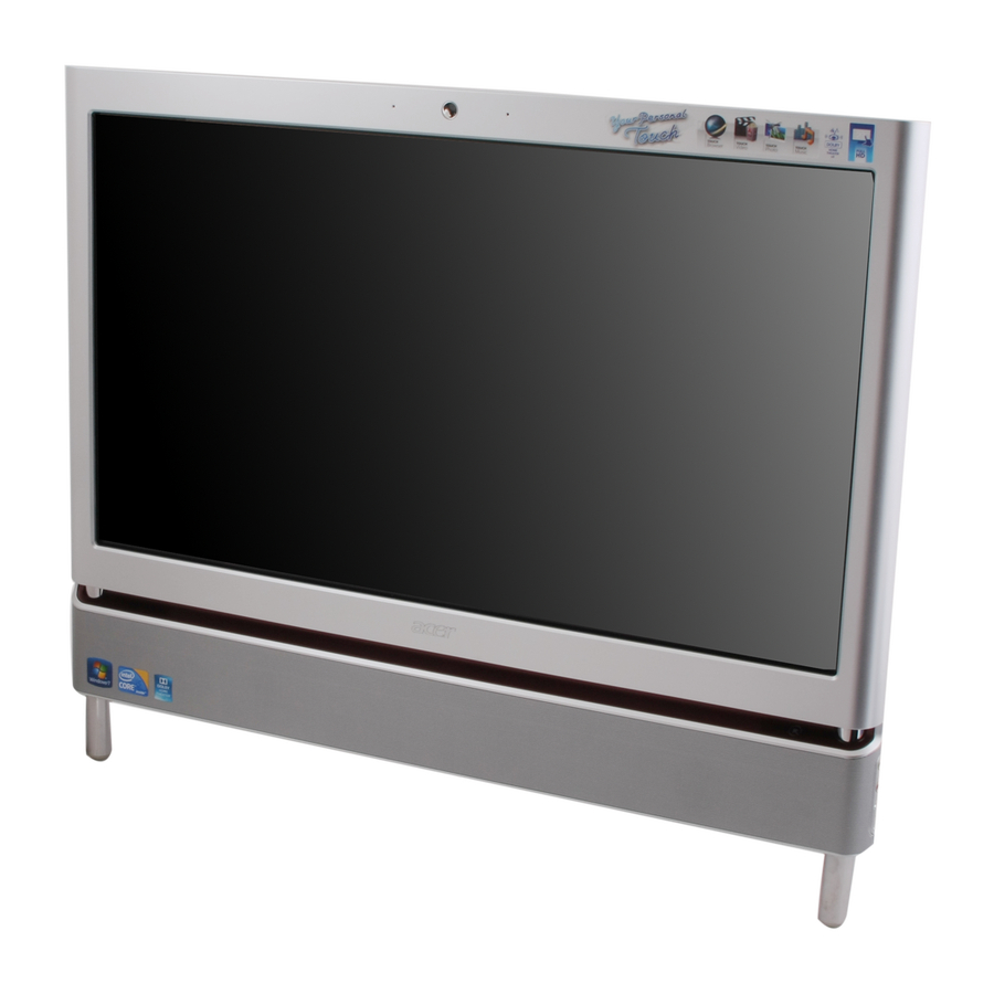
Page 17: Your Computer Tour
Your Computer tour This section describes port locations, indicators, and controls for the computer. IMPORTANT:Your computer’s hardware options, port locations, and indicators may vary from this illustration. Front View Component Microphone HD webcam Display screen Acer TouchPortal Power Button Chapter 1 Icon Description Use to talk through when making Voice over... -
Page 18: Right View
Right View IMPORTANT:Your computer’s hardware options, port locations, and indicators may vary from this illustration. Component Headphone jack (white plug) Microphone jack (pink plug) Illumination Toggle Switch Memory card reader Optical Disk Drive Icon Plug powered, analog front speakers, an external amplifier, or headphones into this jack. -
Page 19: Left View
Left View IMPORTANT:Your computer’s hardware options, port locations, and indicators may vary from this illustration. Component B-CAS reader USB 2.0 port Chapter 1 Icon Subscription service available for select models only. Plug USB (Universal Serial Bus) devices (such as a USB external drive, printer, scanner, camera, keyboard, or mouse) into this port. -
Page 20: Rear View
Rear View IMPORTANT:Your computer’s hardware options, port locations, and indicators may vary from this illustration. Component Power connector Kensington™ lock slot USB ports Ethernet (network) jack Line-out/Speaker- out jack eSATA port TV Tuner IR port Icon Plug the power cord into this connector. Secure your computer to an object by connecting a Kensington cable lock to this slot. -
Page 21: Using The Keyboard
Using the Keyboard The keyboard has several different types of keys and buttons as shown below. Fn key Windows key Feature Function keys Audio playback keys Windows key Fn key Application key Navigation keys Chapter 1 Function keys Audio playback keys Application Icon Press these keys to start program actions. -
Page 22: Windows Keys
Windows Keys The keyboard has two keys that perform Windows-specific functions. Windows key Pressed alone, this key has the same effect as clicking on the Windows Start button; it launches the Start menu. It can also be used with other keys to provide a variety of functions: <... -
Page 23: Hardware Specifications And Configurations
Hardware Specifications and Configurations Processor Item CPU type* • • • *Dependent on model shipped. Chipset Item Core logic Ibex Peak package H57 • FCBGA package • Package size: 27mm x 27mm • Ball Count: 951 • Ball pitch: 0.7mm Features •... - Page 24 Processor Specifications Processor Cores Speed i3 530 2.93G i3 540 3.06G i5 650 3.2G i5 660 3.33G i5 661 3.33G i5 670 3.46G i5 750 2.66G i7 860 2.8G i7 870 2.93G BIOS Item BIOS vendor BIOS Version BIOS ROM type Features System Memory Item...
- Page 25 Memory Combinations Slot 1 1024MB 1024MB 1024MB 1024MB 2048MB 2048MB 2048MB 2048MB 4096MB Above table lists some system memory configurations. You may combine DIMMs with various capacities to form other combinations. On above table, the configuration of slot 1 and slot 2 could be reversed. USB Port Item Chipset...
- Page 26 Hard Disk Drive Interface Item Vendor & Model Name Capacity (GB) Bytes per sector Data heads Drive Format Disks Spindle speed (RPM) Performance Specifications Buffer size Interface Internal transfer rate (MB/ sec, max) I/O data transfer rate (Mbytes/sec max) DC Power Requirements Voltage Hard Disk Drive Interface (continued) Item...
- Page 27 Hard Disk Drive Interface (continued) Item Vendor & Model Name Capacity (GB) Bytes per sector Data heads Drive Format Disks Spindle speed (RPM) Performance Specifications Buffer size Interface Internal transfer rate (MB/ sec) I/O data transfer rate (Mbytes/sec max) DC Power Requirements Voltage Video Interface Item...
- Page 28 Keyboard Controller Item Controller Total number of keypads Windows logo key Hotkeys Bluetooth Item Chipset Data throughput Protocol Connector type TV Tuner Item TV Tuner • ATSC/QAM/HRC/IRC/Standard Cable • DVB-T • ISDB-T • DMB-T/H • Meets Microsoft Media Center TV Tuner requirements VGA Controller Item •...
- Page 29 LCD 23” Item Vendor/model name Screen Diagonal (mm) Active Area (mm) Display resolution (pixels) Pixel Pitch Display Mode Typical White Luminance (cd/ ) also called Brightness Supported Colors Contrast Ratio Response Time (Optical Rise Time/Fall Time) msec Nominal Input Voltage VDD Interface Viewing Angle (degree) Horizontal:...
- Page 30 Resolution 1366x768 1400x900 1400x1050 1600x900 1600x1024 1680x1050 1920x1080 Power Supply Item AC Input • Auto ranging from 100V to 240V and 50Hz to 60Hz DC Output • 5V, 40W; 3.3V, 19.8W; 12V, 174W; 12V, 6W, 5VSB, 10W • Uses 3 prong ICE-320-C13 or IEC-320-C5 connector for AC power •...
- Page 31 System Power Management Item Mech. Off (G3) Working (G0/S0) Suspend to RAM (S3) Save to Disk (S4) Chapter 1 Specification Al devices in the system are turned off completely. Individual devices such as the CPU and hard disc may be power managed in this state.
- Page 32 Chapter 1...
-
Page 33: System Utilities
System Utilities BIOS Setup Utility The BIOS Setup Utility is a hardware configuration program built into your computer’s BIOS (Basic Input/ Output System). Your computer is already properly configured and optimized, and you do not need to run this utility. However, if you encounter configuration problems, you may need to run Setup. -
Page 34: Cmos Setup Utility
CMOS Setup Utility The CMOS Setup Utility screen displays a list of the functions and features available in the BIOS. C M O S S e t u p U t i l i t y - C o p y r i g h t ( C ) 1 9 8 5 - 2 0 1 0 , A m e r i c a n M e g a t r e n d s I n c . ... -
Page 35: Product Information
Product Information The Product Information screen displays a summary of the computer hardware information. C M O S S e t u p U t i l i t y - C o p y r i g h t ( C ) 1 9 8 5 - 2 0 1 0 , A m e r i c a n M e g a t r e n d s I n c . P r o d u c t I n f o r m a t i o n O v e r v i e w P r o c e s s o r Ty p e I n t e l ( R ) C o r e ( T M ) i 7 C P U... -
Page 36: Standard Cmos Features
Standard CMOS Features The Standard CMOS Features screen allows the user to set the system time and date as well as set HDD and ODD options. C M O S S e t u p U t i l i t y - C o p y r i g h t ( C ) 1 9 8 5 - 2 0 1 0 , A m e r i c a n M e g a t r e n d s I n c . S y s t e m D a t e S y s t e m Ti m e ... -
Page 37: Advanced Bios Features
Advanced BIOS Features The Advanced BIOS Features screen allows configuration of the various advanced BIOS options. C M O S S e t u p U t i l i t y - C o p y r i g h t ( C ) 1 9 8 5 - 2 0 1 0 , A m e r i c a n M e g a t r e n d s I n c . Q u i c k B o o t Q u i e t B o o t 1 s t B o o t D e v i c e... -
Page 38: Advanced Chipset Features
Advanced Chipset Features The Advanced Chipset Features screens. C M O S S e t u p U t i l i t y - C o p y r i g h t ( C ) 1 9 8 5 - 2 0 1 0 , A m e r i c a n M e g a t r e n d s I n c . I n t e l E I S T I n t e l ( R ) R u r b o M o d e t e c h I n t e l X D B i t... -
Page 39: Integrated Peripherals
Integrated Peripherals The Integrated Peripherals screen contains parameters for device peripherals. C M O S S e t u p U t i l i t y - C o p y r i g h t ( C ) 1 9 8 5 - 2 0 1 0 , A m e r i c a n M e g a t r e n d s I n c . O n b o a r d S ATA C o n t r o l l e r O n b o a r d S ATA M o d e O n b o a r d U S B C o n t r o l l e r... -
Page 40: Power Management Features
Power Management Features The Power Management Features screen contains parameters used for device power management. C M O S S e t u p U t i l i t y - C o p y r i g h t ( C ) 1 9 8 5 - 2 0 1 0 , A m e r i c a n M e g a t r e n d s I n c . A C P I S u s p e n d M o d e P o w e r O n b y RT C A l a r m P o w e r O n b y O n b o a r d L A N... -
Page 41: Pc Health
PC Health The PC Health screen displays CPU/Chipset temperature information and contains customizable safety monitors for the CPU. C M O S S e t u p U t i l i t y - C o p y r i g h t ( C ) 1 9 8 5 - 2 0 1 0 , A m e r i c a n M e g a t r e n d s I n c . C P U Te m p e r a t u r e ( P E C I M o d e ) C P U F a n 1 S p e e d C P U F a n 2 S p e e d... -
Page 42: Frequency Voltage Control
Frequency Voltage Control The Frequency Voltage Control Screen to set memory and processor parameters. C M O S S e t u p U t i l i t y - C o p y r i g h t ( C ) 1 9 8 5 - 2 0 1 0 , A m e r i c a n M e g a t r e n d s I n c . E n a b l e C l o c k t o A l l P C E I S p r e a d S p e c t r u m : M o v e... -
Page 43: Bios Security Features
BIOS Security Features The BIOS Security Features screen contains parameters that help safeguard and protect your computer from unauthorized use. C M O S S e t u p U t i l i t y - C o p y r i g h t ( C ) 1 9 8 5 - 2 0 1 0 , A m e r i c a n M e g a t r e n d s I n c . S u p e r v i s o r P a s s w o r d U s e r P a s s w o r d C h a n g e S u p e r v i s o r P a s s w o r d... -
Page 44: Setting A Password
Setting a Password Follow these steps as you set the user or the supervisor password: Use the and keys to highlight the Set Supervisor Password parameter and press the Enter key. The Set Supervisor Password box appears: E n t e r N e w P a s s w o r d C o n f i r m N e w P a s s w o r d Type a password in the “Enter New Password”... -
Page 45: Changing A Password
Changing a Password Use the and keys to highlight the Set Supervisor Password parameter and press the Enter key. The Set Password box appears. E n t e r C u r r e n t P a s s w o r d E n t e r N e w P a s s w o r d C o n f i r m N e w P a s s w o r d Type the current password in the Enter Current Password field and press Enter. -
Page 46: Bios Flash Utilities
BIOS Flash Utilities The BIOS flash memory update is required for the following conditions: • New versions of system programs • New features or options • Restore BIOS when it becomes corrupted. This section contains instructions for the following BIOS utilities: •... -
Page 47: Dos Flash Utility
DOS Flash Utility Perform the following steps to use the DOS Flash Utility: Copy the flash utilities to the bootable device. Attach the device to the system and restart. Press F2 during boot to enter the Setup Menu. Select Boot Menu to modify the boot priority order, for example, if using USB HDD to Update BIOS, move USB HDD to position 1. -
Page 48: Win Flash Utility
Win Flash Utility Perform the following steps to use the WinFlash Utility: Open the Start menu and type CMD to open command mode. Type “fbbwin64” to flash BIOS. The process will start automatically. IMPORTANT:During the flash process the keyboard and mouse will not function. Once the flash process has finished, shutdown the system and press the power button to restart. -
Page 49: Using Dmi Tools
Using DMI Tools Use QDMI30A to change the asset tag, product name, or serial number of the machine. Copy the file qdmi30a.exe to USB flash disk with bootable diskette or USB drive. Press F2 during boot to enter the Setup Menu. Select Boot Menu to modify the boot priority order, for example, if using a USB HDD to run DMI Tools, move USB HDD to position 1. -
Page 50: Machine Disassembly And Replacement
Machine Disassembly and Replacement WARNING:This computer has two highly sensitive touchscreen sensors on the top left and right corners of the LCD. The sensors are an integral part of the LCD and cannot be separately replaced. The sensors are exposed as soon as the rear cover is removed. During disassembly: DO NOT make contact with the sensors. - Page 51 Screw M2.5*5.0-I(BNI)(NYLOK)IRON M3*4-I(NI)(NYLOK)IRON 6-32UNC*5-B(NYLOK)IRON M2.0*2.5-I (BNI,NYLOK)IRON M2.0*3.0-I-NI-NYLOK IRON Quantity Part Number 86.G8507.005 86.G8507.006 86.G8507.007 86.G8507.008 86.G8507.009 Chapter 3...
-
Page 52: Disassembly Process
Disassembly Process Disassembly Flowchart Remove Remove HDD Module Audio Board Remove Inverter Board Remove Remove WLAN Board Remove Remove Antennas Speakers Remove Bluetooth Module Chapter 3 Turn off power and disconnect all cables before proceeding Remove Remove Stand Assembly ODD Bezel Remove Rear Cover Remove... - Page 53 Screw List Step Stand Cover Stand Hinge Rear Cover Audio Board HDD Bracket ODD Brackets Inverter Board Touchscreen Control Board Mainboard Shielding WLAN TV Tuner Module VGA Card Mainboard USB Board IR Receiver Frame LCD Panel Power Board Camera Antennas Speakers Screw M2.5*4...
-
Page 54: Removing The Ram Covers
Removing the RAM Covers 1. See “Pre-disassembly Instructions” on page 40. 2. Apply pressure to one end of the RAM Cover, while pulling up with the opposite hand as shown. 3. Lift the RAM Cover clear of the device. 4. Grasp the Hinge Cover with both hands. Chapter 3... - Page 55 5. Lift the Hinge Cover clear of the device. Chapter 3...
-
Page 56: Removing The Ram
Removing the RAM 1. See “Removing the RAM Covers” on page 44 2. Lift the RAM Shielding clear of the device. 3. Unlock the latches on either side of the RAM by pressing down as shown. There is an audible click when the latch is unlocked. -
Page 57: Removing The Rear Covers
Removing the Rear Covers 1. See “Removing the RAM” on page 46 2. Remove the six (6) screws that secure the Rear Covers. Step Rear Covers M2.5*6.0 3. Use both hands to gently push the rear cover outward from the device as shown. 4. -
Page 58: Removing The Back Cover
Removing the Back Cover 1. See “Removing the Touchscreen Control Board” on page 59 2. Remove the fourteen (14) screws securing the Back Cover. Step Back Cover 2.5*8 2.4*8 3. Use both hands to move the Hinge up into the stand position. There is an audible click when the Hinge is locked in position. - Page 59 4. Place one hand firmly on the Back Cover. Use the opposite hand to pry the Bezel away, working from one corner to the other as shown. Repeat this step until all guides along the bottom of the device are unlocked. 5.
-
Page 60: Removing The Hinge
Removing the Hinge 1. See “Removing the Back Cover” on page 48 2. Replace the Hinge to the carry position. 3. Remove the six (6) screws securing the Hinge. Step Hinge M4*8 4. Lift the Hinge clear of the device. Chapter 3 Size Quantity... -
Page 61: Removing The Mainboard Shielding
Removing the Mainboard Shielding 1. See “Removing the Audio Board” on page 63. 2. See “Removing the Touchscreen Control Board” on page 59. 3. Remove the one (1) screw from the ground wire. Step HDD Ground M2.5*4 Cable 4. Remove the small power cable from the mainboard. Size Quantity Screw Type... - Page 62 5. Detach the power cable from the mainboard. 6. Remove the adhesive tape holding the HDD ground cable to the HDD. 7. Remove the one (1) screw from the ground wire. Step Converter M2.5*4 Ground Cable Chapter 3 Size Quantity Screw Type...
- Page 63 8. Disconnect the HDD cable. 9. Remove the power cable from the HDD. 10. Remove the six (6) screws. Step Mainboard M2.5*4Ni Shielding Size Quantity Screw Type Chapter 3...
- Page 64 11. Lift the mainboard shielding away from the chassis. Chapter 3...
-
Page 65: Removing The Hard Disk Drive
Removing the Hard Disk Drive 1. See “Removing the Back Cover” on page 48. 2. Disconnect the HDD cable. 3. Remove the two (2) screws. Step M2.5*4 Size Quantity Screw Type Chapter 3... - Page 66 4. Slide the HDD towards the speakers to release it from the flanges. 5. Lift the HDD out of the chassis. 6. Remove the four (4) screws from the HDD bracket (both sides). Step Size Quantity Screw Type HD Bracket M3*4 Chapter 3...
- Page 67 7. Remove the brackets from the HDD. Chapter 3...
-
Page 68: Removing The Power Supply
Removing the Power Supply 1. See “Removing the Hinge” on page 50 2. Remove two (2) screws securing the Power Supply as shown. Step Power Supply M2.5*4 3. Lift the Power Supply clear of the device. Chapter 3 Size Quantity Screw Type... -
Page 69: Removing The Touchscreen Control Board
Removing the Touchscreen Control Board 1. See “Removing the Back Cover” on page 48 2. Remove the one (1) ground cable screw. Step Touchscreen M2.5*4 Control Board 3. Disconnect the right (top in this image) touch sensor cable. Size Quantity Screw Type Chapter 3... - Page 70 4. Disconnect the left (bottom in this image) touch sensor cable. 5. Disconnect the touchscreen board to mainboard cable. 6. Remove the two (2) screws. Step Size Quantity Screw Type Touchscreen Board M2.0*4 Chapter 3...
- Page 71 7. Lift the touchscreen board away. Chapter 3...
-
Page 72: Removing The Card Reader Board
Removing the Card Reader Board 1. Disconnect the Card reader cable. 2. Remove the two (2) screws. Step Card Reader Board 2.5*4 3. Lift the card reader board away. Chapter 3 Size Quantity Screw Type... -
Page 73: Removing The Audio Board
Removing the Audio Board 1. See “Removing the Back Cover” on page 48. 2. Disconnect the Audio board cable. 3. Remove the two (2) screws from the audio board. Step Audio Board M2.5*4 Size Quantity Screw Type Chapter 3... - Page 74 4. Lift the audio board and cable away at an angle from the rear cover. Chapter 3...
-
Page 75: Removing The Odd Eject Board
Removing the ODD Eject Board 1. See “Removing the Back Cover” on page 48 2. Disconnect the ODD Eject Board Cable. 3. Remove the one (1) screw from the ODD eject board. Step Audio Board M2.5*4 Size Quantity Screw Type Chapter 3... - Page 76 4. Remove the ODD Eject Board. Chapter 3...
-
Page 77: Removing The Odd
Removing the ODD 1. See “Removing the Back Cover” on page 48. 2. Remove the two (2) screws. Step M2.5*4 3. Slide the ODD assembly out. Size Quantity Screw Type Chapter 3... - Page 78 4. Lift the ODD away from the chassis. 5. Remove the two (2) screws from the side bracket and remove the bracket. Step Size Quantity Screw Type ODD Side Bracket M2*2.5 Chapter 3...
- Page 79 6. Remove the two (2) screws from the ODD rear bracket and remove the bracket. Step Size Quantity Screw Type ODD Rear Bracket M2*2.5 Chapter 3...
-
Page 80: Removing The Inverter Board
Removing the Inverter Board 1. See “Removing the Back Cover” on page 48. 2. Remove the adhesive covering the Inverter Board cable 1. 3. Disconnect the LCD to Inverter Board cable 1. 4. Unlock the cable clasp. Chapter 3... - Page 81 5. Disconnect the LCD to Inverter Board cable 2. 6. Disconnect the mainboard to inverter cable. 7. Remove the two (2) screws from the inverter board. Step Size Quantity Screw Type Inverter Board M2.5*3 Chapter 3...
- Page 82 8. Remove the Inverter Board. Chapter 3...
-
Page 83: Removing The Home Button Board
Removing the Home Button Board 1. See “Removing the Back Cover” on page 48 2. Disconnect the Home Button board cable. 3. Remove the one (1) screw from the Home Button Board Step Home Button M2.5*4 Board Size Quantity Screw Type Chapter 3... - Page 84 4. Remove the Home Button Board from the chassis. Chapter 3...
-
Page 85: Removing The Camera Module
Removing the Camera Module 1. See “Removing the Back Cover” on page 48 2. Remove the two (2) screws from the Camera Module Step Camera Module M2.0*3 3. Lift the Camera Module out of the chassis. Size Quantity Screw Type Chapter 3... - Page 86 4. Turn the Camera Module over. 5. Disconnect the cable from the Camera Module. Chapter 3...
-
Page 87: Removing The Tv Tuner Module
Removing the TV Tuner Module 1. See “Removing the Card Reader Board” on page 62. 2. Disconnect the TV Tuner antenna. 3. Remove the one (1) screw. Step TV Card M2.0*3 Size Quantity Screw Type Chapter 3... - Page 88 4. Lift the TV module away. Chapter 3...
-
Page 89: Removing The Wireless Lan Module
Removing the Wireless LAN Module 1. See “Removing the Card Reader Board” on page 62. 2. Disconnect the WLAN antennas. 3. Remove the one (1) screw from the WLAN module. Step WLAN M2.0*3 Size Quantity Screw Type Chapter 3... - Page 90 4. Lift the WLAN module away. Chapter 3...
-
Page 91: Removing The Thermal Module
Removing the Thermal Module 1. See “Removing the Thermal Module” on page 81. 2. Disconnect the two (2) fan cables. 3. Loosen the four (4) captive screws in numerical order (1, 2, 3, then 4). 4. Lift the thermal module away. Chapter 3... -
Page 92: Removing The Fans
Removing the Fans 1. See “Removing the Thermal Module” on page 81. 2. Remove the two (2) screws. Step 2.5*5 3. Remove the LVDS cable from the cable clips. Chapter 3 Size Quantity Screw Type... - Page 93 4. Remove the fan. 5. Remove the two (2) screws. Step Size Quantity Screw Type 2.5*5 6. Remove the fan. Chapter 3...
-
Page 94: Removing The Cpu
Removing the CPU 1. See “Removing the CPU” on page 84. 2. Unlock the CPU by pressing down on the locking latch and moving it out and away from the CPU. 3. Lift the CPU out of the package. CAUTION: Avoid any contact with a thermal pad or thermal grease. Chapter 3... -
Page 95: Removing The Mainboard
Removing the Mainboard 1. See “Removing the Card Reader Board” on page 62. 2. See “Removing the Thermal Module” on page 81. 3. See “Removing the CPU” on page 84. 4. Disconnect the sixteen (16) cables from the Mainboard as shown. Item Description LVDS Cable... - Page 96 5. Remove the adhesive tabs holding the Audio board cable to the mainboard. 6. Remove the two (2) screws. Step Size Quantity Screw Type Mainboard M2.5*4 Chapter 3...
- Page 97 7. Lift the mainboard away. NOTE: Circuit boards >10 cm² have been highlighted with a yellow rectangle as shown in the previous image. Please detach the Circuit board and follow local regulations for disposal. 8. Disconnect the IR Board cable and remove. Chapter 3...
- Page 98 9. Open cable clips as shown. Remove all cables from cable clips. NOTE: Make note of the location which cables belong in which clip before removing them. Chapter 3...
-
Page 99: Removing The Frame
Removing the Frame 1. See “Removing the Mainboard Shielding” on page 51. 2. See “Removing the Touchscreen Control Board” on page 59. 3. See “Removing the Mainboard” on page 85. 4. See “Removing the Frame” on page 89. 5. See “Removing the Frame” on page 89. 6. - Page 100 8. Unlock the LVDS cable. 9. Remove the LVDS cable. Chapter 3...
- Page 101 10. Remove the adhesive tape from the sensor cables. 11. Remove the two (2) sensor connectors. Chapter 3...
- Page 102 12. Remove the adhesive tape covering the TBD cable and remove. 13. Remove the adhesive tape covering the inverter cable. Chapter 3...
- Page 103 14. Remove the thirteen (13) screws. Step Size Quantity Screw Type Frame M2.5*4 Chapter 3...
- Page 104 15. Lift the LCD bracket clear of the bezel. WARNING:When lifting the LCD Assembly, do not touch the Touch sensor modules located at the top left and top right corners of the device. Doing so will damage the touch screen function. IMPORTANT:Do not place the LCD panel face down.
-
Page 105: Removing The Lcd Panel
Removing the LCD Panel 1. See “Removing the Frame” on page 89. 2. Remove the four (4) screws from the LCD assembly. Step LCD Panel M3*4 3. Lift the edge of the LCD bracket and pass the converter cables through. Size Quantity Screw Type... - Page 106 4. Lift the LCD bracket away from the LCD assembly. IMPORTANT:The touchscreen control board and LCD panel must be returned together for RMA purposes. See “Removing the Touchscreen Control Board” on page 59. The touchscreen control board records the specific panel’s data, do not separate these for RMA. Chapter 3...
-
Page 107: Removing The Bluetooth Module
Removing the Bluetooth Module 1. See “Removing the Bluetooth Module” on page 97. 2. Lift the Bluetooth module off of the bezel. 3. Disconnect the Bluetooth cable. Chapter 3... -
Page 108: Removing The Ir Board
Removing the IR Board 1. See “Removing the Frame” on page 89. 2. Disconnect the home button board cable. 3. Remove the one (1) screw. Step Home Board M2.5*3 Chapter 3 Size Quantity Screw Type... - Page 109 4. Remove the home button board from the bezel. Chapter 3...
-
Page 110: Removing The Home Button Board
Removing the Home Button Board 1. See “Removing the Frame” on page 89. 2. Lift the power board away from the bezel. Chapter 3... -
Page 111: Removing The Usb Board
Removing the USB Board 1. See “Removing the Back Cover” on page 48. 2. Remove the adhesive tape covering the USB cable. 3. Remove the two (2) screws. Step USB Board M2.5*4 Size Quantity Screw Type Chapter 3... - Page 112 4. Remove the USB board from the chassis. Chapter 3...
-
Page 113: Removing The Speakers
Removing the Speakers 1. See “Removing the Frame” on page 89. 2. Remove the adhesive tape from the speaker cable. 3. Remove the speaker cable from the LCD bezel. 4. Remove the adhesive tape from the speaker assembly. 5. Lift the speakers away from the bezel. Chapter 3... -
Page 114: Removing The Antennas
Removing the Antennas 1. See “Removing the Frame” on page 89. 2. Remove the two (2) screws. Step Antennas M1.7*4 3. Remove the left and right antennas from the bezel. Chapter 3 Size Quantity Screw Type... -
Page 115: Reassembly Procedure
Reassembly Procedure Replacing the Antennas 4. Replace the left and right antennas onto the bezel. 5. Replace the two (2) screws. Step Antennas M1.7*4 Size Quantity Screw Type Chapter 3... -
Page 116: Replacing The Speakers
Replacing the Speakers 1. Place the speakers onto the LCD bezel and apply the adhesive tape to secure the assembly. 2. Place the speaker cable onto the LCD bezel. 3. Place the adhesive tape to secure the speaker cable. Chapter 3... -
Page 117: Replacing The Usb Board
Replacing the USB Board 1. Place the USB board onto the LCD bezel. 2. Replace the two (2) screws. Step USB Board M2.5*4 3. Replace the adhesive tape to secure the USB cable. Size Quantity Screw Type Chapter 3... -
Page 118: Replacing The Ir Board
Replacing the IR Board 1. Place the IR board into the LCD bezel. 2. Apply pressure to set the adhesive. Chapter 3... -
Page 119: Replacing The Home Button Board
Replacing the Home Button Board 1. Place the home button board onto the LCD bezel. 2. Replace the one (1) screw. Step Home Board M2.5*3 Size Quantity Screw Type Chapter 3... -
Page 120: Replacing The Bluetooth Module
3. Connect the home button board cable. Replacing the Bluetooth Module 1. Connect the Bluetooth cable to the Bluetooth Module. 2. Adhere the Bluetooth module to the bezel. Chapter 3... -
Page 121: Replacing The Lcd Panel In The Frame
Replacing the LCD Panel in the Frame 1. Replace the LCD panel onto the frame. 2. Lower the edge of the LCD bracket and pass the converter cables through. Chapter 3... - Page 122 3. Replace the four (4) screws from the LCD assembly. Step Size Quantity Screw Type LCD Panel M3*4 Chapter 3...
-
Page 123: Replacing The Frame
Replacing the Frame 1. Place the bezel around a raised surface so that the bezel is lower than the raised surface. Lower the LCD Assembly onto the bezel. 2. Replace the thirteen (13) screws. Step Frame M2.5*4 Size Quantity Screw Type Chapter 3... - Page 124 3. Replace the adhesive tape to secure the inverter cable. 4. Replace the adhesive tape to secure the TBD cable. 5. Replace the right and left sensor connectors. Chapter 3...
- Page 125 6. Replace the adhesive tape to secure the sensor cables. NOTE: There is tape on both the top and side of the LCD bracket. 7. Connect the LVDS cable. Chapter 3...
- Page 126 8. Lock the LVDS cable. 9. Adhere the LVDS connector protective cover. 10. Replace the adhesive tape holding the LVDS cable to the LCD bracket. Chapter 3...
-
Page 127: Replacing The Mainboard
Replacing the Mainboard 1. Replace all cables into the cable clips and lock them. TBD 2. Connect the IR Board cable. Chapter 3... - Page 128 3. Place the mainboard onto the chassis. 4. Replace the two (2) screws. Step Size Quantity Screw Type Mainboard M2.5*4 5. Replace the adhesive tabs to secure the Audio board cable to the mainboard. Chapter 3...
- Page 129 6. Connect the following sixteen (16) cables to the Mainboard as shown. Item Description LVDS Cable CCD Cable Inverter Cable MIC Cable ODD Button Cable Card Reader Cable Bluetooth Cable Home Button Cable IR Cable Touch Screen Audio Cable TV Tuner Cable Light Foot Cable USB Cable Speaker Cable...
-
Page 130: Replacing The Cpu
Replacing the CPU 1. Place the CPU paying attention to the locating triangle. NOTE: Ensure the CPU is lined up with the Pin1 Socket locator on the mainboard. 2. Press the latch down and in to lock the CPU. Chapter 3... -
Page 131: Replacing The Fans
Replacing the Fans 3. Replace the right fan. 4. Replace the two (2) screws. Step 2.5*5 5. Replace the left fan. Size Quantity Screw Type Chapter 3... - Page 132 6. Place the LVDS cable into the cable clips. 7. Replace the two (2) screws. Step Size Quantity Screw Type 2.5*5 Chapter 3...
-
Page 133: Replacing The Thermal Module
Replacing the Thermal Module 1. Place the thermal module on to the mainboard. 2. Tighten the four (4) captive screws in reverse numerical order (4, 3, 2, then 1). 3. Connect the two (2) fan cables. Chapter 3... -
Page 134: Replacing The Wlan Module
Replacing the WLAN Module 1. Replace the WLAN module. 2. Replace the one (1) screw. Step WLAN M2.0*3 3. Replace the two (2) connectors. The black cable is placed closest to the DIMM slots. Chapter 3 Size Quantity Screw Type... -
Page 135: Replacing The Tv Tuner Module
Replacing the TV Tuner Module 1. Place the TV Tuner module into the connector. 2. Replace the one (1) screw. Step TV Card M2.0*3 3. Connect the TV Tuner cable. Size Quantity Screw Type Chapter 3... -
Page 136: Replacing The Camera Module
Replacing the Camera Module 1. Connect the camera cable to the Camera Module. 2. Turn the Camera Module over. 3. Place the Camera Module on to the chassis. Chapter 3... - Page 137 4. Replace the two (2) screws to secure the Camera Module Step Size Quantity Screw Type Camera Module M2.0*3 Chapter 3...
-
Page 138: Replacing The Power Board
Replacing the Power Board 1. Place the Power Board onto the chassis. 2. Replace the one (1) screw. Step Home Button M2.5*4 Board 3. Connect the Home Button board cable. Chapter 3 Size Quantity Screw Type... -
Page 139: Replacing The Inverter Board
Replacing the Inverter Board 1. Place the Inverter Board onto the chassis. 2. Replace the two (2) screws to secure the inverter board. Step Inverter Board M2.5*3 3. Connect the mainboard to inverter cable. Size Quantity Screw Type Chapter 3... - Page 140 4. Connect the LCD to Inverter Board cable 2. 5. Lock the cable clasp. 6. Connect the LCD to Inverter Board cable 1. Chapter 3...
- Page 141 7. Apply the adhesive tape to secure the Inverter Board cable 1. Chapter 3...
-
Page 142: Replacing The Odd Module
Replacing the ODD Module 1. Replace the rear ODD bracket and replace the two (2) screws. Step ODD Rear Bracket M2*2.5 2. Replace the side ODD bracket and replace the two (2) screws. Step ODD Side Bracket M2*2.5 Chapter 3 Size Quantity Size... - Page 143 3. Place the ODD onto the chassis. 4. Slide the ODD assembly into place. 5. Replace the two (2) screws. Step Size Quantity Screw Type M2.5*4 Chapter 3...
-
Page 144: Replacing The Odd Eject Board
Replacing the ODD Eject Board 1. Place the ODD Eject Board onto the chassis. 2. Replace the one (1) screw to secure the ODD eject board. Step Audio Board M2.5*4 3. Connect the ODD Eject Board Cable. Chapter 3 Size Quantity Screw Type... -
Page 145: Replacing The Audio Board
Replacing the Audio Board 1. Place the audio board onto the chassis. 2. Connect the two (2) screws to secure the audio board. Step Audio Board M2.5*4 3. Connect the Audio board cable. Size Quantity Screw Type Chapter 3... -
Page 146: Connect The Card Reader Board
Connect the Card Reader Board 1. Place the card reader board onto the chassis. 2. Replace the two (2) screws. Step Card Reader Board 2.5*4 3. Connect the Card Reader Board cable. Chapter 3 Size Quantity Screw Type... -
Page 147: Replacing The Touchscreen Board
Replacing the Touchscreen Board 1. Place the touchscreen board onto the chassis. 2. Replace the two (2) screws. Step Touchscreen M2.5*4 Control Board 3. Connect the touchscreen board to mainboard cable. Size Quantity Screw Type Chapter 3... - Page 148 4. Connect the left (bottom) touch sensor cable. 5. Connect the right (top) touch sensor cable. 6. Replace the one (1) ground cable screw. Chapter 3...
-
Page 149: Replacing The Power Supply
Replacing the Power Supply 1. Place the Power Supply onto the chassis. 2. Replace two (2) screws to secure the Power Supply as shown. Step Power Supply M2.5*4 Size Quantity Screw Type Chapter 3... -
Page 150: Replacing The Hdd
Replacing the HDD 1. Replace the HDD brackets. 2. Replace the four (4) screws to secure the HDD bracket (both sides). Step HD Bracket M3*4 3. Place the HDD on to the chassis. Chapter 3 Size Quantity Screw Type... - Page 151 4. Slide the HDD away from the speakers to secure it. 5. Replace the two (2) screws. Step Size Quantity Screw Type M2.5*4 6. Connect the HDD cable. Chapter 3...
-
Page 152: Replacing The Mainboard Shielding
Replacing the Mainboard Shielding 1. Replace the shield onto the assembly. 2. Replace the six (6) screws. Step Mainboard M2.5*4Ni Shielding Chapter 3 Size Quantity Screw Type... - Page 153 3. Connect the HDD power cable. 4. Connect the HDD cable to the mainboard. 5. Replace the one (1) screw to secure the ground wire. Step Converter M2.5*4 Ground Cable Size Quantity Screw Type Chapter 3...
- Page 154 6. Adhere the adhesive tape to secure the HDD ground cable to the HDD. 7. Connect the power cable to the mainboard. 8. Connect the TBD wire to the mainboard. Chapter 3...
- Page 155 9. Connect the one (1) screw to secure the ground wire. Step Size Quantity Screw Type HDD Ground M2.5*4 Cable Chapter 3...
-
Page 156: Replacing The Hinge
Replacing the Hinge 1. Place the Hinge onto the chassis. 2. Replace the six (6) screws to secure the Hinge. Step Hinge M4*8 Chapter 3 Size Quantity Screw Type... -
Page 157: Replacing The Rear Cover
Replacing the Rear Cover 3. Place the Back Cover on to the device. 4. Press down firmly to engage the locking clips beneath the cover. 5. Use both hands to move the Hinge to the down position. Chapter 3... - Page 158 6. Remove the fourteen (14) screws securing the Back Cover. Step Size Quantity Screw Type Back Cover 2.5*8 2.4*8 Chapter 3...
-
Page 159: Replacing The Rear Covers
Replacing the Rear Covers 1. Place the first Rear Cover onto the Back Cover and slide it into place. 2. Repeat for the second Rear Cover. Chapter 3... - Page 160 3. Replace the six (6) screws to secure the Rear Covers. Step Size Quantity Screw Type Rear Covers M2.5*6.0 Chapter 3...
-
Page 161: Replacing The Ram
Replacing the RAM 4. Place each RAM module into its slot. 5. Lock the latches on either side of the RAM by pressing inwards as shown. 6. Place the RAM Shielding onto the device. Chapter 3... -
Page 162: Replacing The Rear Covers
Replacing the Rear Covers 1. Place the Hinge Cover onto the device. 2. Apply pressure to engage the Hinge Cover latches. 3. Place the RAM Cover onto the device. Chapter 3... - Page 163 4. Slide the RAM Cover into place. Chapter 3...
-
Page 164: Troubleshooting
Troubleshooting Common Problems Use the following procedure as a guide for computer problems. NOTE: The diagnostic tests are intended to test only Acer products. Non-Acer products, prototype cards, or modified options can give false errors and invalid system responses. Obtain the failing symptoms in as much detail as possible. Verify the symptoms by attempting to re-create the failure by running the diagnostic test or by repeating the same operation. -
Page 165: Odd Failure
ODD Failure If an Optical Disk Drive failure is determined, use the following flowchart to determine the required action: DVD does not cable connection ODD Not Operating Correctly If the ODD exhibits any of the following symptoms it may be faulty: •... - Page 166 Double-click DVD/CD-ROM drives. If the device displays a down arrow, right-click on the device and click Enable. Check that there are no yellow exclamation marks against the items in lDE ATA/ATAPI controllers. If a device has an exclamation mark, right-click on the device and uninstall and reinstall the driver. Check that there are no yellow exclamation marks against the items in DVD/CD-ROM drives.
- Page 167 Click Properties and select the Advanced Settings tab. Ensure that the Enable DMA box is checked and click OK. Repeat for the other ATA Devices shown if applicable. Drive Not Detected If Windows cannot detect the drive, perform the following actions one at a time to correct the problem. Restart the computer and press F2 to enter the BIOS Utility.
-
Page 168: Wireless Failure
Wireless Failure If the wireless functionality fails, use the following flowchart to determine the required action: Chapter 4 START Wirelss function failure Check WLAN Reconnect cable connection cable correctly Check WLAN Replace module WLAN module Replace Mainboard Close Close Close... -
Page 169: Camera Failure
Camera Failure If the camera functionality fails, use the following flowchart to determine the required action: function failure Check camera cable connection Check camera START Camera Reconnect cable correctly Replace camera module module Replace Mainboard Close Close Close Chapter 4... -
Page 170: Speaker Failure
Speaker Failure If the internal speaker fails, use the following flowchart to determine the required action: cable connection Sound Problems If sound problems are experienced, perform the following actions one at a time to correct the problem. Reboot the computer. Navigate to Start... - Page 171 Restore system and file settings from a known good date using System Restore. If the issue is not fixed, repeat the preceding steps and select an earlier time and date. 10. Reinstall the Operating System. 11. If the Issue is still not resolved, see “Online Support Information” on page 192. Chapter 4...
-
Page 172: Lcd Failure
LCD Failure If the integrated LCD display fails, use the following flowchart to determine the required action: Check LCD cable connected Check LCD cable is good Check LCD module is good No POST or Video If the POST or video doesn’t display, perform the following actions one at a time to correct the problem. Make sure the computer has power by checking at least one of the following occurs: •... -
Page 173: Abnormal Video Display
Abnormal Video Display If video displays abnormally, perform the following actions one at a time to correct the problem. Reboot the computer. If permanent vertical/horizontal lines or dark spots display in the same location, the LCD is faulty and should be replaced. See “Disassembly Process” on page 42. If extensive pixel damage is present (different colored spots in the same locations on the screen), the LCD is faulty and should be replaced. -
Page 174: General Troubleshooting Issues
General Troubleshooting Issues Computer Shutsdown Intermittently If the system powers off at intervals, perform the following actions one at a time to correct the problem. Check the power cable is properly connected to the computer and the electrical outlet. Remove any extension cables between the computer and the outlet. Remove any surge protectors between the computer and the electrical outlet. -
Page 175: Hdd Not Operating Correctly
HDD Not Operating Correctly If the HDD does not operate correctly, perform the following actions one at a time to correct the problem. Disconnect all external devices. Run a complete virus scan using up-to-date software to ensure the computer is virus free. Run the Windows 7 Startup Repair Utility: insert the Windows 7 Operating System DVD in the ODD and restart the computer. - Page 176 11. Remove and reinstall the mouse driver. 12. Check the Device Manager to determine that: • The device is properly installed. There are no red Xs or yellow exclamation marks. • There are no device conflicts. • No hardware is listed under Other Devices. 13.
-
Page 177: Intermittent Problems
Intermittent Problems Intermittent system hang problems can be caused by a variety of reasons that have nothing to do with a hardware defect, such as: cosmic radiation, electrostatic discharge, or software errors. FRU replacement should be considered only when a recurring problem exists. When analyzing an intermittent problem, do the following: Run the advanced diagnostic test for the system board in loop mode at least 10 times. -
Page 178: Post Codes
POST Codes These tables describe the POST codes and descriptions during the POST. Bootblock Initialization Code Checkpoints Checkpoint Before D0 If boot block debugger is enabled, CPU cache-as-RAM functionality is enabled at this point. Stack will be enabled from this point. Early Boot Strap Processor (BSP) initialization like microcode update, frequency and other CPU critical initialization. -
Page 179: Bootblock Recovery Code Checkpoints
Bootblock Recovery Code Checkpoints Checkpoint Initialize the floppy controller in the super I/O. Some interrupt vectors are initialized. DMA controller is initialized. 8259 interrupt controller is initialized. L1 cache is enabled. Set up floppy controller and data. Attempt to read from floppy. Enable ATAPI hardware. - Page 180 Checkpoint Initializes the 8042 compatible Key Board Controller. Detects the presence of PS/2 mouse. Detects the presence of Keyboard in KBC port. Testing and initialization of different Input Devices. Also, update the Kernel Variables.Traps the INT09h vector, so that the POST INT09h handler gets control for IRQ1.
- Page 181 Checkpoint Takes care of runtime image preparation for different BIOS modules. Fill the free area in F000h segment with 0FFh. Initializes the Microsoft IRQ Routing Table. Prepares the runtime language module. Disables the system configuration display if needed. Initialize runtime language module. Display boot option popup menu. Displays the system configuration screen if enabled.
-
Page 182: Dim Code Checkpoints
DIM Code Checkpoints Checkpoint Initialize different buses and perform the following functions: Reset, Detect, and Disable (function 0); Static Device Initialization (function 1); Boot Output Device Initialization (function 2). Function 0 disables all device nodes, PCI devices, and PnP ISA cards. It also assigns PCI bus numbers. - Page 183 Number of Beeps Display memory error (system video adapter) Troubleshooting POST BIOS Beep Codes Number of Beeps 1, 3 Reseat the memory, or replace with known good modules. 6, 7 Fatal error indicating a serious problem with the system. Consult your system manufacturer.
- Page 184 Chapter 4...
-
Page 185: Jumper And Connector Locations
Jumper and Connector Locations Mainboard Top View 9 10 Item Description Iinverter conn power conn LCD conn GPU FAN conn CPU FAN conn camera conn card reader conn Bluetooth conn Home button conn IR conn Chapter 5 Item Description Audio conn light foot conn light pipe conn B-CAS conn... -
Page 186: Bios Recovery
BIOS Recovery Please save the SUPER.ROM to a USB key (Root Folder). NOTE: The USB flash should be a FAT 32 format. It does not need to be a bootable device. Connect the USB key to a USB port in the system. Press the power button to power the system up. -
Page 187: Fru (Field Replaceable Unit) List
Chapter 6 FRU (Field Replaceable Unit) List This chapter gives you the FRU (Field Replaceable Unit) listing in global configurations of this computer. Refer to this chapter whenever ordering for parts to repair or for RMA (Return Merchandise Authorization). Please note that WHEN ORDERING FRU PARTS, you should check the most up-to-date information available on your regional web or channel. -
Page 188: Exploded Diagrams
Exploded Diagrams Main Assembly EL5 FRONT BEZEL ZUB ASSY SILVER LCD(TFT)23” LTM230H01-A03 EL5LCD FRAME SUB ASSY EL5 MB (LYN)DIS W/O CPU Description 34EL5FBTN00 AA0230HT002 3SEL5LSTN00 31EL5MB0020 Acer P/N Chapter 6... - Page 189 TQ2G_3.3 CAMB_ARMB W/23” NBA230G3 ASSY EL5 CPU ASSY (INT,LYNNFIELD 2.66) STN BSQ SS(64G) MMCRE645MPP-OVA STN HDD (1TB) HDT721010SLA360 0A37993 STNBSQ EL5 BACK FRAME SUB ASSY EL5 BACK COVER SUB ASSY RED REAR COVER LEFT EL8(EBEL8001,REV3A) SILVER FRAME RAM COVER EL8 (FBEL8001,REV3A) REAR COVER RIGHT EL8(EBEL8002,REV3A) SILVER...
-
Page 190: Fru List
FRU List CATEGORY ADD ON CARD 288-1N135-000AC GEFORCE G210M 512MB (64BITS) DDR3 SAMSUNG MXM3 288-1N136-000AC GEFORCE GT240M 1GB (128BITS) DDR3 SAMSUNG MXM3 BOARD AUDIO BOARD CARD READER BOARD POWER BOARD ODD BOARD B CAS BOARD INVERTER BOARD DA-4A12-QT03L INVERTER BOARD IV40157/T-LF Lite-On WN6602RH, Ralink RT3090 WLAN Lite-On WN6602RH, Ralink RT3090, 802.11b/g/n 1x1 WLAN (mini-car QMI QBT400UB Bluetooth Qcom Technology Inc., Broadcom... - Page 191 CATEGORY POWER CORD POWER CORD 1.8M BLACK UK 3P POWER CORD 1.8M BLACK SWISS 3P POWER CORD 1.8M BLACK S.A 3P POWER CORD 1.8M BLACK UK 3P POWER CORD 1.8M BLACK IT 3P POWER CORD 1.8M BLACK INDIA 3P POWER CORD 1.8M BLACK DANISH 3P POWER CORD 1.8M BLACK AUS 3P POWER CORD 1.8M BLACK ARGENTINE 3P POWER CORD 1.8M BLACK US BSMI 3P...
- Page 192 CATEGORY INVERTER CABLE LED CABLE USB CABLE W/PORT POWER CABLE CARD READER CABLE HOME BUTTON CABLE BLUETOOTH CABLE TV TUNER CABLE TV EXTERNAL ANTENNA - DVB-T TV EXTERNAL ANTENNA - ATSC ANTENNA CASE/COVER/BRACKET ASSEMBLY FRONT COVER ASSY SILVER W/SPEAKER,H/BUTTON B,ANTENNA,USB PORT BACK COVER RED HDMI W/TV, IR, IR BLASKER, W/O B BACK COVER RED HDMI W/O TV, W/O B CAS BACK COVER RED HDMI W/TV, W/ B CAS...
- Page 193 CATEGORY HINGE COVER REAR COVER SILVER - LEFT W/O B-CAS REAR COVER SILVER - LEFT W/B CAS REAR COVER SILVER - RIGHT LCD FRAME BACK FRAME FRAME RAM COVER HINGE ODD BRACKET HDD BRACKET MXM BRACKET SPEAKER SET HEAT SINK THERMAL MODULE - UMA/DIS HEATSINK DIS FAN UMA - RIGHT...
- Page 194 CATEGORY CPU/PROCESSOR CPU Intel Core i5 750 LGA 2.66G 8M 1333 1156 95W B-1 CPU Intel Core i7 860 LGA 2.8G 8M 1333 1156 95W B-1 Quad Core CPU Intel Core i7 870 LGA 2.93G 8M 1333 1156 95W B-1 Quad Core CPU Intel Core i3 530 LGA 2.93G 4M 1333 1156 73W C-2 Dual Core...
- Page 195 CATEGORY KEYBOARD Keyboard CHICONY KG-0766 RF2.4 104KS Silver US with new color AC-MT-010 Keyboard CHICONY KG-0766 RF2.4 104KS Silver Traditional Chinese with new color AC-MT-010 Keyboard CHICONY KG-0766 RF2.4 104KS Silver Simplified Chinese with new color AC-MT-010 Keyboard CHICONY KG-0766 RF2.4 104KS Silver US International with new color AC-MT-010 Keyboard CHICONY KG-0766 RF2.4 104KS Silver Arabic/ English with new color AC-MT-010...
- Page 196 CATEGORY Keyboard CHICONY KG-0766 RF2.4 104KS Silver Russian with new color AC-MT-010 Keyboard CHICONY KG-0766 RF2.4 105KS Silver Hungarian with new color AC-MT-010 Keyboard CHICONY KG-0766 RF2.4 104KS Silver Greek with new color AC-MT-010 Keyboard CHICONY KG-0766 RF2.4 105KS Silver Danish with new color AC-MT-010 Keyboard CHICONY KG-0766 RF2.4 104KS Silver Czech with new color AC-MT-010...
- Page 197 CATEGORY MEMORY Memory SAMSUNG UNB-DIMM DDRIII 1333 1GB M378B2873EH1-CH9 LF 128*8 0.055um Memory UNIFOSA UNB-DIMM DDRIII 1333 1GB GU502203EP0201 LF 128*8 0.065um Memory SAMSUNG UNB-DIMM DDRIII 1333 2GB M378B5673EH1-CH9 LF 128*8 0.055um Memory UNIFOSA UNB-DIMM DDRIII 1333 2GB GU512303EP0202 LF 128*8 0.065um LCD PANEL W/TOUCH LCD 23 IN.
-
Page 198: Model Definition And Configuration
Appendix A Model Definition and Configuration Appendix A... - Page 199 Appendix A...
-
Page 200: Test Compatible Components
Appendix B Test Compatible Components This computer’s compatibility is tested and verified by Acer’s internal testing department. All of its system ® ® ® functions are tested under OS Linux, Windows XP Home Edition, Windows Vista, Windows 7 Home ® ®... - Page 201 Appendix B...
-
Page 202: Online Support Information
Online Support Information This section describes online technical support services available to help you repair your Acer Systems. If you are a distributor, dealer, ASP or TPM, please refer your technical queries to your local Acer branch office. Acer Branch Offices and Regional Business Units may access our website. However some information sources will require a user i.d. -
Page 203: Index
Base Assembly Removing 47 BIOS vendor 14 Version 14 – BIOS Utility Advanced 27 Exit 36 Navigating 23 PC Health 36 Power 36 Save and Exit 36 System Security 36 Board Layout Top View 175 Disassembly General Information 40 Disassembly Requirements FRU (Field Replaceable Unit) List Intermittent Problems Jumper and Connector Locations...