TRENDnet TV-IP100 User Manual
Internet camera server
Hide thumbs
Also See for TV-IP100:
- User manual (55 pages) ,
- Quick installation manual (10 pages) ,
- Datasheet (2 pages)
Table of Contents
Advertisement
Quick Links
Download this manual
See also:
User Manual
T
ABLE OF
ABOUT THIS GUIDE ............................................................3
INTRODUCTION ....................................................................4
.........................................................5
.............................................................7
.............................................................8
............................................................9
HARDWARE INSTALLATION .........................................13
SECURITY ...............................................................................15
APPLICATION OF THE CAMERA ...............................16
.........................................................................17
USING THE CAMERA ........................................................19
...............................................19
......................................................21
V
........................................................40
V
.....................................................41
IPVIEW SE ..............................................................................43
.........................................................................43
1
C
ONTENTS
...............................13
......................................14
............................................14
.............................18
Advertisement
Table of Contents

Related Manuals for TRENDnet TV-IP100


Summary of Contents for TRENDnet TV-IP100
-
Page 1: Table Of Contents
ABLE OF ONTENTS ABOUT THIS GUIDE ............3 INTRODUCTION ..............4 ............5 EATURES AND ENEFITS .............7 NPACK THE ACKAGE .............8 YSTEM EQUIREMENT ............9 HYSICAL ESCRIPTION HARDWARE INSTALLATION .........13 .......13 TTACHING THE AMERA TO THE TAND ........14 ONNECTING THE THERNET CABLE ..........14 TTACHING THE OWER UPPLY SECURITY ................15... -
Page 2: About This Guide
..............49 ETTING TARTED ............51 BOUT UIDE OW TO DD A AMERA .............57 OW TO HANGE AMERA ........58 ONNECT ISCONNECT THE MAGE ...........61 OW TO ELETE A AMERA ..............62 XTRA NFORMATION This manual provides instructions and illustrations on how to use ......63 OW TO DJUST THE... -
Page 3: Introduction
Features and Benefits Simple to Use NTRODUCTION The Internet Camera is a stand alone system with built-in CPU requiring no special hardware or software such as PC frame grabber cards. The Internet Camera supports both ActiveX mode (for Internet Explorer users) and Java mode (for Internet Explorer and Netscape Navigator users). -
Page 4: Unpack The Package
User’s Guide, be certain that you have: remote site via Intranet or Internet. When new firmware is One TV-IP100 Internet Camera available, you can also upgrade remotely over the network for One Installation CD-ROM added convenience. Users are also allowed to monitor the image, and take snapshots. -
Page 5: System Requirement
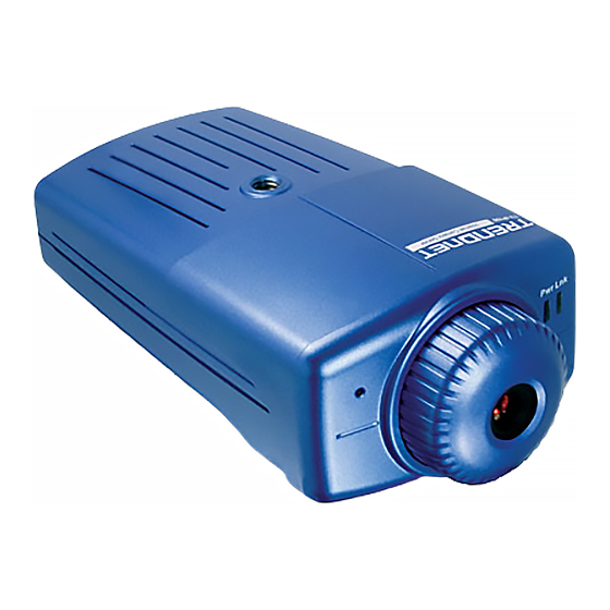
System Requirement Physical Description This section describes the externally visible features of the Networking Internet Camera. 10Base-T Ethernet or 100Base-TX Fast Ethernet. Front Panel Accessing the Camera For Web Browser Users Operating System: Microsoft® Windows® 98SE/ME/ 2000/XP CPU: Intel Pentium II, 266 MHz or above Memory Size: 32MB (64MB recommended) Resolution: 800x600 or above Microsoft®... -
Page 6: Rear Panel
2. Link LED 1. 10/100 Ethernet Port The Link LED is positioned on the right side of the Internet The Internet Camera’s rear panel features an RJ-45 connector for Camera’s lens while facing the Internet Camera. It is located connections to 10Base-T Ethernet cabling or 100Base-TX Fast right of the Power LED Ethernet cabling (which should be Category 5 twisted-pair cable). -
Page 7: Hardware Installation
Top/Bottom Panel Top Panel Screw Hole ARDWARE NSTALLATION Bottom Panel Screw Hole Attaching the Camera to the Stand The Internet Camera comes with a camera stand (optional) with a swivel ball screw head that can be attached to the Internet Camera's bottom screw hole. -
Page 8: Connecting The Ethernet Cable
Connecting the Ethernet cable Connect an Ethernet cable to the network cable connector ECURITY located Internet Camera’s rear panel, and then attach it to the network. To ensure the highest security and prevent unauthorized usage of the Internet Camera the Administrator has the exclusive privilege to access the System Administration for settings and control requirements to allow users the level of entry and authorize the privileges for all users. -
Page 9: Application Of The Camera
Applications Monitoring of local and remote places and objects such as construction sites, hospitals, amusement parks, schools and PPLICATION day-care centers through the use of a web browser. Capture single frame images from the IPView SE AMERA application. Configure the camera to upload image or send-mail messages with a single frame image. -
Page 10: Application Diagrams Of The Camera
Application Diagrams of the Camera Home or Business Applications SING THE AMERA You can access and manage the Internet Camera through: 1) a web browser, and 2) the enclosed software IPView SE. This chapter describes the Web Configuration Utility, and provides the instructions on using the camera with a web browser. -
Page 11: System Administration
System Administration Default IP address Under the Welcome screen of the Configuration Utility, click System Administration to enter the administration window that contains the settings required for the camera in the top menu bar, including Management, Configuration, Tools, Help, and Home. Pre-view area TIP: Once you have changed the settings in each option, click Save to store the settings, or Cancel to abandon, or Refresh to... - Page 12 System Click the System item in the left column to display the device status of your camera. - Video Status: The video configuration about the camera, including the Video Resolution, Compression Rate, Frame Rate, Frame Size and IP Address, can be found in this field.
- Page 13 Secondary DNS Address, Dynamic DNS, Secondary HTTP Port, and UPnP. User Click the User item in the left column to display the user(s) information. - Active Users: The items in this field display the user(s) information, including the user(s) IP address, Name, and DateTime.
- Page 14 Video Location: This field is used to enter a descriptive name for the location used by the camera (optional). Click the Video item in the left column to setup the image Admin: This field is used to enter the administrator configuration of your camera.
- Page 15 Saturation Control: Adjust the saturation with - TCP/IP: default setting at 64. IP Address Mode: This field provides your with three options to select the IP Address Mode: Light Frequency: Adjust the light frequency to suit Fixed IP – You can select this option and enter the IP your area of operation from the options either 50 Hz or address directly.
- Page 16 according to your network configuration. Select The administrator has the authority to give permission Enable from the option and enter the desired port for the privilege to control the Upload/E-mail Video number in the following box. control to the users by selecting Yes or No to activate the Upload/E-mail Video.
- Page 17 selecting this option, you have to enter the required - FTP Server: This field contains the following six basic information in the following fields: settings for your FTP server. IP Address – Enter the IP Address of the Time Server Host Address: The IP Address of the target FTP in this box.
- Page 18 Overwrite, Date/Time Suffix, and set up the Sequence between servers you need to input the mail server Number. address in this field. Sender e-mail Address: Enter the e-mail address of - Manual Operation: When you click the Upload the user who will send the e-mail. Video button in view video screen, it will start to upload Receiver e-mail Address: Enter the e-mail address of the image.
- Page 19 - Test E-mail Account: Click the Test button to test the System Administration Tools e-mail account you provided. The Tools window contains commands for restarting the camera. Click Tools in the top menu bar and the Tools window will Reset appear as below: Do you really want to reset this device? Click the YES button from this option, and you can restart the camera just like turning...
- Page 20 System Administration Help The Help window provides the basic information of the camera. Click Help in the top menu bar and the Help window will appear as below: Backup Click the Backup item in the left column to backup the current configuration.
-
Page 21: Video - Activex Mode
desired selection ON or OFF to utilize the options for each of the Video – ActiveX Mode functions. To view video images from the browser, click View Image – ActiveX Mode from the Welcome screen to access the video View Image – Java Mode images from Internet Explorer as illustrated below: Camera Name To view video images from the browser, click View Image –... -
Page 22: Ipview Se
Digital Zoom: The 4x digital zoom features will make the image even closer. In the View Video – Java Mode, you are allowed to use the Upload Video and E-mail Video options. Simply click the desired selection ON or OFF to utilize the options for each of the functions. - Page 23 To install the IPView SE application, click the "IPView SE" The Welcome screen will appear as below. Click the Next button to activate the installation procedure for the application button. program. The License Agreement window will appear as below. Read the details carefully and click the Yes button.
- Page 24 In the following window, you may click Next to accept the Please wait until one of the following two dialog boxes to appear. recommended destination location or click Browse to select If the system has to restart, select “Yes, I want to restart my another location.
-
Page 25: Getting Started
After successfully installing the IPView SE, the application Getting Started program for the Internet Camera is automatically installed to \Programs\Files directory. IPView SE is responsible for the management of preview, To start running the IPView SE, click Start > Programs > configuration, and searching of each camera. -
Page 26: How To Add A Camera
How to Add a Camera Minimize To minimize the control panel. Add Camera Exit To close IPView SE. Play To play back the recorded file. Scan To display for each camera one by one. Combine Add Camera To combine all display windows in one. About To display the information of IPView SE. - Page 27 You must select the camera and click the Add button to add a new camera. You can select the Input IP button, an Input IP dialog box will appear as illustrated below. 3. At the same time, the Gateway IP address can be replaced by URL as below: 4.
- Page 28 If you forget to highlight the camera you want to add, a dialog box will appear to notify you of the error. Make sure to save any changes you have made to keep the information updated. You must select the camera and click the Add button to add a Note : new camera.
-
Page 29: How To Change Camera
How to Change Camera Assign IP of New Camera To change camera, click the “Assign IP of Camera” button. An Assign IP of Camera dialog box will appear as illustrated below. Camera Config Motion record System Config Schedule record Assign IP to Camera Manual record Connect / Disconnect Erase Extra Information... -
Page 30: Connect/Disconnect The Image
showed. Connect/Disconnect the Image Minimize Click to minimize the display screen of the camera. Connect the Image Click the “Connect/Disconnect” button and the preview screen Maximize will appear with the video image. Click to maximize the display screen of the camera. Close Click to close the display screen of the camera. -
Page 31: How To Delete A Camera
Rotate image How to Delete a Camera Click to rotate the image of the camera. Erase Camera To delete a camera, you must select the camera to delete from the IPView SE control panel. Then, click the “Erase Camera” button. Disconnect the Image After deleting the camera, the IPView SE control panel will Click the “Connect/Disconnect”... -
Page 32: Extra Information
Extra Information How to Adjust the Property Setting System Configure Extra Information From the control panel, select the button and the dialog box will The screen displays the camera’s information. appear as shown below. Log Storage: 1. Single HDD Reserve Space This option permits reserved HDD space from 500 MB to 1000 MB. -
Page 33: Camera Setting
3. Storage List This option is used to define the path to save image files. Camera Configure The software will create a camera name folder as the Click the “Camera Config” button and it will active the Camera “Storage List” which is allowed to create up to 16 File Path. Setting, Motion Setting and Update Firmware buttons. -
Page 34: Motion Setting
Mail Server: Mail Server IP or name. Motion Setting Mail From: E-Mail Address of sender. You can adjust the sensitivity level and choose the Invoke Alarm options to work with motion detection function. Mail To: E-Mail Address of receiver. Besides the Alarm Beep, Send Email can be enabled when motion Subject: Can be any information to high light the message. -
Page 35: Adjust The Recording Setting
Adjust the Recording Setting Update Firmware Enter the File Path and click the Update button, the firmware There are three ways to start recording image - Motion Record, will be updated automatically. Schedule Record & Manual Record. Motion Record This option allows the camera to trigger recording by motion detected. -
Page 36: Appendix
Q: What algorithm is used to compress the digital image? A: The Internet Camera utilizes the JPEG image compression technology providing high quality images for users. JPEG is adopted since it is a standard for image compression and can be applied to various web browser and application software without the need to install extra software. -
Page 37: B Ping Your Ip Address
A: If a firewall exists on the network, port 80 is open for ordinary B PING Your IP Address data communication. However, since the Internet Camera transmits image data, the default port 8481 is also required. Therefore, it is necessary to open port 8481 of the network for The PING (Packet Internet Groper) command can determine remote users to access the Internet Camera. -
Page 38: C Trouble Shooting
the product by connecting a local computer to the unit, utilizing a C Trouble Shooting standard Crossover (hub to hub) Cable. If the problem is not solved the Internet Camera might be faulty. Q: I cannot access the Internet Camera from a web browser. Q: Why does the Power LED not light up constantly? A1: The possible cause might be the IP Address for the Internet A: The power supply used might be at fault. - Page 39 Q: Why does a series of broad vertical white line appears through NOTE: Applying only 16 or 256 colors on your computer will out the image? produce dithering artifacts in the image. A: A likely issue is that the CMOS sensor becomes overloaded when the light source is too bright such as direct exposure to A2: The configuration on the Internet Camera image display is sunlight or halogen light.
-
Page 40: D Time Zone Table
D Time Zone Table... -
Page 41: E Xplug Control Installation
Installation to Local PC E Xplug Control Installation Insert the CD-ROM into the CD-ROM drive to initiate the auto- Installation to Web Server run program. Once completed, a menu screen will appear as below: Important Information It is highly recommended to install the Xplug Control application to the Web Server for IE 5.0. - Page 42 Once executed, a prompt will appear requesting the input of the The License Agreement prompt will appear as below. Read the desired language selection. Make the desired selection and click details carefully and click the “Yes” button to continue with the “OK”...
-
Page 43: F Adjust Internet Camera Focus
F Adjust Internet Camera Focus G Specification Video specification To adjust the focus of the lens, you need to turn the lens slowly in Resolution: 640 x 480 pixel either clockwise or anti-clockwise direction until the desired Sensor: Color CMOS sensor image appears. -
Page 44: H Glossary Of Terms
RTOS H Glossary of Terms Power Supply: DC 5V, switching type Power consumption: 3.5 Watt (700mA x 5V) LED Indicator: Power LED (Blue) Activity LED (Orange) NUMBERS 10BASE-T is Ethernet over UTP Category III,IV, or V 10BASE-T Software unshielded twisted-pair media. Browser: Internet Explorer 5.0 or above;... - Page 45 of manually assigning it a unique IP address. DHCP allows the specification for the service provided by a router, gateway, or other network device that BOOTP Bootstrap Protocol is an Internet protocol that can automatically assigns an IP address to any device that automatically configure a network device in a diskless requests one workstation to give its own IP address.
- Page 46 system is useful because it can represent every byte (8 bits) as two consecutive hexadecimal digits. It is easier for humans to read hexadecimal numbers than binary Fast Ethernet, also called 100BASE-T, operates at 10 Fast Ethernet numbers. or 100Mbps per second over UTP, STP, or fiber-optic media.
- Page 47 IP address IP address is a 32-binary digit number that identifies each sender or receiver of information that is sent in packets across the Internet. For example 80.80.80.69 is Network Address Translator generally applied by a an IP address, it is the closet thing the Internet has to router, that makes many different IP addresses on an telephone numbers.
- Page 48 by sending a packet to the specified address and waits for a reply. It is primarily used to troubleshoot Internet connections. RARP Reverse Address Resolution Protocol, a TCP/IP protocol that allows a physical address, such as an PPPoE Point-to-Point Protocol over Ethernet. PPPoE is a Ethernet address, to be translated into an IP address.
- Page 49 (TCP/IP) Transmission Control Protocol/Internet Protocol is a Wide-Area Network. A wide-area network consists of widely used transport protocol that connects diverse groups of interconnected computers that are separated computers of various transmission methods. It was by a wide distance and communicate with each other developed y the Department of Defense to connect via common carrier telecommunication techniques.
-
Page 50: Limited Warranty
TRENDware office within the applicable warranty period for a Return Material Authorization (RMA) TV-IP100 – 3 Years Warranty number, accompanied by a copy of the dated proof of the purchase. Products returned to TRENDware must If a product does not operate as warranted above... - Page 51 WITH THE SALE, INSTALLATION MAINTENANCE PURCHASE PRICE PAID, AT TRENDWARE’S OR USE OF TRENDWARE’S PRODUCTS. OPTION. THIS DISCLAIMER OF LIABILITY FOR DAMAGES WILL NOT BE AFFECTED IF ANY TRENDWARE SHALL NOT BE LIABLE UNDER THIS REMEDY PROVIDED HEREIN SHALL FAIL OF ITS WARRANTY IF ITS TESTING AND EXAMINATION ESSENTIAL PURPOSE.