Table of Contents
Advertisement
Advertisement
Table of Contents

Related Manuals for Asus X99-A/USB 3.1


Summary of Contents for Asus X99-A/USB 3.1
- Page 1 X99-A/USB 3.1...
- Page 2 Product warranty or service will not be extended if: (1) the product is repaired, modified or altered, unless such repair, modification of alteration is authorized in writing by ASUS; or (2) the serial number of the product is defaced or missing.
-
Page 3: Table Of Contents
Contents Safety information ....................... v About this guide ......................vi X99-A/USB 3.1 specifications summary..............viii Package contents ..................... xiv Installation tools and components ................xv Chapter 1: Product Introduction Special features..................1-1 1.1.1 Product highlights................ 1-1 1.1.2 Other special features ..............1-2 Motherboard overview ................ - Page 4 3.6.9 Network Stack Configuration............. 3-45 Monitor menu ................... 3-46 Boot menu ....................3-51 Tool menu ....................3-57 3.9.1 ASUS EZ Flash 2 Utility ............3-57 3.9.2 ASUS O.C. Profile ..............3-58 3.9.3 ASUS DRAM SPD Information ..........3-59 3.10 Exit menu ....................3-60 3.11...
-
Page 5: Safety Information
Safety information Electrical safety • To prevent electrical shock hazard, disconnect the power cable from the electrical outlet before relocating the system. • When adding or removing devices to or from the system, ensure that the power cables for the devices are unplugged before the signal cables are connected. If possible, disconnect all power cables from the existing system before you add a device. -
Page 6: About This Guide
Refer to the following sources for additional information and for product and software updates. ASUS website The ASUS website (www.asus.com) provides updated information on ASUS hardware and software products. Optional documentation Your product package may include optional documentation, such as warranty flyers, that may have been added by your dealer. - Page 7 Conventions used in this guide To ensure that you perform certain tasks properly, take note of the following symbols used throughout this manual. DANGER/WARNING: Information to prevent injury to yourself when trying to complete a task. CAUTION: Information to prevent damage to the components when trying to complete a task IMPORTANT: Instructions that you MUST follow to complete a task.
-
Page 8: X99-A/Usb 3.1 Specifications Summary
® Supports Intel * Hyper DIMM support is subject to the physical characteristics of individual CPUs. Refer to www.asus.com for the memory QVL (Qualified Vendors Lists). 40-LANE CPU 3 x PCI Express 3.0/2.0 x16 slots* (single at x16, dual at x16/x16, triple at x16/x16/x8) 1 x PCI Express 2.0 x16 slot*** (max. - Page 9 (MIC) - Optical S/PDIF out ports at rear I/O Intel X99 Express Chipset - supports ASUS USB 3.0 Boost ® - 4 x USB 3.0/2.0 ports at mid-board for front panel support - 1 x USB 3.0/2.0 ports at rear panel - 8 x USB 2.0/1.1 ports (4 ports at mid-board, 4 ports at rear panel)
- Page 10 X99-A/USB 3.1 specifications summary Flagship Performance 5-Way Optimization by Dual Intelligent Processors 5 - Whole system optimization with a single click! 5-Way Optimization tuning key perfectly consolidates TPU, EPU, DIGI+ Power Control, Fan Xpert 3, and Turbo APP together, providing better CPU performance, efficient power saving, precise digital power control, whole system cooling and even tailor your own app usages.
- Page 11 - ASUS CrashFree BIOS 3 - ASUS EZ Flash 2 Q-Design - ASUS Q-Code - ASUS Q-Shield - ASUS Q-LED (CPU, DRAM, VGA, Boot Device LED) - ASUS Q-Slot - ASUS Q-DIMM - ASUS Q-Connector (continued on the next page)
- Page 12 - ASUS ESD Guards - Enhanced ESD protection - ASUS High-quality 5K-Hour Solid Capacitors - 2.5x long lifespan with excellent durability - ASUS Stainless Steel rear I/O - 3x more durable corrosion- resistant coating ASUS Special Features USB 3.1 Boost...
- Page 13 1 x Reset button 128 Mb Flash ROM, UEFI AMI BIOS, PnP, DMI 2.7, WfM 2.0, SM BIOS 2.7, ACPI 5.0, Multi-language BIOS, ASUS EZ Flash 2, CrashFree BIOS 3, F11 EZ Tuning Wizard, F6 Qfan Control, F3 My BIOS features...
-
Page 14: Package Contents
Package contents Check your motherboard package for the following items 4 x Serial ATA 6 Gb/s cables ASUS X99-A/USB 3.1 motherboard 1 x ASUS SLI™ bridge connector 1 x 2-in-1 ASUS Q-Connector kit 1 x ASUS Q-Shield Support DVD Technical documentations •... -
Page 15: Installation Tools And Components
Installation tools and components Intel ® LGA2011-v3 CPU Intel LGA2011-v3 compatible CPU Fan ® Philips (cross) screwdriver SATA hard disk drive PC chassis DIMM 1 bag of screws Power supply unit SATA optical disc drive (optional) Graphics card The tools and components in the table above are not included in the motherboard package. -
Page 17: Chapter 1: Product Introduction
This motherboard features the M.2 slot, which shares bandwidth with PCI Express 3.0 x4 slot to speed up data transfer up to 32 Gb/s. This helps enhance the performance of your SSD (Solid State Drive) that is dedicated only to the operating system. * Supports PCIe mode only. ASUS X99-A/USB 3.1... -
Page 18: Other Special Features
The motherboard is European Union’s Energy-related Products (ErP) ready, and ErP requires products to meet certain energy efficiency requirement in regards to energy consumptions. This is in line with ASUS vision of creating environment-friendly and energy- efficient products through product design and innovation to reduce carbon footprint of the product and thus mitigate environmental impacts. -
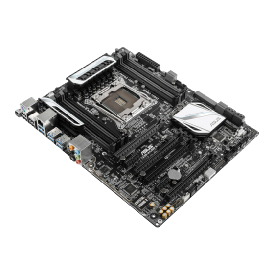
Page 19: Motherboard Overview
Before you install or remove any component, ensure that the ATX power supply is switched off or the power cord is detached from the power supply. Failure to do so may cause severe damage to the motherboard, peripherals, or components. ASUS X99-A/USB 3.1... -
Page 20: Motherboard Layout
1.2.2 Motherboard layout Refer to 1.2.9 Internal connectors and 2.3.1 Rear I/O connection for more information about rear panel connectors and internal connectors. Chapter 1: Product introduction... - Page 21 22. Serial port connector (10-1 pin COM) 1-40 23. Front panel audio connector (10-1 pin AAFP) 1-41 24. Digital audio connector (4-1 pin SPDIF_OUT) 1-32 25. CPU Over Voltage jumper (3-pin CPU_OV) 1-24 26. Thunderbolt header (5-pin TB_HEADER) 1-39 ASUS X99-A/USB 3.1...
-
Page 22: Central Processing Unit (Cpu)
Contact your retailer immediately if the PnP cap is missing, or if you see any damage to the PnP cap/socket contacts/motherboard components. ASUS will shoulder the cost of repair only if the damage is shipment/ transit-related. -
Page 23: System Memory
The motherboard comes with eight DDR 4 (Double Data Rate 4) Quad Inline Memory Modules (DIMM) slots. A DDR4 module is notched differently from a DDR, DDR2, or DDR3 module. DO NOT install a DDR, DDR2, or DDR3 memory module to the DDR4 slot. Recommended memory configurations ASUS X99-A/USB 3.1... - Page 24 Memory configurations You may install 2 GB, 4 GB and 8 GB unbuffered and non-ECC DDR4 DIMMs into the DIMM sockets. • You may install varying memory sizes in Channel A, Channel B, Channel C, and Channel D. The system maps the total size of the lower-sized channel for the dual- channel configuration.
- Page 25 15-15-15-35 1.35V • • AVEXIR AVD4U30001608G-4CI 32GB(8GB*4) SK hynix H5AN4G8NMFR 16-18-18-36 1.35V • • Kingston HX430C15PB2K4/16 16GB(4GB*4) 15-16-16-39 1.35V • • CORSAIR CMD16GX4M4B3000C15 16GB(4GB*4) Samsung K4A4G085WD 15-17-17-35 1.35V • • CORSAIR CMK16GX4M4B3000C15 16GB(4GB*4) Samsung K4A4G085WD 15-17-17-35 1.35V ASUS X99-A/USB 3.1...
- Page 26 DDR4 2800 (O.C.) MHz capability (U-DIMM) Vendors Part No. Size Chip Chip NO. Timing Voltage DIMM socket Brand support (Optional) • • A_DATA AX4U2800W8G17-DRZ SK hynix H5AN4G8NMFR 17-18-18-36 1.2V • • A_DATA AX4U2800W4G17 16GB(4GB*4) SK hynix H5AN4G8NMFR 17-17-17-36 1.2V • •...
- Page 27 1.2V • • G.SKILL F4-2400C15Q-32GRB 32GB(8GB*4) 15-15-15-35 1.2V • • G.SKILL F4-2400C15Q-32GRK 32GB(8GB*4) 15-15-15-35 1.2V • • G.SKILL F4-2400C15Q-16GRR 16GB(4GB*4) 15-15-15-35 1.2V • • G.SKILL F4-2400C15Q-16GRB 16GB(4GB*4) 15-15-15-35 1.2V • • G.SKILL F4-2400C15Q-16GRK 16GB(4GB*4) 15-15-15-35 1.2V ASUS X99-A/USB 3.1 1-11...
- Page 28 DDR4 2400 (O.C.) MHz capability (U-DIMM) Vendors Part No. Size Chip Chip NO. Timing Voltage DIMM socket Brand support (Optional) • • G.SKILL F4-2400C15Q-32GNT 32GB(8GB*4) 15-15-15-35 1.2V • • G.SKILL F4-2400C15Q-16GNT 16GB(4GB*4) 15-15-15-35 1.2V • • • Crucial BLS4G4D240FSA.8FAD 16-16-16-40 1.2V •...
- Page 29 • Kingston KVR21R15S4/8 Samsung K4A4G045WD 15-15-15-36 1.2V • • • Samsung M393A1G40DB0-CPB Samsung K4A4G045WD 15-15-15-36 1.2V • • • Samsung M393A2G40DB0-CPB 16GB Samsung K4A4G045WD 15-15-15-36 1.2V • • • Team T4E1R10S62000 16GB Samsung K4A4G045WD 15-15-15-36 1.2V ASUS X99-A/USB 3.1 1-13...
- Page 30 Hyper DIMM support is subject to the physical characteristics of individual CPUs. Load the X.M.P. or D.O.C.P. settings in the BIOS for the hyper DIMM support. • Visit the ASUS website for the latest QVL. 1-14 Chapter 1: Product introduction...
-
Page 31: Expansion Slots
PCIe 2.0 x1_1 slot PCIe 2.0 x16_2 slot PCIe 2.0 x16_2 slot PCIe 3.0/2.0 x16_3 slot PCIe 3.0/2.0 x16_3 slot PCIe 2.0 x1_2 slot PCIe 2.0 x1_2 slot PCIe 3.0/2.0 x16_4 slot PCIe 3.0/2.0 x16_4 slot ASUS X99-A/USB 3.1 1-15... - Page 32 40-LANE CPU PCI Express 3.0 operating mode PCIe 3.0/2.0 x16_1 PCIe 3.0/2.0 x16_3 PCIe 3.0/2.0 x16_4 configuration Single VGA/ x16 (single VGA PCIe card recommended) Dual VGA/PCIe cards Triple VGA/ PCIe cards * When the M.2 x4 slot is occupied, the PCIe x16_4 slot will be disabled. 28-LANE CPU PCI Express 3.0 operating mode VGA configuration...
- Page 33 ASMedia U3 Controller – – shared – – – – – * PCIe x16_2 is set to x1 mode by default. When the bandwidth is manually switched to x4 mode, the IRQ assignment will be changed to A. ASUS X99-A/USB 3.1 1-17...
-
Page 34: Onboard Buttons And Switches
1.2.6 Onboard buttons and switches Onboard buttons and switches allow you to fine-tune performance when working on a bare or open-case system. This is ideal for overclockers and gamers who continually change settings to enhance system performance. Power-on button The motherboard comes with a power-on button that allows you to power up or wake up the system. - Page 35 BIOS default settings. A message will appear during POST reminding you that the BIOS has been restored to its default settings. • We recommend that you download and update to the latest BIOS version from www.asus.com after using the MemOK! function. ASUS X99-A/USB 3.1 1-19...
- Page 36 TPU switch With its two-level adjustment functions, the TPU allows you to automatically adjusts the CPU ratio and clock speed for an optimal system performance. • Enable this switch when the system is powered off. • When the TPU switch is set to Enabled (TPU_I: CPU Ratio Boost), the system automatically adjusts the CPU ratio for an enhanced performance.
- Page 37 • You may change the EPU settings in the software application or BIOS setup program and enable the EPU function at the same time. However, the system will use the last setting you have made. ASUS X99-A/USB 3.1 1-21...
- Page 38 EZ XMP switch Enable this switch to overclock the installed DIMMs, allowing you to enhance the DIMM’s speed and performance. The EZ XMP LED (XLED1) lights up when you enable the EZ XMP switch. the location of the EZ XMP LED, refer to section 1.2.8 Onboard LEDs. 1-22 Chapter 1: Product introduction...
-
Page 39: Jumpers
• Due to the chipset behavior, AC power off is required to enable C.P.R. function. You must turn off and on the power supply or unplug and plug the power cord before rebooting the system. ASUS X99-A/USB 3.1 1-23... - Page 40 CPU Over Voltage jumper (3-pin CPU_OV) The CPU Over Voltage jumper allows you to set a higher CPU voltage for a flexible overclocking system, depending on the type of the installed CPU. To gain more CPU voltage setting, insert the jumper to pins 2-3. To go back to its default CPU voltage setting, insert the jumper to pins 1-2.
-
Page 41: Onboard Leds
(Power-On-Self Test): CPU, memory modules, VGA card, and hard disk drives. If an error is found, the critical component’s LED stays lit up until the problem is solved. TPU LED (TPU_LED) The TPU LED lights up when the TPU switch is enabled. ASUS X99-A/USB 3.1 1-25... - Page 42 EPU LED (O2LED3) The EPU LED lights up when the EPU switch is enabled. EZ XMP LED (XLED) This LED lights up when you enable the EZ XMP switch. 1-26 Chapter 1: Product introduction...
- Page 43 Memory initialization error. Invalid memory type or incompatible memory speed DXE IPL is started Unspecified memory initialization error Memory not installed Invalid CPU type or Speed CPU mismatch CPU self test failed or possible CPU cache error (continued on the next page) ASUS X99-A/USB 3.1 1-27...
- Page 44 Code Description Not used microcode CACHE_ENABLED PCH initialization CPU_EARLY_INIT PEI Core is started 11 – 14 Pre-memory CPU initialization is started 15 – 18 Pre-memory System Agent initialization is started 19 – 1C Pre-memory PCH initialization is started 2B – 2F Memory initialization Reserved for ASL (see ASL Status Codes section below) Memory Installed...
- Page 45 CPU initialization error System Agent initialization error PCH initialization error Some of the Architectural Protocols are not available PCI resource allocation error. Out of Resources No Space for Legacy Option ROM (continued on the next page) ASUS X99-A/USB 3.1 1-29...
- Page 46 Code Description No Console Output Devices are found No Console Input Devices are found Invalid password Error loading Boot Option (LoadImage returned error) Boot Option is failed (StartImage returned error) Flash update is failed Reset protocol is not available ACPI/ASL Checkpoints (under OS) Code Description System is entering S3 sleep state...
-
Page 47: Internal Connectors
• The SATAEXPRESS_1 connector can support one SATA Express device or two SATA devices. • Due to chipset behavior, the SATA6G_78 and SATA6G_910 ports (black) do not Rapid Storage Technology and RAID configuration. ® support Intel ASUS X99-A/USB 3.1 1-31... - Page 48 Digital audio connector (4-1 pin SPDIF_OUT) This connector is for an additional Sony/Philips Digital Interface (S/PDIF) port. Connect the S/PDIF Out module cable to this connector, then install the module to a slot opening at the back of the system chassis. The S/PDIF module is purchased separately.
- Page 49 The plugged USB 3.0 device may run on xHCI or EHCI mode depending on the operating system’s setting. • These USB 3.0 ports support native UASP transfer standard in Windows ® Windows ® 8.1 and Turbo Mode when using USB 3.0 Boost feature. ASUS X99-A/USB 3.1 1-33...
- Page 50 DO NOT connect a 1394 cable to the USB connectors. Doing so will damage the motherboard! You can connect the front panel USB cable to the ASUS Q-Connector (USB) first, and then install the Q-Connector (USB) to the USB connector onboard if your chassis supports front panel USB ports.
- Page 51 • The CPU_FAN connector supports the CPU fan of maximum 1A (12 W) fan power. • The CPU_FAN, CHA_FAN, and EXT_FAN connectors support the ASUS FAN Xpert 3 feature on X99 platform. • The EXT_FAN connector supports 2 of 5 thermal sensor sources.
- Page 52 1000W power or above to ensure the system stability. • If you are uncertain about the minimum power supply requirement for your system, refer to the Recommended Power Supply Wattage Calculator at http://support.asus. com/PowerSupplyCalculator/PSCalculator.aspx?SLanguage=en-us for details. 1-36 Chapter 1: Product introduction...
- Page 53 Pressing the power switch for more than four seconds while the system is ON turns the system OFF. • Reset button (2-pin RESET) This 2-pin connector is for the chassis-mounted reset button for system reboot without turning off the system power. ASUS X99-A/USB 3.1 1-37...
- Page 54 TPM connector (20-1 pin TPM) This connector supports a Trusted Platform Module (TPM) system, which securely store keys, digital certificates, passwords and data. A TPM system also helps enhance network security, protect digital identities, and ensures platform integrity. The TPM module is purchased separately. DirectKey connector (2-pin DRCT) This connector is for the chassis-mounted button that supports the DirectKey function.
- Page 55 The add-on Thunderbolt I/O card and Thunderbolt cables are purchased separately. T_Sensor connector (2-pin T_SENSOR1) This connector is for the thermistor cable that allows you to monitor the temperature of your motherboard’s critical components and connected devices. The thermistor cable is purchased separately. ASUS X99-A/USB 3.1 1-39...
- Page 56 Chassis intrusion connector (4-1 pin CHASSIS) This connector is for a chassis-mounted intrusion detection sensor or switch. Connect one end of the chassis intrusion sensor or switch cable to this connector. The chassis intrusion sensor or switch sends a high-level signal to this connector when a chassis component is removed or replaced.
- Page 57 • If you want to connect a high-definition or an AC’97 front panel audio module to this connector, set the Front Panel Type item in the BIOS setup to [HD] or [AC97]. ASUS X99-A/USB 3.1 1-41...
- Page 58 1-42 Chapter 1: Product introduction...
-
Page 59: Chapter 2: Basic Installation
The diagrams in this section are for reference only. The motherboard layout may vary with models, but the installation steps are the same for all models. Install the ASUS Q-Shield to the chassis rear I/O panel. Place the motherboard into the chassis, ensuring that its rear I/O ports are aligned to the chassis’... - Page 60 Place nine screws into the holes indicated by circles to secure the motherboard to the chassis. DO NOT overtighten the screws! Doing so can damage the motherboard. Chapter 2: Basic installation...
-
Page 61: Cpu Installation
Please note the order in opening/ closing the double latch. Follow the instructions printed on the metal sealing hatch or the illustrations shown below in this manual. The plastic cap will pop up automatically once the CPU is in place and the hatch properly sealed down. Triangle mark Triangle mark ASUS X99-A/USB 3.1... -
Page 62: Cpu Heatsink And Fan Assembly Installation
2.1.3 CPU heatsink and fan assembly installation Apply the Thermal Interface Material to the CPU heatsink and CPU before you install the heatsink and fan, if necessary. Chapter 2: Basic installation... - Page 63 To install the CPU heatsink and fan assembly ASUS X99-A/USB 3.1...
-
Page 64: Dimm Installation
2.1.4 DIMM installation To remove a DIMM Chapter 2: Basic installation... -
Page 65: Atx Power Connection
2.1.5 ATX Power connection ASUS X99-A/USB 3.1... -
Page 66: Sata Device Connection
2.1.6 SATA device connection Chapter 2: Basic installation... -
Page 67: Front I/O Connector
2.1.7 Front I/O Connector To install ASUS Q-Connector To install USB 2.0 connector To install front panel audio connector AAFP USB 2.0 To install USB 3.0 connector USB 3.0 ASUS X99-A/USB 3.1... -
Page 68: Expansion Card Installation
2.1.8 Expansion Card installation To install PCIe x16 cards To install PCIe x1 cards 2-10 Chapter 2: Basic installation... -
Page 69: Bios Update Utility
BIOS Flashback is not operating properly. This may be caused by improper installation of the USB storage device and filename/file format error. If this scenario happens, please restart the system to turn off the light. • Updating BIOS may have risks. If the BIOS program is damaged during the process and results to the system’s failure to boot up, please contact your local ASUS Service Center. ASUS X99-A/USB 3.1 2-11... -
Page 70: Motherboard Rear And Audio Connections
Motherboard rear and audio connections 2.3.1 Rear I/O connection Rear panel connectors Keyboard/Mouse combo port USB 3.1 ports E56 (Support USB 3.1 Boost) ® Intel LAN port USB 3.0 ports E34 (Supports USB 3.0 Boost) USB 3.0 ports E2_5 (Supports USB USB BIOS Flashback 3.0 Boost) USB 2.0 ports 78 (bottom port Optical S/PDIF Out port supports USB BIOS Flashback) - Page 71 Line In Side Speaker Out Lime Line Out Front Speaker Out Front Speaker Out Front Speaker Out Pink Mic In Mic In Mic In Mic In Orange – – Center/Subwoofer Center/Subwoofer Rear Speaker Out Rear Speaker Out Rear Speaker Out Black – ASUS X99-A/USB 3.1 2-13...
-
Page 72: Audio I/O Connections
2.3.2 Audio I/O connections Audio I/O ports Connect to Headphone and Mic Connect to Stereo Speakers Connect to 2.1 channel Speakers 2-14 Chapter 2: Basic installation... - Page 73 Connect to 4.1 channel Speakers Connect to 5.1 channel Speakers If you are using Windows ® 8.1 platform, use only the gray audio port for Side Speaker Out in a 6-channel configuration. ASUS X99-A/USB 3.1 2-15...
-
Page 74: Starting Up For The First Time
Connect to 7.1 channel Speakers When the DTS UltraPC II function is enabled, ensure to connect the rear speaker to the light blue port. Starting up for the first time After making all the connections, replace the system case cover. Ensure that all switches are off. -
Page 75: Turning Off The Computer
While the system is ON, press the power button for less than four seconds to put the system on sleep mode or soft-off mode, depending on the BIOS setting. Press the power switch for more than four seconds to let the system enter the soft-off mode regardless of the BIOS setting. ASUS X99-A/USB 3.1 2-17... - Page 76 2-18 Chapter 2: Basic installation...
-
Page 77: Chapter 3: Bios Setup
BIOS setup Knowing BIOS The new ASUS UEFI BIOS is a Unified Extensible Interface that complies with UEFI architecture, offering a user-friendly interface that goes beyond the traditional keyboard- only BIOS controls to enable a more flexible and convenient mouse input. You can easily navigate the new UEFI BIOS with the same smoothness as your operating system. -
Page 78: Bios Setup Program
BIOS setup program Use the BIOS Setup to update the BIOS or configure its parameters. The BIOS screen include navigation keys and brief onscreen help to guide you in using the BIOS Setup program. Entering BIOS at startup To enter BIOS Setup at startup, press <Delete> during the Power-On Self Test (POST). If you do not press <Delete>, POST continues with its routines. -
Page 79: Ez Mode
Displays the CPU Fan’s speed. Click Selects the boot default settings the button to manually tune the fans device priority Saves the changes and resets the system The boot device options vary depending on the devices you installed to the system. ASUS X99-A/USB 3.1... -
Page 80: Advanced Mode
3.2.2 Advanced Mode The Advanced Mode provides advanced options for experienced end-users to configure the BIOS settings. The figure below shows an example of the Advanced Mode. Refer to the following sections for the detailed configurations. To switch from EZ Mode to Advanced Mode, click Advanced Mode or press F7 hotkey. Q-Fan control EZ Tuning Wizard MyFavorite... - Page 81 This button above the menu bar allows you to view and tweak the overclocking settings of your system. It also allows you to change the motherboard’s SATA mode from AHCI to RAID mode. Refer to section 3.2.4 EZ Tuning Wizard for more information. ASUS X99-A/USB 3.1...
- Page 82 Quick Note (F9) This button above the menu bar allows you to key in notes of the activities that you have done in BIOS. • The Quick Note function does not support the following keyboard functions: delete, cut, copy and paste. •...
-
Page 83: Qfan Control
Click to activate DC Mode configured PWM Mode Select a profile to apply to Click to apply the fan setting your fans Click to undo the Click to go back to main menu changes Select to manually configure your fans ASUS X99-A/USB 3.1... - Page 84 Configuring fans manually Select Manual from the list of profiles to manually configure your fans’ operating speed. Speed points Click or tap to manually configure your fans To configure your fans: Select the fan that you want to configure and to view its current status. Click and drag the speed points to adjust the fans’...
-
Page 85: Ez Tuning Wizard
Select the CPU fan type (Box cooler, Tower cooler, or Water cooler) that you installed then click Next. If you are not sure of the CPU fan type, click I’m not sure. The system automatically detects the CPU fan type. Click Next then click Yes to confirm auto-tuning. ASUS X99-A/USB 3.1... - Page 86 Creating RAID To create RAID: Press <F11> on your keyboard or click from the BIOS screen to open EZ Tuning Wizard screen. Click RAID then click Next. • Ensure that your HDDs have no existing RAID volumes. • Ensure to connect your HDDs to Intel SATA connectors.
-
Page 87: My Favorites
My Favorites MyFavorites is your personal space where you can easily save and access your favorite BIOS items. ASUS X99-A/USB 3.1 3-11... - Page 88 Adding items to My Favorites To add BIOS items: Press <F3> on your keyboard or click from the BIOS screen to open Setup Tree Map screen. On the Setup Tree Map screen, select the BIOS items that you want to save in MyFavorites screen.
-
Page 89: Main Menu
RTC RAM via the Clear CMOS button. • The Administrator or User Password items on top of the screen show the default [Not Installed]. After you set a password, these items show [Installed]. ASUS X99-A/USB 3.1 3-13... - Page 90 Administrator Password If you have set an administrator password, we recommend that you enter the administrator password for accessing the system. Otherwise, you might be able to see or change only selected fields in the BIOS setup program. To set an administrator password: Select the Administrator Password item and press <Enter>.
-
Page 91: Ai Tweaker Menu
This item allows you to select a strap close to your target BCLK (base clock) for an extreme overclocking, or leave it at [Auto] for the BIOS to upgrade. Configuration options: [Auto] [100MHz] [125MHz] [166MHz] [250MHz] 3-15 ASUS X99-A/USB 3.1... - Page 92 The value ranges depend on the value you set on BCLK Frequency. ASUS MultiCore Enhancement [Auto] [Auto] This item allows you to maximize the oveclocking performance optimized by ASUS core ratio settings. [Disabled] This item allows you to set to default core ratio settings. CPU Core Ratio [Auto] This item allows you to set the CPU core ratio limit per core or synchronize automatically to all cores.
- Page 93 Max. CPU Cache Ratio [Auto] This item allows you to set the maximum possible ratio on the Uncore part of the processor. Use the <+> or <-> keys to adjust the value. The values depend on the CPU installed. 3-17 ASUS X99-A/USB 3.1...
- Page 94 [Keep Current Settings]. EPU Power Saving Mode [Disabled] The ASUS EPU (Energy Processing Unit) sets the CPU in its minimum power consumption settings. Enable this item to set lower CPU VCCIN and Vcore voltages and achieve the best energy saving condition.
- Page 95 Configuration options: [Auto] [1] – [15] DRAM WRITE to READ Delay(tWTR_L) [Auto] Configuration options: [Auto] [1] – [15] DRAM CKE Minimum Pulse Width [Auto] Configuration options: [Auto] [4] – [8] DRAM Write Latency [Auto] Configuration options: [Auto] [1] – [31] ASUS X99-A/USB 3.1 3-19...
- Page 96 Third Timings tRRDR [Auto] Configuration options: [Auto] [1] - [7] tRRDD [Auto] Configuration options: [Auto] [1] - [7] tWWDR [Auto] Configuration options: [Auto] [1] - [7] tWWDD [Auto] Configuration options: [Auto] [1] - [7] tRWDR [Auto] Configuration options: [Auto] [1] - [7] tWRDR [Auto] Configuration options: [Auto] [1] - [7] tWRDD [Auto]...
- Page 97 DRAM IO-L (CHB D0 R0) [Auto] Configuration options: [Auto] [1] - [255] DRAM IO-L (CHB D0 R1) [Auto] Configuration options: [Auto] [1] - [255] DRAM IO-L (CHB D1 R0) [Auto] Configuration options: [Auto] [1] - [255] ASUS X99-A/USB 3.1 3-21...
- Page 98 DRAM IO-L (CHB D1 R1) [Auto] Configuration options: [Auto] [1] - [255] DRAM IO-L (CHC D0 R0) [Auto] Configuration options: [Auto] [1] - [255] DRAM IO-L (CHC D0 R1) [Auto] Configuration options: [Auto] [1] - [255] DRAM IO-L (CHC D1 R0) [Auto] Configuration options: [Auto] [1] - [255] DRAM IO-L (CHC D1 R1) [Auto] Configuration options: [Auto] [1] - [255]...
- Page 99 Configuration options: [Auto] [1.00] - [1.60] Receiver ODT Pre-emphasis [Auto] Configuration options: [Auto] [1.00] - [1.60] Transmitter ODT Pre-emphasis [Auto] Configuration options: [Auto] [1.00] - [1.60] Transmitter ODT De-emphasis [Auto] Configuration options: [Auto] [1.00] - [1.60] ASUS X99-A/USB 3.1 3-23...
- Page 100 MISC DRAM Eventual Voltage (CHA/CHB/CHC/CHD) [Auto] Use <+> or <-> to adjust the eventual voltages of the DIMM slots. The values range from 0.8 V to 1.9 V with a 0.10 V increment. DRAM CLK Period [Auto] This item allows you to set a DRAM clock period. Configuration options: [Auto] [1] –...
- Page 101 DIGI + VRM Duty Control adjusts the current of every VRM phase and the thermal conditions of every phase component. [T. Probe] Select to maintain the VRM thermal balance. [Extreme] Select to maintain the current VRM balance. 3-25 ASUS X99-A/USB 3.1...
- Page 102 DO NOT remove the thermal module. The thermal conditions should be monitored. CPU Current Capability [Auto] This item provides a total power range for CPU overclocking. A higher value setting provides higher power consumption delivery and extends the overclocking frequency range simultaneously.
- Page 103 Configuration options: [Disabled] [Enabled] You can only enable this item if you enable the CPU OverVoltage jumper on your motherboard. Refer to section 1.2.2 Motherboard layout for the location of the CPU Overvoltage jumper. 3-27 ASUS X99-A/USB 3.1...
- Page 104 Fully Manual Mode [Disabled] Enable this item to configure the CPU-related voltages. This ASUS exclusive mode provides the optimum voltage adjusting capability for the CPU core, cache, and system agent voltages. You can adjust these voltages separately without the restrictions from the CPU Configuration options: [Disabled] [Enabled] The following items appear only when you set Fully Manual Mode item to [Enabled].
- Page 105 0.001 V to 1.920 V with a 0.001 V interval. Total Adaptive Mode CPU Cache Voltage [Auto] This item sums up the voltages of the CPU Cache Voltage offset and Additional Turbo Mode CPU Cache Voltage options. ASUS X99-A/USB 3.1 3-29...
- Page 106 CPU SVID Support [Auto] Set this item to [Enabled] when overclocking. Disabling this item prevents the CPU from communicating with the external voltage regulator. Configuration options: [Auto] [Disabled] [Enabled] The following items appear only when you set the CPU Core Voltage to [Enabled]. SVID Voltage Override[Auto] This item allows you to set a VCCIN for the CPU during initial part of POST.
- Page 107 This item allows you to enhance the BCLK overclocking capability or reduce the EMI (electromagnetic disturbance) generated by the BCLK. Set this item to [Enabled] for EMI reduction, or set this item to [Disabled] to enhance BCLK overclocking. Configuration options: [Auto] [Disabled] [Enabled] ASUS X99-A/USB 3.1 3-31...
-
Page 108: Advanced Menu
Advanced menu The Advanced menu items allow you to change the settings for the CPU and other system devices. Be cautious when changing the settings of the Advanced menu items. Incorrect field values can cause the system to malfunction. 3-32 Chapter 3: BIOS setup... -
Page 109: Cpu Configuration
Configuration options: [Disabled] [Enabled] Execute Disable Bit [Enabled] Execute Disable prevents certain classes of malicious buffer overflow attacks when combined with a supporting OS (SuSE Linux 9.2, RedHat Enterprise 3 Update 3). Configuration options: [Disabled] [Enabled] ASUS X99-A/USB 3.1 3-33... - Page 110 Intel Virtualization Technology [Disabled] When set to [Enabled], a VMM can utilize the additional hardware capabilities provided by Vanderpool Technology. Configuration options: [Disabled] [Enabled] Hardware Prefetcher [Enabled] This item allows the CPU to prefetch commands and data in the L2 cache, reduces the DRAM loading time and improves the system performance.
-
Page 111: Pch Configuration
This item allows your system to select the speed for PCIe x1_2 slot. When set to [Gen1], the PCI-E port runs at PCI-E 1.0 speed. When set to [Gen2], the PCI-E port runs at PCI-E 2.0 speed. Configuration options: [Auto] [Gen1] [Gen2] 3-35 ASUS X99-A/USB 3.1... -
Page 112: Pch Storage Configuration
When set to [Auto], this item allows the system to automatically adjust the SRIS (Separate Reference Clock Independent Spread Spectrum Clocking Architecture) support for connected SATA Express devices. Set this item to [Disabled] to activate ASUS RUNWAY SATA Express bridge card Configuration options: [Auto] [Disabled] S.M.A.R.T. - Page 113 When disabled, the hot plug function of SATA ports are disabled. Configuration options: [Disabled] [Enabled] Hot Plug [Disabled] (SATA6G_1-6 (Gray) / SATA6G_7-10 (Black)) These items allow you to enable/disable SATA Hot Plug Support. Configuration options: [Disabled] [Enabled] 3-37 ASUS X99-A/USB 3.1...
-
Page 114: System Agent Configuration
3.6.4 System Agent Configuration DMI Configuration The item in this menu allows your DMI (direct media interface) to run at PCI-E 2.0 speed. DMI Gen 2 Configuration options: [Disabled] [Enabled] NB PCI-E Configuration The items in this menu allow you to select the operating speeds of the PCIe slots. PCIEX16_1 Link Speed [Auto] This item allows you to select the operating speed of the PCIEX16_1 slot. -
Page 115: Usb Configuration
[Smart Auto] Upon detection, the xHCI driver supports the USB 3.0 mode during both POST and operating system. [Enabled] Enables the xHCI controller. [Disabled] Disables the xHCI controller. ASUS X99-A/USB 3.1 3-39... - Page 116 xHCI Legacy USB Support [Enabled] [Enabled] Your system supports the USB 3.0 devices in legacy operating systems. [Disabled] Your USB 3.0 devices can be used for BIOS setup only and cannot be recognized in the boot devices list. [Auto] Your system automatically detects the presence of USB3.0 devices at startup.
-
Page 117: Platform Misc Configuration
This item allows you to enable/disable the PCH DMI ASPM Setting. Configuration options: [Disabled] [Enabled] ASPM Support [Disabled] This item allows you to enable/disable the ASPM support for all downstream devices. Configuration options: [Disabled] [L1 only] ASUS X99-A/USB 3.1 3-41... -
Page 118: Onboard Devices Configuration
3.6.7 Onboard Devices Configuration Scroll down to view the other BIOS items. HD Audio Controller [Enabled] This item allows you to use the Azalia High Definition Audio Controller Configuration options: [Disabled] [Enabled] The following items appear only when you set the HD Audio Controller to [Enabled]. Front Panel Type [HD Audio] This item allows you to set the front panel audio connector (AAFP) mode to legacy AC’97 or high-definition audio depending on the audio standard that the front panel... - Page 119 The following item appears only when you set the Intel LAN Controller to [Enabled]. Intel PXE OPROM [On] This item allows you to turn on or turn off the PXE OptionRom of the Intel ® controller. Configuration options: [On] [Off] ASUS X99-A/USB 3.1 3-43...
-
Page 120: Apm Configuration
Serial Port Configuration The items in this menu allows you to set the parameters of the serial port. This items in this menu works only if a serial port connector is installed on the motherboard. Serial Port [On] This item allows you to enable/disable the serial port. Configuration options: [On] [Off] Change Settings [Auto] This item allows you to select an optimal setting for Super IO device. -
Page 121: Network Stack Configuration
Configuration options: [Disabled] [Enabled] The following item appears only when you set the Network Stack to [Enabled]. Ipv4/Ipv6 PXE Support [Enabled] This item allows you to enable/disable the Ipv4/Ipv6 PXE wake event. Configuration options: [Disabled] [Enabled] 3-45 ASUS X99-A/USB 3.1... -
Page 122: Monitor Menu
Monitor menu The Monitor menu displays the system temperature/power status, and allows you to change the fan settings. Scroll down to display the other BIOS items. CPU Temperature / MB Temperature / VRM Temperature / PCH Core Temperature / T-SENSOR1 Temperature / EXT_Sensor1 Temperature / EXT_ Sensor2 Temperature / EXT_Sensor3 Temperature [xxx°C/xxx°F] The onboard hardware monitor automatically detects and displays the CPU, motherboard, VRM, PCH Core, T-SENSOR1, and EXT_SENSOR1-3 temperatures. - Page 123 Use the <+> or <-> keys to adjust the CPU fan’s lower temperature. The values range from 20% to 75%. CPU Fan Min. Duty Cycle(%) [20] Use the <+> or <-> keys to adjust the minimum CPU fan duty cycle. The values may differ via Qfan tuning. 3-47 ASUS X99-A/USB 3.1...
- Page 124 Chassis Fan 1/4 Q-Fan Control [DC Mode] These items allow you to set the chassis fans’ Q-Fan control feature into DC Mode, PWM Mode, or disable these Q-Fan controls from your motherboard. Configuration options: [Disabled] [DC Mode] [PWM Mode] The following items appear only when you set the Chassis Fan 1/4 Q-Fan Control to [PWM Mode] or [DC Mode].
- Page 125 The values range from 40°C to 90°C. EXT Fan 1/3 Max. Duty Cycle(%) [100] Use the <+> or <-> keys to adjust the maximum extension fan duty cycle. The values may differ via Qfan tuning. ASUS X99-A/USB 3.1 3-49...
- Page 126 EXT Fan 1/3 Middle Temperature [45] Use the <+> or <-> keys to set the value for EXT Fan Middle Temperature. EXT Fan 1/3 Middle Duty Cycle(%) [60] Use the <+> or <-> keys to adjust the extension fan middle duty cycle. The values may differ via Qfan tuning.
-
Page 127: Boot Menu
POST time. [Full Initialization] All USB devices will be available during POST. This process will extend the POST time. [Partial For a faster POST time, only USB ports with keyboard and Initialization] mouse connections will be detected. 3-51 ASUS X99-A/USB 3.1... - Page 128 PS/2 Keyboard and Mouse Support [Auto] [Auto] For a faster POST time, PS/2 devices are available when the system boots up or rebooted when the PS/2 devices have not been reconnected or changed [Full For full system control, PS/2 devices are always available during Initialization] POST.
- Page 129 For better compatibility, enable the CSM to fully support the non-UEFI driver add-on devices or the Windows UEFI mode. ® [Disabled] Disables the CSM to fully support the non-UEFI driver add-on devices or the Windows UEFI mode. ® 3-53 ASUS X99-A/USB 3.1...
- Page 130 The following items appear only when you set the Launch CSM to [Enabled]. Boot Device Control [UEFI and Legacy OpROM] This item allows you to select the type of devices that you want to boot. Configuration options: [UEFI and Legacy OpROM] [Legacy OpROM only] [UEFI only] Boot from Network Devices [Legacy OpROM first] This item allows you to select the type of network devices that you want to...
- Page 131 This item allows you to load the downloaded db from a USB storage device. Append db from File This item allows you to load the additional db from a storage device so that more images can be loaded securely. 3-55 ASUS X99-A/USB 3.1...
- Page 132 ® ® supported). • To select the boot device during system startup, press <F8> when ASUS Logo appears. Boot Override These item displays the available devices. The number of device items that appear on the screen depends on the number of devices installed in the system. Click an item to start booting from the selected device.
-
Page 133: Tool Menu
3.9.1 ASUS EZ Flash 2 Utility This item allows you to run ASUS EZ Flash 2. When you press <Enter>, a confirmation message appears. Use the left/right arrow key to select between [Yes] or [No], then press <Enter> to confirm your choice. -
Page 134: Asus O.c. Profile
3.9.2 ASUS O.C. Profile This item allows you to store or load multiple BIOS settings. Load from Profile This item allows you to load the previous BIOS settings saved in the BIOS Flash. Key in the profile number that saved your BIOS settings, press <Enter>, and then select Yes. -
Page 135: Asus Dram Spd Information
3.9.3 ASUS DRAM SPD Information This item allows you to view the DRAM SPD information. 3-59 ASUS X99-A/USB 3.1... -
Page 136: Exit Menu
3.10 Exit menu The Exit menu items allow you to load the optimal default values for the BIOS items, and save or discard your changes to the BIOS items. You can access the EZ Mode from the Exit menu. Load Optimized Defaults This option allows you to load the default values for each of the parameters on the Setup menus. -
Page 137: Updating Bios
3.11.2 ASUS EZ Flash 2 ASUS EZ Flash 2 allows you to update the BIOS without having to use a bootable floppy disk or an OS-based utility. Before you start using this utility, download the latest BIOS from the ASUS website at www.asus.com. - Page 138 Press <Tab> to switch to the Drive field. Press the Up/Down arrow keys to find the USB flash disk that contains the latest BIOS, and then press <Enter>. Press <Tab> to switch to the Folder Info field. Press the Up/Down arrow keys to find the BIOS file, and then press <Enter> to perform the BIOS update process.
-
Page 139: Asus Crashfree Bios 3
The BIOS file in the motherboard support DVD may be older than the BIOS file published on the ASUS official website. If you want to use the newer BIOS file, download the file at http://support.asus.com and save it to a USB flash drive. - Page 140 Boot your computer then press <F8> to launch the select boot device screen. When the select boot device screen appears, insert the Support DVD into the optical drive then select the optical drive as the boot device. Please select boot device: ASUS DVD-E818A6T (4069MB) USB DISK 2.0 (3824MB) UEFI: (FAT) USB DISK 2.0 (3824MB)
- Page 141 BIOS Updater will automatically check the selected BIOS file and enter ASUS EZ Flash 2 Updater to continue the BIOS update process. When BIOS update is done, select OK or press <Enter> to restart your computer. Updating in GUI environment: On the FreeDOS prompt, type bupdater /g and press <Enter>.
- Page 142 Press <Enter> again to launch secure BIOS update. System will enter EZ Flash 2 Updater and continue the BIOS update process. When the BIOS update is done, select OK or press <Enter> to restart your computer. DO NOT shut down or reset the system while updating the BIOS to prevent system boot failure.
-
Page 143: Appendices
Consult the dealer or an experienced radio/TV technician for help. The use of shielded cables for connection of the monitor to the graphics card is required to assure compliance with FCC regulations. Changes or modifications to this unit not expressly approved by the party responsible for compliance could void the user’s authority to operate this equipment. ASUS X99-A/USB 3.1... - Page 144 IC: Canadian Compliance Statement Complies with the Canadian ICES-003 Class B specifications. This device complies with RSS 210 of Industry Canada. This Class B device meets all the requirements of the Canadian interference-causing equipment regulations. This device complies with Industry Canada license exempt RSS standard(s). Operation is subject to the following two conditions: (1) this device may not cause interference, and (2) this device must accept any interference, including interference that may cause undesired operation of the device.
- Page 145 ASUS Recycling/Takeback Services ASUS recycling and takeback programs come from our commitment to the highest standards for protecting our environment. We believe in providing solutions for you to be able to responsibly recycle our products, batteries, other components as well as the packaging materials.
- Page 146 Slovenščina AsusTek Inc. tukaj izjavlja, da je ta naprava skladna s di conformità CE. temeljnimi zahtevami in drugimi relevantnimi določili direktiv CE. Za več Компания ASUS заявляет, что это устройство соответствует основным informacij glejte Izjavo CE o skladnosti. требованиям и другим соответствующим условиям европейских...
-
Page 147: Asus Contact Information
+1-510-739-3777 +1-510-608-4555 Web site http://www.asus.com/us/ Technical Support Support fax +1-812-284-0883 Telephone +1-812-282-2787 Online support http://www.service.asus.com/ ASUS COMPUTER GmbH (Germany and Austria) Address Harkort Str. 21-23, D-40880 Ratingen, Germany +49-2102-959911 Web site http://www.asus.com/de Online contact http://eu-rma.asus.com/sales Technical Support Telephone +49-1805-010923* Support Fax... - Page 148 Appendices...