Table of Contents
Advertisement
Advertisement
Table of Contents

Related Manuals for ASROCK Super Alloy H110M-HDV


Summary of Contents for ASROCK Super Alloy H110M-HDV
-
Page 2: Copyright Notice
(including damages for loss of profits, loss of business, loss of data, interruption of business and the like), even if ASRock has been advised of the possibility of such damages arising from any defect or error in the documentation or product. - Page 3 The terms HDMI™ and HDMI High-Definition Multimedia Interface, and the HDMI logo are trademarks or registered trademarks of HDMI Licensing LLC in the United States and other countries.
-
Page 4: Table Of Contents
Expansion Slots (PCI Express Slots) Jumpers Setup Onboard Headers and Connectors Chapter 3 Software and Utilities Operation Installing Drivers ASRock Live Update & APP Shop 3.2.1 UI Overview 3.2.2 Apps 3.2.3 BIOS & Drivers 3.2.4 Setting Enabling USB Ports for Windows® 7 Installation... - Page 5 4.1.1 UEFI Menu Bar 4.1.2 Navigation Keys Main Screen OC Tweaker Screen Advanced Screen 4.4.1 CPU Configuration 4.4.2 Chipset Configuration 4.4.3 Storage Configuration 4.4.4 Super IO Configuration 4.4.5 ACPI Configuration 4.4.6 USB Configuration 4.4.7 Trusted Computing Tools Hardware Health Event Monitoring Screen Security Screen Boot Screen Exit Screen...
-
Page 6: Chapter 1 Introduction
ASRock’s website without further notice. If you require technical support related to this motherboard, please visit our website for specific information about the model you are using. You may find the latest VGA cards and CPU support list on ASRock’s website as well. ASRock website http://www.asrock.com. -
Page 7: Specifications
1.2 Specifications Platform • Micro ATX Form Factor • Solid Capacitor design • High Density Glass Fabric PCB • Supports 6 Generation Intel® Core i7/i5/i3/Pentium®/ Celeron® Processors (Socket 1151) • Supports Intel® Turbo Boost 2.0 Technology Chipset • Intel® H110 Memory • Dual Channel DDR4 Memory Technology • 2 x DDR4 DIMM Slots... - Page 8 • 1 x D-Sub Port • 1 x DVI-D Port • 1 x HDMI Port • 4 x USB 2.0 Ports (Supports ESD Protection (ASRock Full Spike Protection)) • 2 x USB 3.0 Ports (Supports ESD Protection (ASRock Full Spike Protection)) • 1 x RJ-45 LAN Port with LED (ACT/LINK LED and SPEED...
- Page 9 * To install Windows® 7 OS, a modified installation disk with xHCI drivers packed into the ISO file is required. Please refer to page 30 for more detailed instructions. * For the updated Windows® 10 driver, please visit ASRock’s website for details: http://www.asrock.com...
- Page 10 • ErP/EuP Ready (ErP/EuP ready power supply is required) * For detailed product information, please visit our website: http://www.asrock.com Please realize that there is a certain risk involved with overclocking, including adjusting the setting in the BIOS, applying Untied Overclocking Technology, or using third-party overclocking tools.
-
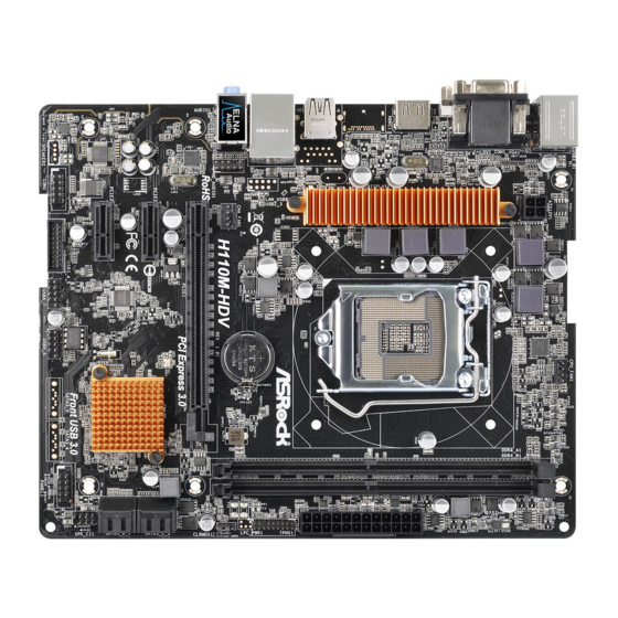
Page 11: Motherboard Layout
1.3 Motherboard Layout CPU_FAN1 ATX12V1 USB 2.0 T: USB2 B: USB3 USB 2.0 Top: T: USB0 RJ-45 B: USB1 CMOS HD_AUDIO1 Battery CHA_FAN1 H110M-HDV PCIE1 PCI Express 3.0 RoHS PCIE2 Intel H110 PCIE3 Front USB 3.0 PLED PWRBTN PANEL1 COM1 USB3_4_5 USB_6_7 USB_4_5... - Page 12 H110M-HDV No. Description ATX 12V Power Connector (ATX12V1) CPU Fan Connector (CPU_FAN1) 2 x 288-pin DDR4 DIMM Slots (DDR4_A1, DDR4_B1) ATX Power Connector (ATXPWR1) TPM Header (TPMS1) Clear CMOS Jumper (CLRMOS1) SATA3 Connectors (SATA3_2_3) SATA3 Connectors (SATA3_4_5) Chassis Intrusion and Speaker Header (SPK_CI1) System Panel Header (PANEL1) USB 2.0 Header (USB_4_5) USB 2.0 Header (USB_6_7)
-
Page 13: I/O Panel
1.4 I/O Panel No. Description No. Description PS/2 Mouse/Keyboard Port USB 2.0 Ports (USB01) D-Sub Port USB 2.0 Ports (USB_23) LAN RJ-45 Port* HDMI Port Line In (Light Blue)** DVI-D Port Front Speaker (Lime)** USB 3.0 Ports (USB3_01) Microphone (Pink)** * There are two LEDs on the LAN port. - Page 14 H110M-HDV ** To configure 7.1 CH HD Audio, it is required to use an HD front panel audio module and enable the multi- channel audio feature through the audio driver. Please set Speaker Configuration to “7.1 Speaker”in the Realtek HD Audio Manager. Function of the Audio Ports in 7.1-channel Configuration: Port Function...
-
Page 15: Chapter 2 Installation
Chapter 2 Installation This is a Micro ATX form factor motherboard. Before you install the motherboard, study the configuration of your chassis to ensure that the motherboard fits into it. Pre-installation Precautions Take note of the following precautions before you install motherboard components or change any motherboard settings. -
Page 16: Installing The Cpu
H110M-HDV 2.1 Installing the CPU 1. Before you insert the 1151-Pin CPU into the socket, please check if the PnP cap is on the socket, if the CPU surface is unclean, or if there are any bent pins in the socket. - Page 18 H110M-HDV Please save and replace the cover if the processor is removed. The cover must be placed if you wish to return the motherboard for after service.
-
Page 19: Installing The Cpu Fan And Heatsink
2.2 Installing the CPU Fan and Heatsink... -
Page 20: Installing Memory Modules (Dimm)
H110M-HDV 2.3 Installing Memory Modules (DIMM) This motherboard provides two 288-pin DDR4 (Double Data Rate 4) DIMM slots, and supports Dual Channel Memory Technology. 1. For dual channel configuration, you always need to install identical (the same brand, speed, size and chip-type) DDR4 DIMM pairs. 2. -
Page 22: Expansion Slots (Pci Express Slots)
H110M-HDV 2.4 Expansion Slots (PCI Express Slots) There are 3 PCI Express slots on the motherboard. Before installing an expansion card, please make sure that the power supply is switched off or the power cord is unplugged. Please read the documentation of the expansion card and make necessary hardware settings for the card before you start the installation. -
Page 23: Jumpers Setup
2.5 Jumpers Setup The illustration shows how jumpers are setup. When the jumper cap is placed on the pins, the jumper is “Short”. If no jumper cap is placed on the pins, the jumper is “Open”. The illustration shows a 3-pin jumper whose pin1 and pin2 are “Short” when a jumper cap is placed on these 2 pins. -
Page 24: Onboard Headers And Connectors
H110M-HDV 2.6 Onboard Headers and Connectors Onboard headers and connectors are NOT jumpers. Do NOT place jumper caps over these headers and connectors. Placing jumper caps over the headers and connectors will cause permanent damage to the motherboard. System Panel Header Connect the power PLED+ PLED-... - Page 25 Chassis Intrusion and Please connect the SPEAKER DUMMY Speaker Header chassis intrusion and the DUMMY (7-pin SPK_CI1) chassis speaker to this (see p.6, No. 9) header. SIGNAL DUMMY Serial ATA3 Connectors These four SATA3 (SATA3_4_5: connectors support SATA see p.6, No. 8) data cables for internal (SATA3_2_3: storage devices with up to...
-
Page 26: Atx Power Connector
H110M-HDV Front Panel Audio Header This header is for OUT_RET OUT2_L (9-pin HD_AUDIO1) connecting audio devices J_SENSE MIC_RET OUT2_R (see p.6, No. 16) to the front audio panel. PRESENCE# MIC2_R GN D MIC2_L 1. High Definition Audio supports Jack Sensing, but the panel wire on the chassis must support HDA to function correctly. - Page 27 ATX 12V Power This motherboard Connector provides an 4-pin ATX (4-pin ATX12V1) 12V power connector. (see p.6, No. 1) Serial Port Header This COM1 header RRXD1 DDTR#1 (9-pin COM1) supports a serial port DDSR#1 CCTS#1 (see p.6, No. 14) module. RRI#1 RRTS#1 TTXD1...
-
Page 28: Chapter 3 Software And Utilities Operation
H110M-HDV Chapter 3 Software and Utilities Operation 3.1 Installing Drivers The Support CD that comes with the motherboard contains necessary drivers and useful utilities that enhance the motherboard’s features. Running The Support CD To begin using the support CD, insert the CD into your CD-ROM drive. The CD automatically displays the Main Menu if “AUTORUN”... -
Page 29: Asrock Live Update & App Shop
Double-click on your desktop to access ASRock Live Update & APP Shop utility. *You need to be connected to the Internet to download apps from the ASRock Live Update & APP Shop. 3.2.1 UI Overview Category Panel Hot News... -
Page 30: Apps
H110M-HDV 3.2.2 Apps When the "Apps" tab is selected, you will see all the available apps on screen for you to download. Installing an App Step 1 Find the app you want to install. The most recommended app appears on the left side of the screen. The other various apps are shown on the right. - Page 31 Step 3 If you want to install the app, click on the red icon to start downloading. Step 4 When installation completes, you can find the green "Installed" icon appears on the upper right corner. To uninstall it, simply click on the trash can icon *The trash icon may not appear for certain apps.
- Page 32 H110M-HDV Upgrading an App You can only upgrade the apps you have already installed. When there is an available new version for your app, you will find the mark of "New Version" appears below the installed app icon. Step 1 Click on the app icon to see more details.
-
Page 33: Bios & Drivers
3.2.3 BIOS & Drivers Installing BIOS or Drivers When the "BIOS & Drivers" tab is selected, you will see a list of recommended or critical updates for the BIOS or drivers. Please update them all soon. Step 1 Please check the item information before update. Click on to see more details. -
Page 34: Setting
H110M-HDV 3.2.4 Setting In the "Setting" page, you can change the language, select the server location, and determine if you want to automatically run the ASRock Live Update & APP Shop on Windows startup. -
Page 35: Enabling Usb Ports For Windows® 7 Installation
Intel® USB 3.0 eXtensible Host Controller (xHCI) drivers packed into the ISO file. Requirements A Windows® 7 installation disk or USB drive • USB 3.0 drivers (included in the ASRock Support CD or website) • A Windows® PC • Win7 USB Patcher (included in the ASRock Support CD or website) •... - Page 36 Select the “Win7 Folder” from Step1 by clicking the red circle as shown as the picture below. Step 4 Select the “USB Driver Folder” by clicking the red circle as shown as the picture below. If you are using ASRock’s Support CD for the USB 3.0 driver, please select your CD-ROM.
- Page 37 Step 5 Select where to save the ISO file by pressing the red circle as shown as the picture below. Step 6 If you want to burn the patched image to a CD, please check “Burn Image” and select “Target Device to Burn”.
-
Page 38: Chapter 4 Uefi Setup Utility
H110M-HDV Chapter 4 UEFI SETUP UTILITY 4.1 Introduction This section explains how to use the UEFI SETUP UTILITY to configure your system. You may run the UEFI SETUP UTILITY by pressing <F2> or <Del> right after you power on the computer, otherwise, the Power-On-Self-Test (POST) will continue with its test routines. -
Page 39: Navigation Keys
4.1.2 Navigation Keys Use < > key or < > key to choose among the selections on the menu bar, and use < > key or < > key to move the cursor up or down to select items, then press <Enter>... -
Page 40: Main Screen
H110M-HDV 4.2 Main Screen When you enter the UEFI SETUP UTILITY, the Main screen will appear and display the system overview. Favorite Display your collection of BIOS items. Press F5 to add/remove your favorite items. -
Page 41: Oc Tweaker Screen
4.3 OC Tweaker Screen In the OC Tweaker screen, you can set up overclocking features. Because the UEFI software is constantly being updated, the following UEFI setup screens and descriptions are for reference purpose only, and they may not exactly match what you see on your screen. -
Page 42: Long Duration Maintained
H110M-HDV Long Duration Maintained Configure the period of time until the CPU ratio is lowered when the Long Duration Power Limit is exceeded. Short Duration Power Limit Configure Package Power Limit 2 in watts. When the limit is exceeded, the CPU ratio will be lowered immediately. - Page 43 DRAM Frequency OC Preset If the DRAM frequency is selected, the corresponding DRAM and BCLK frequency for overclocking will be set. Primary Timing CAS# Latency (tCL) The time between sending a column address to the memory and the beginning of the data in response.
- Page 44 H110M-HDV Write to Read Delay (tWTR_L) The number of clocks between the last valid write operation and the next read command to the same internal bank. Write to Read Delay (tWTR_S) The number of clocks between the last valid write operation and the next read command to the same internal bank.
- Page 45 tRDWR_sg Configure between module read to write delay. tRDWR_dg Configure between module read to write delay. tRDWR_dr Configure between module read to write delay. tRDWR_dd Configure between module read to write delay. tWRRD_sg Configure between module write to read delay. tWRRD_dg Configure between module write to read delay.
- Page 46 H110M-HDV RTL (CH B) Configure round trip latency for channel B. IO-L (CH A) Configure IO latency for channel A. IO-L (CH B) Configure IO latency for channel B. Fourth Timing twRPRE Configure twRPRE. Write_Early_ODT Configure Write_Early_ODT. tAONPD Configure tAONPD. Configure tXP.
-
Page 47: Advanced Setting
txSDLL Configure txSDLL. txs_offset Configure txs_offset. tZQOPER Configure tZQOPER. tMOD Configure tMOD. ZQCS_period Configure ZQCS_period. tZQCS Configure tZQCS. Advanced Setting ODT WR (CH A) Configure the memory on die termination resistors' WR for channel A. ODT WR (CH B) Configure the memory on die termination resistors' WR for channel B. ODT PARK (CH A) Configure the memory on die termination resistors' PARK for channel A. -
Page 48: Voltage Configuration
H110M-HDV Voltage Configuration DRAM Voltage Use this to configure DRAM Voltage. The default value is [Auto]. CPU Vcore Voltage Configure the voltage for the CPU Vcore. PCH +1.0 Voltage Configure the chipset voltage (1.0V). GT Voltage Configure the voltage for the integrated GPU. VCCSA Voltage Configure the voltage for the VCCSA. -
Page 49: Advanced Screen
4.4 Advanced Screen In this section, you may set the configurations for the following items: CPU Configuration, Chipset Configuration, Storage Configuration, Super IO Configura- tion, ACPI Configuration, USB Configuration and Trusted Computing. Setting wrong values in this section may cause the system to malfunction. UEFI Configuration Active Page on Entry Select the default page when entering the UEFI setup utility. -
Page 50: Cpu Configuration
H110M-HDV 4.4.1 CPU Configuration Intel Hyper Threading Technology Intel Hyper Threading Technology allows multiple threads to run on each core, so that the overall performance on threaded software is improved. Active Processor Cores Select the number of cores to enable in each processor package. CPU C States Support Enable CPU C States Support for power saving. -
Page 51: Intel Virtualization Technology
No-Execute Memory Protection Processors with No-Execution Memory Protection Technology may prevent certain classes of malicious buffer overflow attacks. Intel Virtualization Technology Intel Virtualization Technology allows a platform to run multiple operating systems and applications in independent partitions, so that one computer system can function as multiple virtual systems. -
Page 52: Chipset Configuration
H110M-HDV 4.4.2 Chipset Configuration Primary Graphics Adapter Select a primary VGA. VT-d Intel® Virtualization Technology for Directed I/O helps your virtual machine monitor better utilize hardware by improving application compatibility and reliability, and providing additional levels of manageability, security, isolation, and I/O performance. -
Page 53: Render Standby
PCH DMI ASPM Support This option enables/disables the ASPM support for all PCH DMI devices. Share Memory Configure the size of memory that is allocated to the integrated graphics processor when the system boots up. IGPU Multi-Monitor Select disable to disable the integrated graphics when an external graphics card is installed. Select enable to keep the integrated graphics enabled at all times. -
Page 54: Storage Configuration
H110M-HDV 4.4.3 Storage Configuration SATA Controller(s) Enable/disable the SATA controllers. SATA Aggressive Link Power Management SATA Aggressive Link Power Management allows SATA devices to enter a low power state during periods of inactivity to save power. It is only supported by AHCI mode. -
Page 55: Super Io Configuration
4.4.4 Super IO Configuration Serial Port Enable or disable the Serial port. Serial Port Address Select the address of the Serial port. PS2 Y-Cable Enable the PS2 Y-Cable or set this option to Auto. -
Page 56: Acpi Configuration
H110M-HDV 4.4.5 ACPI Configuration Suspend to RAM Select disable for ACPI suspend type S1. It is recommended to select auto for ACPI S3 power saving. ACPI HEPT Table Enable the High Precision Event Timer for better performance. PS/2 Keyboard Power On Allow the system to be waked up by a PS/2 Keyboard. - Page 57 USB Mouse Power On Allow the system to be waked up by an USB mouse.
-
Page 58: Usb Configuration
H110M-HDV 4.4.6 USB Configuration Legacy USB Support Enable or disable Legacy OS Support for USB 2.0 devices. If you encounter USB compatibility issues it is recommended to disable legacy USB support. Select UEFI Setup Only to support USB devices under the UEFI setup and Windows/Linux operating systems only. -
Page 59: Trusted Computing
4.4.7 Trusted Computing Security Device Support Enable or disable BIOS support for security device. -
Page 60: Tools
In order to prevent users from bypassing OMG, guest accounts without permission to modify the system time are required. UEFI Tech Service Contact ASRock Tech Service if you are having trouble with your PC. Please setup network configuration before using UEFI Tech Service. Easy Driver Installer For users that don’t have an optical disk drive to install the drivers from our support... -
Page 61: Boot Manager
Boot Manager Boot Manager is specifically designed for the dual OS platform/multi-OS platform users to easily customize and manage the boot menu. *Please connect more than one boot devices to use this tool. Boot Manager Enable/disable the Boot Manager. Boot Manager Timeout Enable/disable the Boot Manager Timeout. -
Page 62: Instant Flash
Save UEFI files in your USB storage device and run Instant Flash to update your UEFI. Internet Flash - DHCP (Auto IP), Auto ASRock Internet Flash downloads and updates the latest UEFI firmware version from our servers for you. Please setup network configuration before using Internet Flash. -
Page 63: Network Configuration
Network Configuration Use this to configure internet connection settings for Internet Flash. Internet Setting Enable or disable sound effects in the setup utility. UEFI Download Server Select a server to download the UEFI firmware. -
Page 64: Hardware Health Event Monitoring Screen
H110M-HDV 4.6 Hardware Health Event Monitoring Screen This section allows you to monitor the status of the hardware on your system, including the parameters of the CPU temperature, motherboard temperature, fan speed and voltage. Fan-Tastic Tuning Select a fan mode for CPU Fans 1&2, or choose Customize to set 5 CPU temperatures and assign a respective fan speed for each temperature. - Page 65 Case Open Feature Enable or disable Case Open Feature to detect whether the chassis cover has been removed.
-
Page 66: Security Screen
H110M-HDV 4.7 Security Screen In this section you may set or change the supervisor/user password for the system. You may also clear the user password. Supervisor Password Set or change the password for the administrator account. Only the administrator has authority to change the settings in the UEFI Setup Utility. Leave it blank and press enter to remove the password. -
Page 67: Boot Screen
4.8 Boot Screen This section displays the available devices on your system for you to configure the boot settings and the boot priority. Fast Boot Fast Boot minimizes your computer's boot time. In fast mode you may not boot from an USB storage device. Ultra Fast mode is only supported by Windows 8.1 and the VBIOS must support UEFI GOP if you are using an external graphics card. - Page 68 H110M-HDV Full Screen Logo Enable to display the boot logo or disable to show normal POST messages. AddOn ROM Display Enable AddOn ROM Display to see the AddOn ROM messages or configure the AddOn ROM if you've enabled Full Screen Logo. Disable for faster boot speed. Boot Failure Guard If the computer fails to boot for a number of times the system automatically restores the default settings.
-
Page 69: Launch Storage Oprom Policy
CSM (Compatibility Support Module) Enable to launch the Compatibility Support Module. Please do not disable unless you’re running a WHCK test. If you are using Windows 8.1 64-bit and all of your devices support UEFI, you may also disable CSM for faster boot speed. Launch PXE OpROM Policy Select UEFI only to run those that support UEFI option ROM only. -
Page 70: Exit Screen
H110M-HDV 4.9 Exit Screen Save Changes and Exit When you select this option the following message, “Save configuration changes and exit setup?” will pop out. Select [OK] to save changes and exit the UEFI SETUP UTILITY. Discard Changes and Exit When you select this option the following message, “Discard changes and exit setup?”... -
Page 71: Contact Information
Contact Information If you need to contact ASRock or want to know more about ASRock, you’re welcome to visit ASRock’s website at http://www.asrock.com; or you may contact your dealer for further information. For technical questions, please submit a support request form at http://www.asrock.com/support/tsd.asp...