Table of Contents
Advertisement
Quick Links
Advertisement
Table of Contents

Related Manuals for ASROCK H110M-DVS R2.0


Summary of Contents for ASROCK H110M-DVS R2.0
- Page 2 (including damages for loss of profits, loss of business, loss of data, interruption of business and the like), even if ASRock has been advised of the possibility of such damages arising from any defect or error in the documentation or product.
- Page 3 If you require assistance please call ASRock Tel : +886-2-28965588 ext.123 (Standard International call charges apply)
-
Page 4: Table Of Contents
Installing Memory Modules (DIMM) Expansion Slots (PCI Express Slots) Onboard Headers and Connectors Chapter 3 Software and Utilities Operation Installing Drivers ASRock Live Update & APP Shop 3.2.1 UI Overview 3.2.2 Apps 3.2.3 BIOS & Drivers 3.2.4 Setting Enabling USB Ports for Windows® 7 Installation... - Page 5 Advanced Mode 4.3.1 UEFI Menu Bar 4.3.2 Navigation Keys Main Screen OC Tweaker Screen Advanced Screen 4.6.1 CPU Configuration 4.6.2 Chipset Configuration 4.6.3 Storage Configuration 4.6.4 Super IO Configuration 4.6.5 ACPI Configuration 4.6.6 USB Configuration 4.6.7 Trusted Computing Tools Hardware Health Event Monitoring Screen Security Screen 4.10 Boot Screen...
-
Page 6: Chapter 1 Introduction
ASRock’s website without further notice. If you require technical support related to this motherboard, please visit our website for specific information about the model you are using. You may find the latest VGA cards and CPU support list on ASRock’s website as well. ASRock website http://www.asrock.com. -
Page 7: Specifications
1.2 Specifications Platform • Micro ATX Form Factor • Solid Capacitor design • Supports 6 Generation Intel® Core i7/i5/i3/Pentium®/ Celeron® Processors (Socket 1151) • Supports CPU up to 91W • Digi Power design • 5 Power Phase design • Supports Intel® Turbo Boost 2.0 Technology Chipset • Intel®... - Page 8 • 1 x PS/2 Mouse/Keyboard Port Rear Panel • 1 x D-Sub Port • 1 x DVI-D Port • 4 x USB 2.0 Ports (Supports ESD Protection (ASRock Full Spike Protection))* • 2 x USB 3.0 Ports (Supports ESD Protection (ASRock Full Spike Protection))* * ACPI wake-up function is supported on the rear USB ports only.
- Page 9 • 1 x Front Panel Audio Connector • 2 x USB 2.0 Headers (Support 4 USB 2.0 ports) (Supports ESD Protection (ASRock Full Spike Protection)) • 1 x USB 3.0 Header (Supports 2 USB 3.0 ports) (Supports ESD Protection (ASRock Full Spike Protection)) * USB_11_12 is shared with USB_9_10.
- Page 10 * To install Windows® 7 OS, a modified installation disk with xHCI drivers packed into the ISO file is required. Please refer to page 29 for more detailed instructions. * For the updated Windows® 10 driver, please visit ASRock’s website for details: http://www.asrock.com Certifica- • FCC, CE, WHQL...
-
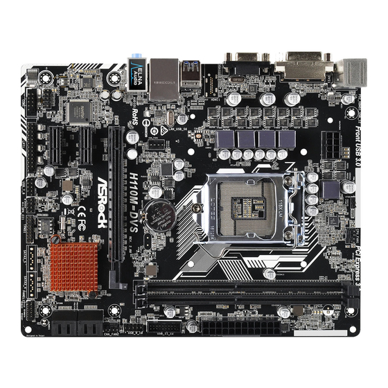
Page 11: Motherboard Layout
1.3 Motherboard Layout PCI Express 3.0 CPU_FAN1 ATX12V1 USB 3.0 T: USB3 B: USB4 Front USB 3.0 USB 2.0 CMOS CHA_FAN1 Top: T: USB5 Battery RJ-45 B: USB6 H110M-DVS RoHS PCIE1 PCIE2 Intel H110 PCIE3 HD_AUDIO1 BIOS PANEL1 CLRMOS1 COM1 PLED PWRBTN LPT1 USB_7_8... - Page 12 H110M-DVS R2.0 No. Description ATX 12V Power Connector (ATX12V1) CPU Fan Connector (CPU_FAN1) 2 x 288-pin DDR4 DIMM Slots (DDR4_A1, DDR4_B1) ATX Power Connector (ATXPWR1) USB 3.0 Header (USB_11_12) USB 2.0 Header (USB_9_10) Chassis Fan Connector (CHA_FAN2) SATA3 Connector (SATA3_0)
-
Page 13: I/O Panel
1.4 I/O Panel No. Description No. Description USB 2.0 Ports (USB_12)*** USB 2.0 Ports (USB_56)*** LAN RJ-45 Port* USB 3.0 Ports (USB_34)*** Line In (Light Blue)** D-Sub Port Front Speaker (Lime)** DVI-D Port Microphone (Pink)** PS/2 Keyboard/Mouse Port * There are two LEDs on the LAN port. Please refer to the table below for the LAN port LED indications. ACT/LINK LED SPEED LED LAN Port... - Page 14 H110M-DVS R2.0 ** To configure 7.1 CH HD Audio, it is required to use an HD front panel audio module and enable the multi- channel audio feature through the audio driver. Please set Speaker Configuration to “7.1 Speaker”in the Realtek HD Audio Manager.
-
Page 15: Chapter 2 Installation
Chapter 2 Installation This is a Micro ATX form factor motherboard. Before you install the motherboard, study the configuration of your chassis to ensure that the motherboard fits into it. Pre-installation Precautions Take note of the following precautions before you install motherboard components or change any motherboard settings. -
Page 16: Installing The Cpu
H110M-DVS R2.0 2.1 Installing the CPU 1. Before you insert the 1151-Pin CPU into the socket, please check if the PnP cap is on the socket, if the CPU surface is unclean, or if there are any bent pins in the socket. - Page 18 H110M-DVS R2.0 Please save and replace the cover if the processor is removed. The cover must be placed if you wish to return the motherboard for after service.
-
Page 19: Installing The Cpu Fan And Heatsink
2.2 Installing the CPU Fan and Heatsink... -
Page 20: Installing Memory Modules (Dimm)
H110M-DVS R2.0 2.3 Installing Memory Modules (DIMM) This motherboard provides two 288-pin DDR4 (Double Data Rate 4) DIMM slots, and supports Dual Channel Memory Technology. 1. For dual channel configuration, you always need to install identical (the same brand, speed, size and chip-type) DDR4 DIMM pairs. -
Page 22: Expansion Slots (Pci Express Slots)
H110M-DVS R2.0 2.4 Expansion Slots (PCI Express Slots) There are 3 PCI Express slots on the motherboard. Before installing an expansion card, please make sure that the power supply is switched off or the power cord is unplugged. Please read the documentation of the expansion card and make necessary hardware settings for the card before you start the installation. -
Page 23: Onboard Headers And Connectors
2.5 Onboard Headers and Connectors Onboard headers and connectors are NOT jumpers. Do NOT place jumper caps over these headers and connectors. Placing jumper caps over the headers and connectors will cause permanent damage to the motherboard. System Panel Header Connect the power PLED+ PLED-... - Page 24 H110M-DVS R2.0 Chassis Intrusion and Please connect the SPEAKER DUMMY Speaker Header chassis intrusion and the DUMMY (7-pin SPK_CI1) chassis speaker to this (see p.6, No. 14) header. SIGNAL DUMMY Serial ATA3 Connectors These four SATA3 (SATA3_0: connectors support SATA see p.6, No.
- Page 25 Front Panel Audio Header This header is for PRESENCE# MIC_RET (9-pin HD_AUDIO1) connecting audio devices OUT_RET (see p.6, No. 18) to the front audio panel. OUT2_L J_SENSE OUT2_R MIC2_R MIC2_L 1. High Definition Audio supports Jack Sensing, but the panel wire on the chassis must support HDA to function correctly.
- Page 26 H110M-DVS R2.0 ATX 12V Power This motherboard pro- Connector vides an 8-pin ATX 12V (8-pin ATX12V1) power connector. To use a (see p.6, No. 1) 4-pin ATX power supply, please plug it along Pin 1 and Pin 5. Serial Port Header...
-
Page 27: Chapter 3 Software And Utilities Operation
Chapter 3 Software and Utilities Operation 3.1 Installing Drivers The Support CD that comes with the motherboard contains necessary drivers and useful utilities that enhance the motherboard’s features. Running The Support CD To begin using the support CD, insert the CD into your CD-ROM drive. The CD automatically displays the Main Menu if “AUTORUN”... -
Page 28: Asrock Live Update & App Shop
Double-click on your desktop to access ASRock Live Update & APP Shop utility. *You need to be connected to the Internet to download apps from the ASRock Live Update & APP Shop. 3.2.1 UI Overview Category Panel Hot News... -
Page 29: Apps
3.2.2 Apps When the "Apps" tab is selected, you will see all the available apps on screen for you to download. Installing an App Step 1 Find the app you want to install. The most recommended app appears on the left side of the screen. The other various apps are shown on the right. - Page 30 H110M-DVS R2.0 Step 3 If you want to install the app, click on the red icon to start downloading. Step 4 When installation completes, you can find the green "Installed" icon appears on the upper right corner. To uninstall it, simply click on the trash can icon...
- Page 31 Upgrading an App You can only upgrade the apps you have already installed. When there is an available new version for your app, you will find the mark of "New Version" appears below the installed app icon. Step 1 Click on the app icon to see more details. Step 2 Click on the yellow icon to start upgrading.
-
Page 32: Bios & Drivers
H110M-DVS R2.0 3.2.3 BIOS & Drivers Installing BIOS or Drivers When the "BIOS & Drivers" tab is selected, you will see a list of recommended or critical updates for the BIOS or drivers. Please update them all soon. Step 1 Please check the item information before update. -
Page 33: Setting
3.2.4 Setting In the "Setting" page, you can change the language, select the server location, and determine if you want to automatically run the ASRock Live Update & APP Shop on Windows startup. -
Page 34: Enabling Usb Ports For Windows® 7 Installation
Intel® USB 3.0 eXtensible Host Controller (xHCI) drivers packed into the ISO file. Requirements A Windows® 7 installation disk or USB drive • USB 3.0 drivers (included in the ASRock Support CD or website) • A Windows® PC • Win7 USB Patcher (included in the ASRock Support CD or website) •... - Page 35 Select the “Win7 Folder” from Step1 by clicking the red circle as shown as the picture below. Step 4 Select the “USB Driver Folder” by clicking the red circle as shown as the picture below. If you are using ASRock’s Support CD for the USB 3.0 driver, please select your CD-ROM.
- Page 36 H110M-DVS R2.0 Step 5 Select where to save the ISO file by pressing the red circle as shown as the picture below. Step 6 If you want to burn the patched image to a CD, please check “Burn Image” and select “Target Device to Burn”.
-
Page 37: Chapter 4 Uefi Setup Utility
Chapter 4 UEFI SETUP UTILITY 4.1 Introduction This section explains how to use the UEFI SETUP UTILITY to configure your system. You may run the UEFI SETUP UTILITY by pressing <F2> or <Del> right after you power on the computer, otherwise, the Power-On-Self-Test (POST) will continue with its test routines. -
Page 38: Ez Mode
H110M-DVS R2.0 4.2 EZ Mode The EZ Mode screen appears when you enter the BIOS setup program by default. EZ mode is a dashboard which contains multiple readings of the system’s current status. You can check the most crucial information of your system, such as CPU speed, DRAM frequency, SATA information, fan speed, etc. -
Page 39: Advanced Mode
4.3 Advanced Mode The Advanced Mode provides more options to configure the BIOS settings. Refer to the following sections for the detailed configurations. To access the EZ Mode, press <F6> or click the "EZ Mode" button at the upper right corner of the screen. -
Page 40: Navigation Keys
H110M-DVS R2.0 4.3.2 Navigation Keys Use < > key or < > key to choose among the selections on the menu bar, and use < > key or < > key to move the cursor up or down to select items, then press <Enter>... -
Page 41: Main Screen
4.4 Main Screen When you enter the UEFI SETUP UTILITY, the Main screen will appear and display the system overview. My Favorite Display your collection of BIOS items. Press F5 to add/remove your favorite items. -
Page 42: Oc Tweaker Screen
H110M-DVS R2.0 4.5 OC Tweaker Screen In the OC Tweaker screen, you can set up overclocking features. Because the UEFI software is constantly being updated, the following UEFI setup screens and descriptions are for reference purpose only, and they may not exactly match what you see on your screen. - Page 43 Long Duration Maintained Configure the period of time until the CPU ratio is lowered when the Long Duration Power Limit is exceeded. Short Duration Power Limit Configure Package Power Limit 2 in watts. When the limit is exceeded, the CPU ratio will be lowered immediately.
- Page 44 H110M-DVS R2.0 Command Rate (CR) The delay between when a memory chip is selected and when the first active command can be issued. Secondary Timing Write Recovery Time (tWR) The amount of delay that must elapse after the completion of a valid write operation, before an active bank can be precharged.
- Page 45 Third Timing tREFI Configure refresh cycles at an average periodic interval. tCKE Configure the period of time the DDR4 initiates a minimum of one refresh command internally once it enters Self-Refresh mode. tRDRD_sg Configure between module read to read delay. tRDRD_dg Configure between module read to read delay.
- Page 46 H110M-DVS R2.0 tWRRD_dr Configure between module write to read delay. tWRRD_dd Configure between module write to read delay. tWRWR_sg Configure between module write to write delay. tWRWR_dg Configure between module write to write delay. tWRWR_dr Configure between module write to write delay.
- Page 47 Configure tXP. tXPDLL Configure tXPDLL. tPRPDEN Configure tPRPDEN. tRDPDEN Configure tRDPDEN. twRPDEN Configure twRPDEN. OREF_RI Configure OREF_RI. tREFIx9 Configure tREFIx9. txSDLL Configure txSDLL. txs_offset Configure txs_offset. tZQOPER Configure tZQOPER. tMOD Configure tMOD. ZQCS_period Configure ZQCS_period. tZQCS Configure tZQCS.
- Page 48 H110M-DVS R2.0 Advanced Setting ODT WR (CH A) Configure the memory on die termination resistors' WR for channel A. ODT WR (CH B) Configure the memory on die termination resistors' WR for channel B. ODT PARK (CH A) Configure the memory on die termination resistors' PARK for channel A.
- Page 49 Save User Default Type a profile name and press enter to save your settings as user default. Load User Default Load previously saved user defaults.
-
Page 50: Advanced Screen
H110M-DVS R2.0 4.6 Advanced Screen In this section, you may set the configurations for the following items: CPU Configuration, Chipset Configuration, Storage Configuration, Super IO Configura- tion, ACPI Configuration, USB Configuration and Trusted Computing. Setting wrong values in this section may cause the system to malfunction. -
Page 51: Cpu Configuration
4.6.1 CPU Configuration Intel Hyper Threading Technology Intel Hyper Threading Technology allows multiple threads to run on each core, so that the overall performance on threaded software is improved. Active Processor Cores Select the number of cores to enable in each processor package. CPU C States Support Enable CPU C States Support for power saving. - Page 52 H110M-DVS R2.0 Package C State Support Enable CPU, PCIe, Memory, Graphics C State Support for power saving. CPU Thermal Throttling Enable CPU internal thermal control mechanisms to keep the CPU from overheat- ing. No-Execute Memory Protection Processors with No-Execution Memory Protection Technology may prevent certain classes of malicious buffer overflow attacks.
-
Page 53: Chipset Configuration
4.6.2 Chipset Configuration Primary Graphics Adapter Select a primary VGA. Top Of Lower Usable Dram Maximum Value of TOLUD. Dynamic assignment would adjust TOLUD automatically based on largest MMIO length of installed graphic controller. VT-d Intel® Virtualization Technology for Directed I/O helps your virtual machine monitor better utilize hardware by improving application compatibility and reliability, and providing additional levels of manageability, security, isolation, and I/O performance. - Page 54 H110M-DVS R2.0 DMI ASPM Support This option enables/disables the control of ASPM on CPU side of the DMI Link. PCH DMI ASPM Support This option enables/disables the ASPM support for all PCH DMI devices. IOAPIC 24-119 Entries I/O APICs contain a redirection table, which is used to route the interrupts it receives from peripheral buses to one or more local APICs.
-
Page 55: Storage Configuration
4.6.3 Storage Configuration SATA Controller(s) Enable/disable the SATA controllers. SATA Aggressive Link Power Management SATA Aggressive Link Power Management allows SATA devices to enter a low power state during periods of inactivity to save power. It is only supported by AHCI mode. -
Page 56: Super Io Configuration
H110M-DVS R2.0 4.6.4 Super IO Configuration Serial Port 0 Enable or disable the Serial port. Serial Port Address Select the address of the Serial port. Parallel Port Enable or disable the Parallel port. Change Settings Select the address of the Parallel port. -
Page 57: Acpi Configuration
4.6.5 ACPI Configuration Suspend to RAM Select disable for ACPI suspend type S1. It is recommended to select auto for ACPI S3 power saving. ACPI HEPT Table Enable the High Precision Event Timer for better performance. PS/2 Keyboard Power On Allow the system to be waked up by a PS/2 Keyboard. - Page 58 H110M-DVS R2.0 USB Mouse Power On Allow the system to be waked up by an USB mouse.
-
Page 59: Usb Configuration
4.6.6 USB Configuration Legacy USB Support Enable or disable Legacy OS Support for USB 2.0 devices. If you encounter USB compatibility issues it is recommended to disable legacy USB support. Select UEFI Setup Only to support USB devices under the UEFI setup and Windows/Linux operating systems only. -
Page 60: Trusted Computing
H110M-DVS R2.0 4.6.7 Trusted Computing Security Device Support Enable or disable BIOS support for security device. -
Page 61: Tools
In order to prevent users from bypassing OMG, guest accounts without permission to modify the system time are required. UEFI Tech Service Contact ASRock Tech Service if you are having trouble with your PC. Please setup network configuration before using UEFI Tech Service. Easy Driver Installer For users that don’t have an optical disk drive to install the drivers from our support... - Page 62 Save UEFI files in your USB storage device and run Instant Flash to update your UEFI. Internet Flash - DHCP (Auto IP), Auto ASRock Internet Flash downloads and updates the latest UEFI firmware version from our servers for you. Please setup network configuration before using Internet Flash.
- Page 63 Network Configuration Use this to configure internet connection settings for Internet Flash. Internet Setting Enable or disable sound effects in the setup utility. UEFI Download Server Select a server to download the UEFI firmware.
-
Page 64: Hardware Health Event Monitoring Screen
H110M-DVS R2.0 4.8 Hardware Health Event Monitoring Screen This section allows you to monitor the status of the hardware on your system, including the parameters of the CPU temperature, motherboard temperature, fan speed and voltage. Fan-Tastic Tuning Select a fan mode for CPU Fan 1, or choose Customize to set 5 CPU temperatures and assign a respective fan speed for each temperature. - Page 65 Chassis Fan 2 Temp Source Select a fan temperature source for Chassis Fan 2. Over Temperature Protection When Over Temperature Protection is enabled, the system automatically shuts down when the motherboard is overheated. Case Open Feature Enable or disable Case Open Feature to detect whether the chassis cover has been removed.
-
Page 66: Security Screen
H110M-DVS R2.0 4.9 Security Screen In this section you may set or change the supervisor/user password for the system. You may also clear the user password. Supervisor Password Set or change the password for the administrator account. Only the administrator has authority to change the settings in the UEFI Setup Utility. -
Page 67: Boot Screen
4.10 Boot Screen This section displays the available devices on your system for you to configure the boot settings and the boot priority. Fast Boot Fast Boot minimizes your computer's boot time. In fast mode you may not boot from an USB storage device. Ultra Fast mode is only supported by Windows 8.1 and the VBIOS must support UEFI GOP if you are using an external graphics card. - Page 68 H110M-DVS R2.0 Full Screen Logo Enable to display the boot logo or disable to show normal POST messages. AddOn ROM Display Enable AddOn ROM Display to see the AddOn ROM messages or configure the AddOn ROM if you've enabled Full Screen Logo. Disable for faster boot speed.
- Page 69 CSM (Compatibility Support Module) Enable to launch the Compatibility Support Module. Please do not disable unless you’re running a WHCK test. If you are using Windows 8.1 64-bit and all of your devices support UEFI, you may also disable CSM for faster boot speed. Launch PXE OpROM Policy Select UEFI only to run those that support UEFI option ROM only.
-
Page 70: Exit Screen
H110M-DVS R2.0 4.11 Exit Screen Save Changes and Exit When you select this option the following message, “Save configuration changes and exit setup?” will pop out. Select [OK] to save changes and exit the UEFI SETUP UTILITY. Discard Changes and Exit When you select this option the following message, “Discard changes and exit... - Page 71 Contact Information If you need to contact ASRock or want to know more about ASRock, you’re welcome to visit ASRock’s website at http://www.asrock.com; or you may contact your dealer for further information. For technical questions, please submit a support request form at http://www.asrock.com/support/tsd.asp...