Advertisement
Quick Links
QQ
3 7 63 1515 0
TE
L 13942296513
www
.
PA
011489
20000125-85000
http://www.xiaoyu163.com
CONTENTS
SPECIFICATIONS
DIMENSIONS
PANEL LAYOUT
CIRCUIT BOARD LAYOUT
BLOCK DIAGRAM
DISASSEMBLY PROCEDURE
CIRCUIT BOARD
INSPECTIONS
OVERALL CIRCUIT DIAGRAM
x
ao
u163
PARTS LIST
y
i
http://www.xiaoyu163.com
2 9
8
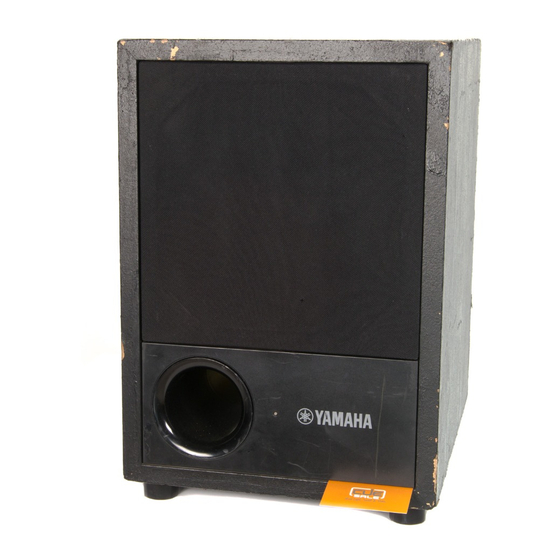
SW10
SERVICE MANUAL
Q Q
3
6 7
1 3
1 5
............................................................ 3
......................................................... 8/10
co
.
9 4
2 8
0 5
8
2 9
9 4
2 8
................................................. 3
..................................... 4
................. 4
................................ 4
............................. 5
........................................... 6
m
HAMAMATSU, JAPAN
0.29K-5531
Printed in Japan '99.12
SW10
9 9
9 9
1
Advertisement

Related Manuals for Yamaha SW10


Summary of Contents for Yamaha SW10
- Page 1 SW10 3 7 63 1515 0 SW10 SERVICE MANUAL L 13942296513 CONTENTS SPECIFICATIONS ..........3 DIMENSIONS ............3 PANEL LAYOUT ........4 CIRCUIT BOARD LAYOUT ....4 BLOCK DIAGRAM ........ 4 DISASSEMBLY PROCEDURE ......5 CIRCUIT BOARD ........... 6 INSPECTIONS ............
- Page 2 IMPOR TANT NOTICE This manual has been provided for the use of authorized Yamaha Retailers and their service personnel. It has been assumed that basic service procedures inherent to the industry, and ÏWre specifically Yamaha Products, are already known and under- stood by the users, and have therefore not been restated.
- Page 3 SW10 3 7 6 3 1 5 1 5 0 SPECIFICATIONS General specifications Type........... Bass Reflex Powered Speaker Frequency Range ....... 25–150 Hz (–10 dB) Sensitivity ........–12 dB at Vol. Max (for 100 dB/SPL, 1 m on Axis) Maximum Output Level .....
-
Page 4: Table Of Contents
SW10 3 7 6 3 1 5 1 5 0 PANEL LAYOUT CIRCUIT BOARD LAYOUT Front panel Power/Clip indicator PHASE switch CUTOFF FREQ control VOL (Volume) control INPUT jacks 1, 2, and 3 MAIN 1/5 OUTPUT jacks 1, 2, and 3... -
Page 5: Front Panel
SW10 3 7 6 3 1 5 1 5 0 DISASSEMBLY PROCEDURE [140] [170] [130] Woofer Remove the front grille. 1-2. Remove the eight (8) screws marked [140]. The woofer can then be removed. (Fig.1) Control Panel [130] Remove the four (4) screws marked [170]. The [140] control panel can then be removed. -
Page 6: T E
SW10 3 7 6 3 1 5 1 5 0 CIRCUIT BOARD MAIN Circuit Board MAIN 1/5 MAIN 3/5 INPUT OUTPUT VOL. CN505: to Transformer (AC2) CN301: to CN502: to CUTOFF MA2/5-CN401 MA2/5-CN202 FREQ. CN501: to MA5/5-CN604 K401,K301: to... -
Page 7: Ao Y
SW10 3 7 63 1515 0 MAIN 2/5 MAIN 4/5 CN201: to CN401: to MA1/5-CN101 MA3/5-CN301 CN602: to Power SW. CN601: to Transformer L 13942296513 CN603: to AC IN CN202: to Component side MA3/5-CN502 Component side u163 MAIN: 3NA-V434520... - Page 8 SW10 3 7 63 1515 0 INSPECTIONS Measuring Instruments oscillator, oscilloscope, level meter, noise meter (with an IHF-A filter) Preparation Load resistance setting: Between speaker terminals K301 and 401 RL=8 ohm (non-conductive resistance of 250 W or more power) Knob settings: VOL.:...
-
Page 9: Input
SW10 3 7 63 1515 0 7. Frequency Response Use the output level at the speaker terminal when a 30 Hz signal is input as “0”. When the F control VR is adjusted, check that the frequency response is as shown in the following table:... - Page 10 SW10 3 7 63 1515 0 L 13942296513 u163 http://www.xiaoyu163.com...
- Page 11 SW10 3 7 63 1515 0 L 13942296513 u163 http://www.xiaoyu163.com...
-
Page 12: Parts List
3 7 63 1515 0 SW10 PARTS LIST CONTENTS OVERALL ASSEMBLY ..........2 ELECTRICAL PARTS ..........4 L 13942296513 Notes : DESTINATION ABBREVIATIONS A : Australian model M : South African model B : British model O : Chinese model... - Page 13 SW10 3 7 63 1515 0 OVERALL ASSEMBLY A170 A110 A50a A130 A50b A140 A150 A100 R80a A50c A160 L 13942296513 A140 A50d A120 A50e u163 http://www.xiaoyu163.com...
- Page 14 SW10 3 7 63 1515 0 PART NO. DESCRIPTION REMARKS REF NO. RANK OVERALL ASSEMBLY SW10 Overall Assembly (V436470) Overall Assembly U, V (V436480) Overall Assembly H, W (V436490) Overall Assembly (V436500) Overall Assembly (V436510) V 4 3 6 5 6 0 0...
- Page 15 SW10 3 7 63 1515 0 ELECTRICAL PARTS PART NO. DESCRIPTION REMARKS REF NO. RANK ELECTRICAL PARTS SW10 AAX08780 Circuit Board MAIN 1/5 (XW549C0) AAX08790 Circuit Board MAIN 2/5 (XW549C0) AAX08800 Circuit Board MAIN 3/5 (XW549C0) AAX08810 Circuit Board...
- Page 16 SW10 3 7 63 1515 0 PART NO. DESCRIPTION REMARKS REF NO. RANK Q309 VR152800 Transistor 2SA1480 E,F Q310 I C 2 2 4 0 3 0 Transistor 2SC2240 GR,BL Q351 VQ547300 Transistor 2SC4793 (HFE) Q352 VR152900 Transistor 2SC3790 E,F...
- Page 17 SW10 3 7 63 1515 0 PART NO. DESCRIPTION REMARKS REF NO. RANK V 2 7 2 8 8 0 0 Electrolytic Cap.-VX 50.0V C:133,149,150,203 V 4 2 4 5 5 0 0 Electrolytic Cap. 10000 63.0V C:511,512 FU451220...
- Page 18 http://www.xiaoyu163.com SW-10 OVERALL CIRCUIT DIAGRAM SW-10 3 7 6 3 1 5 1 5 0 1 3 9 4 2 2 9 6 5 1 3 w w w u 1 6 3 http://www.xiaoyu163.com...