Advertisement
Safe Operation Practices • Set-Up • Operation • Service • Troubleshooting
O
Table of Contents
Safe Operation Practices ........................................ 2
Assembly & Set-Up .................................................. 5
Controls & Operation .............................................. 8
READ AND FOLLOW ALL SAFETY RULES AND INSTRUCTIONS IN THIS MANUAL
FAILURE TO COMPLY WITH THESE INSTRUCTIONS MAY RESULT IN PERSONAL INJURY.
NOTE: This Operator's Manual covers several models. Features may vary by model. Not all features in this manual are applicable to all
models and the model depicted may differ from yours.
Printed In USA
peratOr
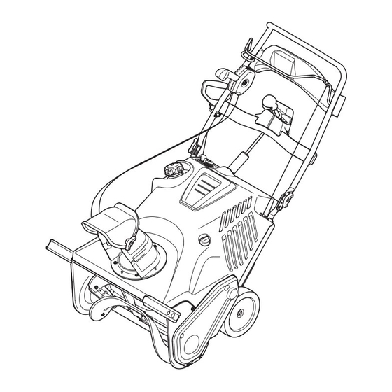
Snow Thrower
BEFORE ATTEMPTING TO OPERATE THIS MACHINE.
'
M
s
Single-Stage
(200 Series)
Service .....................................................................10
Troubleshooting .....................................................12
Parts/Warranty .............. See Separate Supplement
WARNING
anual
Form No. 769-10790
(May 20, 2015)
Advertisement
Table of Contents

Related Manuals for Remington RM2100


Summary of Contents for Remington RM2100
-
Page 1: Table Of Contents
Safe Operation Practices • Set-Up • Operation • Service • Troubleshooting ’ peratOr anual Snow Thrower Single-Stage (200 Series) Table of Contents Safe Operation Practices ........2 Service ..............10 Assembly & Set-Up ..........5 Troubleshooting .............12 Controls & Operation ..........8 Parts/Warranty .... -
Page 2: Important Safe Operation Practices
Important Safe Operation Practices WARNING! This symbol points out important safety instructions which, if not followed, could endanger the personal safety and/or property of yourself and others. Read and follow all instructions in this manual before attempting to operate this machine. Failure to comply with these instructions may result in personal injury. - Page 3 Plan your snow-throwing pattern to avoid discharge towards Snow thrower shave plates and skid shoes are subject to wear windows, walls, cars etc. Thus, avoiding possible property damage and damage. For your safety protection, frequently check all or personal injury caused by a ricochet. components and replace with original equipment manufacturer’s (OEM) parts only.
-
Page 4: Safety Symbols
Safety Symbols This page depicts and describes safety symbols that may appear on this product. Read, understand, and follow all instructions on the machine before attempting to assemble and operate. Symbol Description READ THE OPERATOR’S MANUAL(S) Read, understand, and follow all instructions in the manual(s) before attempting to assemble and operate. WARNING —... -
Page 5: Assembly & Set-Up
Assembly & Set-Up Thank You Thank you for purchasing this product. It was carefully engineered to If applicable, the power testing information used to establish the power rating provide excellent performance when properly operated and maintained. of the engine equipped on this machine can be found at www.opei.org or the engine manufacturer’s web site. -
Page 6: Handle Assembly
Tools Required On models with adjustable handles, Align the holes in the chute base with the three tabs (b) in the lower chute as place the handle in the desired position and then install wing knobs (a) and shown in Figure 2-8, Inset I. Secure the •... - Page 7 Installing the Chute Rotation Installing the Recoil Starter Using the hex washer screws (a), install the chute rotation control assembly. See Control (If Equipped) Handle onto the Upper Handle Figure 2-12. NOTE: Remove the eye bolt and handle knob Refer to Figure 2-1 and continue to your from the manual bag.
-
Page 8: Controls & Operation
Controls & Operation Upper 2-Way Chute † Headlight † Auger Control Lever Chute Tilt Control † Chute Tilt Control Recoil Starter Handle Chute Rotation Control Chute Rotation Control † Chute Assembly Lower 2-Way Chute † (See Insets for Specific Chute Types) Chute Rotation E-Z Chute™... -
Page 9: Choke Lever
Choke Lever Engaging the Drive Upper 2-Way Chute (If Equipped) Activating the choke control closes the choke To increase the angle/distance snow is thrown, Lift up slightly on the handle to allow the plate on carburetor and aids in starting engine. pull up/back on the chute tilt control (a). -
Page 10: Service
Service WARNING! NOTE: An oil drain extension kit is Tip the snow thrower back to the Before servicing, available separately. Contact your local operating position and pull the recoil repairing or inspecting the snow authorized dealer or contact Customer starter handle a few times to see if it is thrower, disengage the auger Support. - Page 11 Replacing Shave Plate Remove the belt cover by removing the Squeeze the auger control lever against two hex washer screws (a) and one hex the upper handle and reinstall the belt lock screw (b) that secure it to the frame. cover removed in Step 4.
-
Page 12: Troubleshooting
Troubleshooting Problem Cause Remedy Engine fails to start 1. Choke not in CHOKE position. 1. Move choke to CHOKE position. See Engine Operator’s Manual. 2. Spark plug wire disconnected. 2. Connect wire to spark plug. See Engine Operator’s Manual 3. Fuel tank empty or stale fuel. 3.