Advertisement
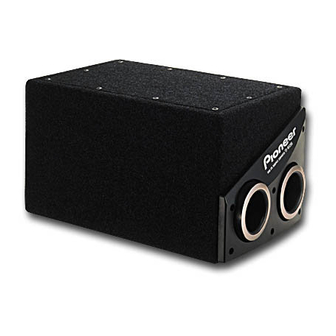
AMPLIFIED BANDPASS SUBWOOFER
TS-WX205A
1. SPECIFICATIONS
• Speaker specifications
Size ............................................................... φ 200mm (8" Dia.)
• Amplifier
Max. Power output ............................ 100W (65Hz, 22% THD)
DIN output power (DIN45324, 65Hz, 1.8Ω+B=14.4V) .... 70W
INPUT LEVEL (at Gain Max)
(RCA) ............................................. 100mV+100mV/20kΩ
(Speaker line) .................................................. 2V+2V/5kΩ
Power source ....................... DC14.4V (10.8~15.6V allowable)
Max. current consumption .................................................... 9A
Grounding ....................................................... Negative ground
• Speaker system ...................................................... Bandpass type
• Cabinet material ..................................................... Particle board
• Sensitivity ....................................... 107dB/W (In car, SUV type)
• Size ...............................................................................................
..... 474mm(18-5/8")(W)×280mm(11")(D)×248mm(9-3/4")(H)
• Weight (including accessory parts) ................. 10.1kg (22lb 4oz)
• Gross weight (including packaging) ............... 11.5kg (25lb 6oz)
Note:
Specifications and the design are subject to possible modification
without notice due to improvements.
PIONEER ELECTRONIC CORPORATION
PIONEER ELECTRONICS SERVICE, INC. P.O. Box 1760, Long Beach, CA 90801-1760, U.S.A.
PIONEER ELECTRONIC (EUROPE) N.V. Haven 1087, Keetberglaan 1, 9120 Melsele, Belgium
PIONEER ELECTRONICS ASIACENTRE PTE. LTD. 253 Alexandra Road, #04-01, Singapore 159936
c
PIONEER ELECTRONIC CORPORATION 1999
High compliance, rolled edge
Heat-resistant voice coil
Strontium magnet : 500g (18oz)
4-1, Meguro 1-Chome, Meguro-ku, Tokyo 153-8654, Japan
2. HOW TO INSTALL
Iron plate
Backle
Belt end
H – IZX JUNE 1999 Printed in Japan
ORDER NO.
TRT1124
EW
Advertisement
Table of Contents

Related Manuals for Pioneer TS-WX205A


Summary of Contents for Pioneer TS-WX205A
- Page 1 PIONEER ELECTRONIC CORPORATION 4-1, Meguro 1-Chome, Meguro-ku, Tokyo 153-8654, Japan PIONEER ELECTRONICS SERVICE, INC. P.O. Box 1760, Long Beach, CA 90801-1760, U.S.A. PIONEER ELECTRONIC (EUROPE) N.V. Haven 1087, Keetberglaan 1, 9120 Melsele, Belgium PIONEER ELECTRONICS ASIACENTRE PTE. LTD. 253 Alexandra Road, #04-01, Singapore 159936 PIONEER ELECTRONIC CORPORATION 1999 H –...
-
Page 2: Exploded Views And Parts List
TS-WX205A 3. EXPLODED VIEWS AND PARTS LIST • NOTES: Parts marked by "NSP" are generally unavailable because they are not in our Master Spare Parts List. • mark found on some component parts indicates the importance of the safety factor of the part. -
Page 3: Packing Parts List
TS-WX205A 3.2 PACKING PARTS LIST Mark No. Description Part No. Remark PARTS INCLUDED ×1 Parts Bag TEA1272 ×8 1-1 Screw BNC40P250FZK ×4 1-2 Fitting Metal TNA1220 ×8 ×2 Belt Assy TXH1420 ×4 ×1 Cord Poly. Assy TXH1558 ×1 3-1 Cord TDC2259 ×1... -
Page 4: Schematic Diagram
TS-WX205A 4. PCB UNIT(TWX1025-AZ) 4.1 SCHEMATIC DIAGRAM AMP UNIT (TWK1010) SWITCH UNIT (TWS1028) C107 100p ISOLATOR C103 R107 2.2/50 R103 CN205 (NP) TP201 R109 CN201 CN101 TP202 TP212 TP101 R101 IC101 TP203 C101 RCA INPUT (2/2) 2.2/50 C105 TP213 TP102... - Page 5 TS-WX205A Note : When ordering service parts, be sure to refer to "EXPLODED VIEWS and PARTS LIST" or "PCB PARTS LIST". : AUDIO SIGNAL ROUTE BUFFER C110 100p C109 MIXER 100p CN105 TP120 TP121 R119 R116 SP UNIT R111 R113...
-
Page 6: Pcb Connection Diagram
TS-WX205A 4.2 PCB CONNECTION DIAGRAM AMP UNIT Q152 Q172 IC103 IC103 Q171 Q179 Q174 Q176 Q175 Q177 Q178 IC102 IC102 R110 C106 R106 IC101 Q173 IC101 R102 R108 C107 C108 R107 IC131 C103 R103 CN101 CN103 SP UNIT SWITCH UNIT... - Page 7 TS-WX205A AMP UNIT TP111 TP110 TP109 TP108 TP107 TP106 TP115 TP118 TP119 TP120 TP121 SWITCH UNIT TP214 TP215 TP201 TP204 TP216 TP202 TP217 TP203 TP218 TP219 TP220 TP221 TP222 TP208 TP223 TP205 TP207 TP206 TP209 TP210 TP210 • This diagram is viewed from the foil side.
-
Page 8: Pcb Parts List
TS-WX205A 5. PCB PARTS LIST • NOTES: Parts marked by "NSP" are generally unavailable because they are not in our Master Spare Parts List. • mark found on some component parts indicates the importance of the safety factor of the part. - Page 9 TS-WX205A 5. CONNECTIONS Wiring Example 1 (Speaker line Input system) Connect all the other leads, and finally connect this terminal to the positive (+) terminal of the battery. Speaker For ground Speaker Connect firmly to a metal part of the car body.
- Page 10 TS-WX205A Wiring Example 2 (RCA Input system) Connect all the other leads, and finally connect this terminal to the positive (+) terminal of the battery. Speaker Power amplifier RCA cord (Not included) For ground Connect firmly to a metal part of the car body.