Table of Contents
Advertisement
Quick Links
Advertisement
Table of Contents

Related Manuals for Eneo PNR-5104


Summary of Contents for Eneo PNR-5104
-
Page 3: Compliance Notice Of Fcc
Network Video Recorder WARNING RISK OF ELECTRIC SHOCK DO NOT OPEN WARNING: TO REDUCE THE RISK OF ELECTRIC SHOCK, DO NOT REMOVE COVER (OR BACK). NO USER-SERVICEABLE PARTS INSIDE. REFER SERVICING TO QUALIFIED SERVICE PERSONNEL. The lightning flash with arrowhead symbol, within an equilateral triangle, is intended to alert the user to the presence of uninsulated "dangerous voltage"... -
Page 4: Operating Instructions
Operating Instructions Important Safeguards 1. Read Instructions 11. Overloading All the safety and operating instructions should be read before the Do not overload wall outlets and extension cords as this can result appliance is operated. in the risk of fire or electric shock. 2. -
Page 5: Table Of Contents
Network Video Recorder Table of Contents Chapter 1 — Introduction .................... 1 1.1 Features ......................1 1.2 System Diagram ....................2 1.3 Rear Panel ......................2 Factory Reset ....................3 1.4 Front Panel ......................3 1.5 Tuning On/Off the System ................. 3 Chapter 2 —... - Page 6 Operating Instructions Layout Monitoring.................... 44 Layout Sequence Monitoring ................46 Camera Sequence Monitoring ................ 48 5.2 Map Monitoring....................49 5.3 Controlling Cameras ..................51 PTZ Control ..................... 52 Zoom Control ....................53 5.4 Controlling Maps ..................... 54 Chapter 6 — Recording ..................... 56 6.1 Setting up Recording Schedule...............
- Page 7 Network Video Recorder Chapter 13 — User Management ................102 Chapter 14 — Storage Management ..............104 Chapter 15 — Event Management ................108 15.1 Setting up Event Management Schedule ............ 108 Managing Schedule ..................113 15.2 Managing Events ..................115 Live Popup ....................
- Page 8 Operating Instructions...
-
Page 9: Chapter 1 - Introduction
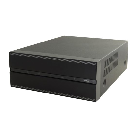
Network Video Recorder Chapter 1 — Introduction This manual describes installation and operation of Network Video Recorder (NVR), which is designed to be used with network cameras, network video transmitters and DVRs. 1.1 Features This network video recorder provides monitoring of video from network video transmitters, network cameras and DVRs, recording of monitoring video (DVR excluded) and playback of video recorded in the NVR system or DVR. -
Page 10: System Diagram
Operating Instructions NOTES: This product includes software developed by the OpenSSL Project for use in the OpenSSL Toolkit (http://www.openssl.org/). The software included in this product contains some Open Sources. You may obtain the complete corresponding source code from us. See the Open Source Guide on the software CD (OpenSourceGuide\ OpenSourceGuide.pdf) or as a printed document included along with the User's Manual. -
Page 11: Factory Reset
Network Video Recorder ⑤ Factory Reset Switch: Use to return all settings except device related settings to the original factory settings. See below for details. NOTES: Do NOT connect or disconnect eSATA devices while the NVR power is on. The NVR must be powered down to connect or disconnect eSATA devices. -
Page 12: Chapter 2 - Installation
Operating Instructions Chapter 2 — Installation You can connect the NVR system remotely only via network connection. This requires installing the following programs in your PC. INIT Program: Allows you to set up network information of the NVR system for remote connection. ... -
Page 13: Installation
Network Video Recorder VGA: ATI RadeonTM HD 3650 or NVIDIA GeForce 8400GS (ATI recommended) (1024x768, 24bpp or higher) Hard Disk Drive: 350 MB or more free space LAN: Gigabit Ethernet or faster Minimum System Requirements Operating System: Microsoft ®... - Page 14 Operating Instructions 4. When the following screen appears, click Next. 5. Designate the folder path to install the Client program. Clicking the Disk Cost… button shows the available and required disk space for each hard disk drive for the installation. Then click Next.
-
Page 15: Uninstall
Network Video Recorder NOTE: The following screen appears when the port number of the service being installed is already in use, and the screen displays the port number that will be changed. The changed port number will be applied when the service starts operating after installation. - Page 16 Operating Instructions 4. Click the Remove All or Do not remove button when the following screen appears. Clicking the Remove All button deletes all saved data including recorded video and previous settings in the system. Clicking the Do not remove button uninstalls the software without deleting any saved data in the system and keeps all saved data in the system.
-
Page 17: Chapter 3 - Getting Started
Network Video Recorder Chapter 3 — Getting Started NOTE: In this manual, the “server or server system” refers to a PC on which a iNEX service is running, the “client system” refers to a PC on which the Client program is running and the “network video device” refers to a network video transmitter or network camera. -
Page 18: System Setup
Operating Instructions Site Name: Select the NVR system to connect to from the list. If you connect to the NVR system for the first time, click the button at the right, select Add or Modify and enter network information of the NVR system to connect −... - Page 19 Network Video Recorder Date, Time, Time Zone: Displays the date, time and time zone of the NVR system. Time Sync − Automatic Sync: Automatically synchronizes the time with a time server. Enter the IP address or the domain name of the time server and set the time interval for synchronization.
- Page 20 Operating Instructions DVRNS Server Address, Server Port: Enter the IP address (domain name) and port number of the DVRNS server to register the NVR system. Use DVRNS: Allows you to enter the name instead of the IP address of the NVR system by using the DVRNS function when connecting to the NVR system.
-
Page 21: Registering Devices
Network Video Recorder 3.2 Registering Devices You must register devices on the NVR system and add the devices to a device group in order to perform any operation. Run the Setup program. Refer to 3.1 Connecting (p. 11) for details about running the Setup program. 1. - Page 22 Operating Instructions Protocol: Select the protocol or manufacturer of the device to scan. Event related functions may not be supported depending on the protocol that the device uses (supported for the iNEX protocol and some versions of the ONVIF Conformance and Axis protocol), and some other functions may not be supported depending on the settings of the device.
- Page 23 Network Video Recorder NOTES: Depending on the model, the device may not be supported even though the iNEX program supports the device's protocol. Ask your dealer or distributor about supported models. If the device uses the ONVIF Conformance protocol, you can select either the manufacturer (or iNEX protocol) or the ONVIF Conformance protocol.
- Page 24 Operating Instructions NOTES: If the device is a DVR, it might be necessary to enter the DVR port numbers depending on the specifications and version of the DVR. When registering a four-channel network video transmitter which uses the iNEX protocol, all four cameras are automatically registered even if some of the four cameras are disabled.
-
Page 25: Live Video Monitoring
Network Video Recorder Selecting the registered device group, and then the button at the bottom of the Site List panel displays the Edit Device Group window and allows you to edit the selected device group. Refer to Chapter 12 — Device Management (p. 89) for details. 3.3 Live Video Monitoring Go to the Start Menu →... -
Page 26: Allocating Cameras
Operating Instructions Allocating Cameras button at the bottom. The Setup – Recording Service window 1. Select a recording service and click the appears. Select the Device Setup tab. The list of cameras registered on the current recording service is displayed. Clicking the Add button at the bottom allows you to register additional cameras on the current recording service. -
Page 27: Setting Up Recording Schedule
Network Video Recorder NOTE: If you remove a device for which some recording has been done and register the device again, the NVR system considers the device as a new device. In this case, you can search or play back video recorded →... -
Page 28: Playing Recorded Video
Operating Instructions 2. Double click anywhere in the empty space of each schedule window, and the Preset setup window appears. 3. Select a desired Preset from the Preset list, or click the button to add a new Preset. Selecting a Preset from the list and clicking the button deletes the selected Preset or allows you to edit the selected Preset settings. -
Page 29: Chapter 4 - System Overview
Network Video Recorder Chapter 4 — System Overview The iNEX software consists of the following programs: Service Manager: Controls the operation of services or displays system log. Refer to 4.1 Service Manager (p. 23) for details. Setup: Allows you to add service, devices and users, or set up recording schedules, event management schedules and storage. -
Page 30: Status Display
Operating Instructions Option − Server Option: Sets up the information for connection to the NVR system from the current server. Also, you can change the watchdog setting. Watchdog Tab Timeout (Min.): Set up the waiting time to restart services when services fail to operate. -
Page 31: Service Database Backup/Restore
Network Video Recorder Service Database Backup/Restore (Service Database Backup) button allows you to save the setting values related to services as an .iexp file. (Service Database Restore) button allows you to apply the saved setting values to the current NVR system. -
Page 32: Cascade
Operating Instructions button at the top right corner and select a setup file to apply → Services of the current NVR Click the system are displayed to the left of the icon. Services that are saved in the setup file are displayed to the right of the icon. - Page 33 Network Video Recorder Master NVR System Master, Slave: Select Master. It allows you to watch or search video of this NVR system and slave NVR systems (maximum 7) registered on this NVR system. The NVR system runs as a master NVR system by default and this setting will be used when the NVR system has been run as a slave NVR system and you want to change it back to a master NVR system.
-
Page 34: Setup
Operating Instructions 4.2 Setup Run the Setup program. Refer to 3.1 Connecting (p. 11) for details about running the Setup program. Service: Allows you to register and manage services and storage. Refer to Service (p. 28) for details. Device: Allows you to register and manage sites. Refer to Device (p. 29) for details. ... -
Page 35: Service
Network Video Recorder Service The Service menu allows you to register and manage services and storage. ① (Service Database Backup), (Service Database Restore): Allows you to save the setting values related to services as an .iexp file. It also, allows you to apply the saved setting values to the current NVR system. -
Page 36: Device
Operating Instructions Device The Device menu allows you to register and manage sites. ① (Multiple Firmware Upgrade): Allows you to upgrade software for several devices at the same time. Refer to 12.2 Managing Devices, Upgrading Device’s Software (p. 96) for details. ②... -
Page 37: User
Network Video Recorder ⑦ (Add), (Remove), (Edit): Allow you to add, remove and edit a device or a site. You can also delete sites from the group or to edit registration information by using the menu that is displayed when selecting a site and clicking the right mouse button. -
Page 38: Recording Schedule
Operating Instructions Recording Schedule The Recording Schedule menu allows you to set up the schedule for recording. ① Schedule Panel: Displays a registered schedule list. The iNEX program performs recording based on the schedule. ② Detailed Information Panel: Displays setting values of the selected recording schedule. ③... -
Page 39: Event Management
Network Video Recorder Event Management The Event Management menu allows you to set up event management schedules. ① Schedule Panel: Displays a registered schedule list. The iNEX program manages events based on the schedule. ② Detailed Information Panel: Displays setting values of the selected event management schedule. ③... -
Page 40: Client
Operating Instructions 4.3 Client Go to the Start Menu → Click iNEX → Run the iNEX Client program and enter login information. Refer to 3.1 Connecting, Log In (p. 11) for details about the login. ① Menu: Allows you to control the Client program. Refer to Menu (p. 35) for details. ②... -
Page 41: Menu
Network Video Recorder Menu System New Tab: Adds panels. A maximum of 12 panels are supported for Live, Play, Backup Search, DVR Search and Map panels altogether (no more than 2 of Map panels and no more than 4 of each for the other panels). -
Page 42: Site List
Operating Instructions Export Video File: Exports recorded video as a self-player file (.exe) or an AVI file (.avi). Snapshot on Motion: Displays snapshot of images recorded during the event-based recording (event and pre-event) in the Play panel. Refer to 7.1 Playing back Recorded Video, Snapshot on Motion Event (p. - Page 43 Network Video Recorder Backup Search: Not supported. DVR Search: Allows you to play back the video recorded in DVRs or SD (SDHC) memory cards inserted to network cameras using the iNEX protocol. Refer to Chapter 7 — Recorded Video Playback & Exportation (p.
-
Page 44: Menu - Preference Settings
Operating Instructions Menu – Preference Settings You can set the basic settings of the Client program to meet your preferences. Go to the System Menu → Click Preference, and the Preference window appears. System Date/Time: Displays the current date and time. ... - Page 45 Network Video Recorder Screen Display Display OSD: Sets up the OSD display setting and information to be displayed on a camera screen. The Opacity slide bar allows you to adjust the opacity of OSD (On Screen Display), OSD Magnification changes the OSD size depending on the screen size.
- Page 46 Operating Instructions Video Enhancement Aspect Ratio: Select the proper image aspect ratio. − Original Ratio: Fits images within the screen size while maintaining their original ratio. − Fit to Screen: Fits images to the screen size regardless of the aspect ratio. −...
- Page 47 Network Video Recorder Instant Event Time Range: Set up the length of time for an event notification to be displayed in the Instant Event List after notification of the event detection (If the event list has 100 or fewer items, the event list will remain on the Instant Event List even if the length of time has expired).
- Page 48 Operating Instructions Don’t display broken frames: It is possible that frames will be broken or lost when using the RTP protocol depending on the network environment. Select whether or not to display the broken frames in Live or Play panels. ...
- Page 49 Network Video Recorder User Auto run iNEX Client at Windows startup: The Client program automatically runs when logging onto Windows. Auto login at startup: The Client program automatically logs in with the login information from the previous connection when it starts. Checking the Restore last Live sessions at auto login box restores the previous live monitoring sessions in the current Live panels.
-
Page 50: Chapter 5 - Live Video Monitoring
Operating Instructions Chapter 5 — Live Video Monitoring You can monitor live video of each group. The NVR system displays video from devices based on the settings in the device on the Live screen. First, check the following and run the Client program. ... - Page 51 Network Video Recorder (Layout Sequence): Starts or stops layout sequence. Refer to 5.1 Monitoring Video, Layout Sequence Monitoring (p. 49) for details. (Hotspot): Sets up a selected camera screen as a hotspot screen. Refer to Hotspot Setup (p. 46) for details.
-
Page 52: Layout Monitoring
Operating Instructions CAM3: An event is detected. Map Event Spot Setup NOTE: The “map event spot” in the iNEX program is a predefined camera screen in which video from a camera which an event is detected among cameras on a map can be monitored with emphasis. The map event spot screen is surrounded by a gray outline. - Page 53 Network Video Recorder Registering Layouts 1. Go to the System menu, and click iNEX Setup, and select the Device menu. 2. Click Layout in the Site panel, and then the button at the bottom of the Site List panel on the right. The Add Layout window appears.
-
Page 54: Layout Sequence Monitoring
Operating Instructions Layout Sequence Monitoring You can monitor video from multiple cameras sequentially in more than one predefined layout. A layout sequence should be registered on the NVR system for layout sequence monitoring. Refer to the following for details about layout sequence registration. NOTE: A “layout”... - Page 55 Network Video Recorder Name: Enter the layout sequence name. Public/Private: Displays the layout sequence to all users (Public) or to a current user only (Private). The admin user can see all layout sequences. Owner: Displays the user ID of the person who created the layout sequence. ...
-
Page 56: Camera Sequence Monitoring
Operating Instructions Camera Sequence Monitoring You can monitor video from multiple cameras in the same camera screen sequentially. A camera sequence should be registered on the NVR system for camera sequence monitoring. Refer to the following for details about camera sequence registration. 1. -
Page 57: Map Monitoring
Network Video Recorder Name: Enter the camera sequence name. Public/Private: Displays the camera sequence to all users (Public) or to a current user only (Private). The admin user can see all camera sequences. Owner: Displays the user ID of the person who created the camera sequence. ... - Page 58 Operating Instructions Select a desired map from the Map list, and drag and drop it on the Live screen. The selected map is displayed on the screen. You can move a map to the desired location on the Live screen without disconnecting the current connection while monitoring video.
-
Page 59: Controlling Cameras
Network Video Recorder Select a desired path of the path sequence from the map, and drag and drop it on the Live screen. Video from the cameras associated to the path sequence is displayed sequentially during the preset duration period. 5.3 Controlling Cameras A control toolbar and a screen menu are provided for controlling camera. -
Page 60: Ptz Control
Operating Instructions PTZ Control, Color Control, Image Zoom, Listen, Talk, Instant Recording: These function the same as clicking the individual buttons on the control toolbar. Refer to Control Toolbar (p. 54) for details. Audio Broadcast: Broadcasts audio to each device in the current Live tab. ... -
Page 61: Zoom Control
Network Video Recorder PTZ Preset Control You can save camera directions as a Presets so that you can move the camera directly to a saved direction. 1. Move the PTZ camera to the desired position. 2. Click the (Set Preset) button on the PTZ control toolbar, and the Set Preset window appears. -
Page 62: Controlling Maps
Operating Instructions 5.4 Controlling Maps A control toolbar and a screen menu are provided for controlling a map. Control Toolbar When selecting a map and hovering the mouse cursor over the map, the control toolbar is displayed over that map. The control toolbar allows you to control the selected map. Hovering the mouse cursor over a button displays a tooltip for the button. - Page 63 Network Video Recorder When Zoom Finder is set to Auto or On; Map Monitoring Event Detection Auto Focusing Map Screen Menu The screen menu is displayed when selecting a map screen and clicking the right mouse button. The screen menu allows you to control the selected map.
-
Page 64: Chapter 6 - Recording
Operating Instructions Chapter 6 — Recording You can record video from cameras connected to devices registered in the NVR system and iNEX program provides three types of recording: Time-Lapse Recording, Event-Based Recording (Event and Pre-Event) and Instant Recording. During Time-Lapse recording or Event-Based recording, the system performs recording based on the settings of schedule Presets during the scheduled time. - Page 65 Network Video Recorder Click the Schedule Setup button at the bottom. The Schedule Setup window appears, and schedule windows are displayed with the current settings for each Preset. Time Coverage: Sets up the schedule time. You can set up more than one time range. The higher the schedule position is in the Schedule Setup window, the higher its priority is.
-
Page 66: Setting Up Time-Lapse Recording
Operating Instructions NOTE: In the schedule setup, “Preset” indicates a single setting in which the setting values of Time Coverage, Condition or Action are saved. Setting up Time-Lapse Recording During Time-Lapse recording, the NVR system performs recording continuously based on the schedule settings for the scheduled time (supported only for devices registered on the recording service). - Page 67 Network Video Recorder Enter the Preset name and select Time Condition from the Condition Type list. 3. Double click the Action schedule window and select the desired Preset (supported only for devices which use the iNEX protocol). A stream to use for recording (network cameras only) or a codec, resolution, frame rate and quality setting values (network video transmitters only) are allocated to each Preset.
-
Page 68: Setting Up Event-Based Recording
Operating Instructions Setting up Event-Based Recording During Event or Pre-Event recording, the NVR system records video based on the event detection for the scheduled time (supported only for devices registered on the recording service). Event related functions may not be supported depending on the protocol that the device uses (supported for the iNEX protocol and some versions of the ONVIF Conformance and Axis protocol). - Page 69 Network Video Recorder − Name: Enter the Preset name. − Condition Type: Select Event Condition. − Select Target to produce event and event type: Select event types that trigger video recording. − Event from any device: Select to record video when user-defined types of events are detected.
- Page 70 Operating Instructions Pre-Event Recording Condition The NVR system records video prior to event detection when predefined events are detected (supported only for devices which use the iNEX protocol). Enter the Preset name and select Pre Event Condition from the Condition Type list.
-
Page 71: Managing Schedule
Network Video Recorder 5. You can check the recording status in the Device menu. Click All Devices in the Site panel and all registered devices are displayed in the Site List panel. Click the arrow button ( ) beside the device name, and check the status (Record: During Time-Lapse recording or Event-Based recording, Instant Recording: During Instant recording, Idle: Ready to record, Not Use: Camera disabled, Video Loss: On video loss). -
Page 72: Setting Up Instant Recording
Operating Instructions Adding a new schedule with the same time range and target: Clicking the button in the upper left corner of the Action schedule window allows you to add a new schedule with the same time range and target. Deleting a Schedule Clicking the button in the upper right corner of any schedule window deletes the schedule. - Page 73 Network Video Recorder 2. Click a device group in the Site panel and then click a device in the Site List panel. Clicking the button at the bottom of the Site List panel, or clicking the right mouse button displays the device menu. 3.
-
Page 74: Chapter 7 - Recorded Video Playback & Exportation
Operating Instructions Chapter 7 — Recorded Video Playback & Exportation You can play back recorded video or export recorded video to USB devices. First, check the following and run the Client program. The NVR system should be running. Devices should be added to a device group. Refer to Chapter 12 — Device Management (p. 89) for details. - Page 75 Network Video Recorder 3. A panel toolbar, a timetable, a control toolbar and a screen menu are provided for playing back recorded video. Panel Toolbar The toolbar at the bottom of the panel allows you to search and play back recorded video. Play Panel DVR Search Panel ...
- Page 76 Operating Instructions (Jog Shuttle – Play panel): You can adjust the playback direction and speed by using the jog shuttle. The vertical line in the jog shuttle indicates the current playback direction and speed. Video is played backward when the vertical line is to the left of center and video is played back forward when the vertical line is to the right of center.
- Page 77 Network Video Recorder − Pink color bar/Gray color bar: Indicates the segment of video that is currently displayed/not displayed on the screen when time overlap occurs. Clicking the (Additional Menu) button in the DVR Search panel allows you to change the segment to be displayed on the screen (Click (Additional Menu) button →...
-
Page 78: Snapshot On Motion Event
Operating Instructions − Fit to Screen: Displays images by fitting them to the screen size regardless of the aspect ratio. − Fit to Screen (Aspect Ratio): Displays images by fitting them to the screen size keeping the aspect ratio. This might cause top and bottom or left and right side of images to be cropped depending on the screen size. -
Page 79: Zoom Control
Network Video Recorder Find Method: Selects a search method. − Motion Search: Searches for images with changes in the Search Zone between two consecutive images (for example, when there was movement). − Object Search: Searches for images with changes which last for the Activation Time in the Search Zone when compared to the reference image (for example, when an object disappeared). -
Page 80: Exporting Recorded Video
Operating Instructions 7.2 Exporting Recorded Video You can export recorded video to USB devices. Click the (Export Video File) button on the toolbar at the bottom of the panel, and the export menu is displayed. A-B Export Video File: Sets up the section of video to be exported by using the timetable. Select A-B Export Video File from the export menu. - Page 81 Network Video Recorder and version of the device. Playing Self-Player File You do not need to install any special software to play video exported as a self-player file because the self- player file contains a player program (Clip Player). Double clicking the target file starts the Player program, and video is displayed on the screen.
- Page 82 Operating Instructions : Shows the previous camera group if there is recorded video in the previous camera group based on the current screen format. : Cycles through the screen formats. It cycles through 2x2, 1+7, 3x3, 4x4, 4x5, 5x5 and 1+32. ...
-
Page 83: Exporting As An Avi File
Network Video Recorder Exporting as an AVI File The recorded video is exported as an AVI file (.avi). From, To: Enter the date and time of video to export. Selecting First sets the date and time to the date and time of the first available recorded video. -
Page 84: Chapter 8 - Event Handling
Operating Instructions Chapter 8 — Event Handling You can monitor video from a camera where an event is detected and play back event-recorded video. Event related functions may not be supported depending on the protocol that the device uses (supported for the iNEX protocol and some versions of the ONVIF Conformance and Axis protocol). -
Page 85: Monitoring Video
Network Video Recorder Monitoring Video Monitoring video from a camera where an event is detected is supported in the Live panel (maximum 4). If a Live tab is not on the tab panel, go to the System menu, click New Tab and Live. Click the Live tab in the tab panel →... -
Page 86: Handling Event Recorded Video
Operating Instructions Click the Play tab on the tab panel → Select a desired event from the event list and drag and drop it on the Play screen. The event-recorded video is displayed on the screen. 8.2 Handling Event Recorded Video You can play back video which is recorded during Event recording. - Page 87 Network Video Recorder Event Toolbar The toolbar at the bottom of the panel allows you to search events recorded during Event recording. From, To: Set up the date and time of the event to search. Enter a specific date and time or select First or Last.
-
Page 88: Chapter 9 - System Health & Status Monitoring
Operating Instructions Chapter 9 — System Health & Status Monitoring You can simultaneously check the system status and device status of registered devices. First, check the following and run the Client program. The NVR system should be running. Devices should be added to a device group. Refer to Chapter 12 — Device Management (p. 89) for details. -
Page 89: Status Monitoring
Network Video Recorder 9.2 Status Monitoring Device status monitoring is supported in the Status panel (only for devices which use the iNEX protocol). If the Status tab is not on the tab panel, go to the System menu, click New Tab and Status. Select a device to connect to from the Site list, and drag and drop it on the Status panel. -
Page 90: Chapter 10 - Log Search
Operating Instructions Chapter 10 — Log Search You can search log entries for the iNEX program and the devices. First, check the following and run the Client program. The NVR system should be running. Devices should be added to a device group. Refer to Chapter 12 — Device Management (p. 89) for details. - Page 91 Network Video Recorder Report Toolbar The toolbar at the bottom of the panel allows you to search for the desired log entries. From, To: Set up the date and time of the log entry to search. Enter a specific date and time or select First or Last.
-
Page 92: Chapter 11 - Streaming
Operating Instructions Chapter 11 — Streaming Streaming service allows remote monitoring of live images in a WAN environment (up to two users) (the number of channels that can be streamed equals the number of channels that can be recorded). NOTE: Streaming is not supported for DVRs. There is no difference in the way to monitor video whether or not the streaming service is running. - Page 93 Network Video Recorder 2. Enter the streaming service’s name and select the Setup tab. The list of cameras registered on the current streaming service is displayed. Clicking the Device Setup button at the bottom allows you to register additional cameras on the current streaming service or removes a camera from the current streaming service.
-
Page 94: Chapter 12 - Device Management
Operating Instructions Chapter 12 — Device Management You can edit or delete the device from a list. You can also connect to a device to change its settings or upgrade its software remotely. Go to the Start Menu → Click iNEX → Run the iNEX Setup program and enter login information →... -
Page 95: Registering Devices
Network Video Recorder 12.1 Registering Devices 1. Click All Devices in the Site panel, and then the button at the bottom of the Site List panel. The Device Scan window appears. Protocol: Select the protocol or manufacturer of the device to scan. Event related functions may not be supported depending on the protocol that the device uses (supported for the iNEX protocol and some versions of the ONVIF Conformance and Axis protocol), and some other functions may not... - Page 96 Operating Instructions − Domain Name: Allows you to enter the device's domain name registered on a DNS server if the device uses the domain name service. : Select the devices to register by checking the box beside each device name in the list. Selecting the Select All box selects all devices in the list.
- Page 97 Network Video Recorder NOTES: If the device is a DVR, it might be necessary to enter the DVR port numbers depending on the specifications and version of the DVR. When registering a four-channel network video transmitter which uses the iNEX protocol, all four cameras are automatically registered even if some of the four cameras are disabled.
-
Page 98: Managing Devices
Operating Instructions 12.2 Managing Devices Click a device group in the Site panel and then click a device in the Site List panel. Clicking the button at the bottom of the Site List panel, or clicking the right mouse button displays the device menu. ... -
Page 99: Editing Device Information
Network Video Recorder Editing Device Information Select Edit Device from the device menu. Information It allows you to change information for connection to the device. Name: Edit the device name. You can use the same name for more than one device. By selecting the Disable Device option, the iNEX program no longer considers the device registered in the NVR system. - Page 100 Operating Instructions Detailed Information It displays the device’s registration information. Group, Service: Displays the list of device groups and services that the device is registered on. Device Type: Displays the device type. Record Preset It is supported only for network video transmitters. ...
-
Page 101: Changing Device's Setting Remotely
Network Video Recorder Network Camera Network Video Transmitter Network Camera: Allocates a stream to use for recording to each Preset. Network Video Transmitter: Allocates values for recording to each Preset. Instant Recording: Select a Preset to use for instant recording. Changing Device’s Setting Remotely Selecting Remote Setup Device from the device menu allows you to change the device’s settings remotely. -
Page 102: Upgrading Device's Software
Operating Instructions Upgrading Device’s Software If you have an upgrade file, selecting Firmware Upgrade from the device menu allows you to upgrade the device’s software remotely (supported only for devices which use the iNEX protocol). You can upgrade software of several devices at the same time. Clicking the (Multiple Firmware Upgrade) button above the Site panel displays the following screen (supported only for devices which use... -
Page 103: Remote Setup Of Onvif Conformance Protocol Devices
Network Video Recorder Editing Input/Output Device Information Click All Devices in the Site panel and then the arrow button ( ) beside each device name in the Site List panel. Click the input/output device in the list of video in, alarm in/out and audio in/out supported by the device. - Page 104 Operating Instructions Clicking the Apply button after changing the settings applies the changes. Information Displays the device information. Maintenance Restart: Clicking the button restarts the system. The iNEX remote setup is closed when the system restarts. Reset: Returns all the settings of the system to the original factory settings −...
- Page 105 Network Video Recorder TCP/IP IP Address Configuration: Sets up the device’s IP address. Select the type of device’s network configuration. − Set Manually: Select when the device is using a static IP address for network connection, and set up LAN parameters manually. −...
- Page 106 Operating Instructions Network Protocols Network Protocols: Changes the port numbers of the network protocols that are used in the device (supported only for the protocols that are used in the device). NOTE: When the HTTP server’s port number is changed, the setup screen closes, and you should change the HTTP port number in the iNEX Setup program too.
- Page 107 Network Video Recorder Profiles Set up the profiles using the following procedures. Select a profile from the profile list. Clicking button allows you to add a new profile. → Set up media. See the explanation below for details about setting media. → Click the Apply button at the bottom.
- Page 108 Operating Instructions − Bit Rate Limit: Enter the maximum bit rate. You can control the network bandwidth by limiting the bit rate depending on the network traffic. Audio Source Configuration: Displays the source configuration information (Configuration: audio source, Name: source name, Use Count: the number of profiles that use the source, Source Token: the number of tokens).
- Page 109 Network Video Recorder PTZ Node: Displays the node information (Node: PTZ node, Name: source name, Maximum Preset: the maximum number of presets, Home Supported: availability of the home function). PTZ Configuration: Set up the PTZ. − PTZ Configuration: Select a PTZ from the list of the PTZs supported in the device.
-
Page 110: Chapter 13 - User Management
Operating Instructions Chapter 13 — User Management You can assign every user different authority levels for each function of the iNEX program. The Administrators group has authority for all functions, and the authority settings are not editable. Run the Setup program. Refer to 3.1 Connecting (p. - Page 111 Network Video Recorder IP Access Control tab: Grants or limits access from users using the IP addresses within a certain range. Clicking the OK button completes registration of the user group. 2. Click the added user group in the Group list, and then the button at the bottom of the user list.
-
Page 112: Chapter 14 - Storage Management
Operating Instructions Chapter 14 — Storage Management You can allocate and mange storage for recording. Go to the Start Menu → Click iNEX → Run the iNEX Setup program → Select the Service menu. Allocating Storage When additional hard disk drives are installed, it is required that you allocate storage to the hard disk drives. NOTE: When removing a hard disk drive that contains recorded video from the NVR system and installing it in another NVR system, you cannot search or play back the video recorded on the original NVR system. - Page 113 Network Video Recorder NOTES: If you remove a device for which some recording has been done and register the device again, the NVR system considers the device as a new device. In this case, you can search or play back video recorded →...
- Page 114 Operating Instructions Managing Storage You can manage storage of all hard disk drives used in the current NVR system or of a specific hard disk. Storage of All Hard Disk Drives Click the Setup button. The Storage Setup window appears. ...
- Page 115 Network Video Recorder CAUTION: Clearing storage deletes all data recorded in the storage and the deleted data cannot be restored.
-
Page 116: Chapter 15 - Event Management
Operating Instructions Chapter 15 — Event Management You can manage event detection notification to the Client system based on a preset event management schedule and monitor or play back the event-detected video on the Client system. Event related functions may not be supported depending on the protocol that the device uses (supported for the iNEX protocol and some versions of the ONVIF Conformance and Axis protocol). - Page 117 Network Video Recorder Time Coverage: Sets up the schedule time. You can set up more than one time range. Condition: Sets up the event condition. You can set up more than one event condition for the same schedule time. ...
- Page 118 Operating Instructions Name: Enter the Preset name. Color: Click the button and select a desired color. The scheduled time section will be highlighted with the selected color in the schedule table. Period: Set up the period for the schedule time. Selecting the Infinite option causes continuous notification based on the Condition, Action and Target preset settings without limiting the period.
- Page 119 Network Video Recorder − Event from any device: Select to notify events when user-defined types of events are detected. Click Event from any device, and the list of event types is displayed in Event Types below → Select the desired event types, and the selected event types are added to the list under Event from any device on the right.
- Page 120 Operating Instructions − Address, Port: Enter the email address and port number of the SMTP server. Select Use SSL/TLS if the SMTP server requires SSL (Secure Sockets Layer) authentication. Sender: Enter the sender’s email address. − − Use Authentication: Select and enter the ID and password if the SMTP server requires user authentication.
-
Page 121: Managing Schedule
Network Video Recorder − Select PTZ Camera: Select cameras to move. This is supported for PTZ cameras only. − Selected PTZ Camera: Displays the selected cameras and allows you to select a Preset position for the camera to move. Refer to 5.3 Controlling Cameras, PTZ Control, PTZ Preset Control (p. - Page 122 Operating Instructions Adding a new schedule with the same time range: Clicking the button in the upper left corner of the Condition schedule window allows you to add a new schedule with the same time coverage. Adding a new schedule with the same time range and target: Clicking the button in the upper left corner of the Action schedule window allows you to add a new schedule with the same time range and target.
-
Page 123: Managing Events
Network Video Recorder 15.2 Managing Events You can monitor or play back video of notified events based on the event management schedule. First, check the following and run the Client program. The NVR system should be running. Devices should be added to a device group. Refer to Chapter 12 — Device Management (p. 89) for details. -
Page 124: Event Acknowledgement
Operating Instructions Event Acknowledgement You can monitor live video from the event-detected camera when an event is detected or play back event- detected video if the selected event has been recorded. The Event Manager panel appears automatically when events are detected based on the event management schedule which is set on the Action schedule window –... - Page 125 Network Video Recorder Log Search You can search log entries of events displayed in the Event Manager panel. Log search is supported in the Event History panel. If the Event History tab is not on the tab panel, go to the System menu, click New Tab and Event History.
-
Page 126: Chapter 16 - Map Editor
Operating Instructions Chapter 16 — Map Editor You can register a map to monitor video from cameras, event detection and input/output device’s status of devices registered on the NVR system on a map on the Client system. NOTE: This function is supported only for devices which use the iNEX protocol, but monitoring video from cameras supported also for devices which use the Axis or ONVIF Conformance protocol. -
Page 127: Setting Up Map
Network Video Recorder 16.2 Setting up Map ① Site: Displays a list of registered devices and map. You can search for a registered device and map by entering text beside the icon. Entering text that you want to search for causes the search results to be displayed. - Page 128 Operating Instructions (Position): Aligns two or more icons to the top or bottom, to the vertical or horizontal center, or to the left or right based on the last selected icon. (Distance): Equalizes the distance between each icon of three or more icons. ...
- Page 129 Network Video Recorder − Font, Font Size: Sets the font and font size. − Text Color, Background Color: Sets the text color and background color of the text box. − Align Text: Aligns the text. − Bold, Italic, Underline, Strikethrough: Makes the text bold, italicizes the text, underlines the text, draws a line through the text.
-
Page 130: Chapter 17 - Controlling With A Network Keyboard
Operating Instructions Chapter 17 — Controlling With a Network Keyboard You can control the Client program by using a network keyboard. NOTE: This function is supported only for a specific model of a network keyboard. 17.1 Registering 1. Register the network keyboard on the administration service: Go to the Start Menu → Click iNEX → Run the iNEX Setup program and enter login information →... -
Page 131: Connecting
Network Video Recorder − User ID, Password: Enter the user ID and password for the connection to the Client system. 3. Enable a network keyboard in the Client system by checking the Use Network Keyboard option. 17.2 Connecting Network Keyboard LCD Display 1. -
Page 132: Playing Back Recorded Video
Operating Instructions 2. Press the button. 3. Press the camera screen ID. 4. Press the button. PANE 5. Select a site to connect to from the Site list, and drag and drop it on the Live screen by using the mouse connected to the network keyboard. -
Page 133: Network Keyboard Buttons
Network Video Recorder 3. Press the camera screen ID. 4. Press the button. PANE 5. Select a site to connect to from the Site list, and then drag and drop it on the Play or DVR Search screen by using the mouse connected to the network keyboard. -
Page 134: Buttons For Client System Control
Operating Instructions Client system ID → Connection : Connects to the Client system. Disconnection & : Releases the connection to the Client system. SHIFT Tab ID → : Selects the panel tab. Panel Tab Camera Screen ID → : Selects the camera screen. - Page 135 Network Video Recorder : Displays the Play or DVR Search panel and allows you to search and play back recorded video of the device connected to Search/Live the selected camera screen in the Live panel is connected. & : Returns to the previous Live panel.
-
Page 136: Chapter 18 - Federation Service
Operating Instructions Chapter 18 — Federation Service The federation service allows you to monitor live video from devices registered on the NVR system and to play back video recorded in the NVR systems that are registered on the federation service. 18.1 Installation System Requirements ... - Page 137 Network Video Recorder 4. When the following screen appears, click Next. 5. Select Federation Service, and click Next. 6. Designate the folder path to install the service. Clicking the Disk Cost… button shows the available and required disk space for each hard disk drive for the installation. Then click Next.
-
Page 138: Getting Started
Operating Instructions ® NOTE: The following screen appears when using Microsoft ® Windows Vista or later operating systems. It is recommended that you check the Disable WS-Discovery Windows Service (fdPHost, FDResPub) box. If you do not check the box, the iNEX program cannot auto-scan devices using ONVIF protocol when scanning devices for device registration. -
Page 139: Log In
Network Video Recorder Log In You are required to log in to the federation service when running the Setup and Client program. Go to the Start Menu in the federation server or Client system → Click iNEX → Run the iNEX Setup or iNEX Client program and enter login information. -
Page 140: System Setup
Operating Instructions System Setup Run the Setup program and set up the federation server. Click the (System Setup) button to display the system setup screen. Server Address, Server Port: Enter the IP address (domain name) and port number of the DVRNS server that the NVR system to register is registered. -
Page 141: Registering Service
Network Video Recorder Registering Service You must register NVR systems (administration services) on the federation service. Run the iNEX Setup program and enter login information. Click the button at the bottom, and the Federation Service window appears. Enter the information for the NVR system (administration service) to register. -
Page 142: Live Video Monitoring
Operating Instructions Live Video Monitoring 1. Check that the NVR systems (administration services) were added to Federation Service in the Site list. 2. Click the Live tab on the tab panel → Select a site to connect to from the Site list, and drag and drop it on the Live screen. Live video from the selected site is displayed on the screen. -
Page 143: System Overview
Network Video Recorder 2. Click the Play or DVR Search tab on the tab panel → Select a site to connect to from the Site list, and then drag and drop it on the Play or DVR Search screen. Recorded video from the selected site is displayed on the screen. -
Page 144: Client
Operating Instructions Device: Allows you to register and manage sites that consist of devices registered on the NVR systems (administration services). User: Allows you to register and manage users or user groups. (System Setup): Sets up the federation server. Refer to System Setup (p. 134) for details. Client Go to the Start Menu →... - Page 145 Network Video Recorder Layout Sequence: Displays the list of registered layout sequences registered on the federation service. Clicking a layout sequence in the list, and dragging and dropping it on the screen starts layout sequence monitoring. Camera Sequence: Displays the list of registered camera sequences registered on the federation service. Clicking a camera sequence in the list, and dragging and dropping it in the desired location on the screen starts camera sequence monitoring.
-
Page 146: Appendix
Operating Instructions Appendix Schedule Setup Examples of Event Recording Mode NOTE: Event recording is supported only for network video devices which use the iNEX protocol. Example I If motion detection events are detected at camera 1 on the Inside 1 device, and you want to record video from that camera, set up as follows:... - Page 147 Network Video Recorder Time Coverage preset: Select the Always preset. Condition preset − Condition Type: Select Event Condition. − Select Target to produce event and event type: Select All Devices, Inside 1, and CAM1 in order. − Event Types: Select Motion Detection. ...
-
Page 148: Osd Information
Operating Instructions Time Coverage preset: Select the Always preset. Condition preset − Condition Type: Select Event Condition. − Select Target to produce event and event type: Select All Devices, Inside 1, and CAM1 in order. − Event Types: Select Motion Detection. ... -
Page 149: Troubleshooting
Network Video Recorder Troubleshooting Problem Possible Solution Click the Login fails indicating no button in the login screen and check that information about server running. the NVR system is set up correctly. Check that devices have been added to a device group. Monitoring is not available. -
Page 150: Specification
Operating Instructions Specification VIDEO Video Input Network video transmitter, network camera Supported Resolution 352x240, 704x240, 704x480, 1280x720, 1920x1080 Video Codec H.264, MPEG-4, M-JPEG 4-ch Model: max. 120ips @ 1920x1080 Record Speed 8-ch Model: max. 240ips @ 1920x1080 (images per second) 16-ch Model: max. -
Page 151: Index
Network Video Recorder Index Camera Control Toolbar ....... 54 Panel ............. 34 Client............. 23 Panel Toolbar .......... 45, 70 Client System ..........11 PIP ............56, 74 Clip Player ............76 Play Screen Menu ......... 72 Control Toolbar ..........72 Popup Screen .......... - Page 152 ® eneo is a registered trademark of Videor E. Hartig GmbH Exclusive distribution through specialised trade channels only. Videor E. Hartig GmbH Carl-Zeiss-Straße 8 • 63322 Rödermark, Germany Tel. +49 (0) 6074 / 888-0 • Fax +49 (0) 6074 / 888-100 www.videor.com...