Makita LS1221 Instruction Manual
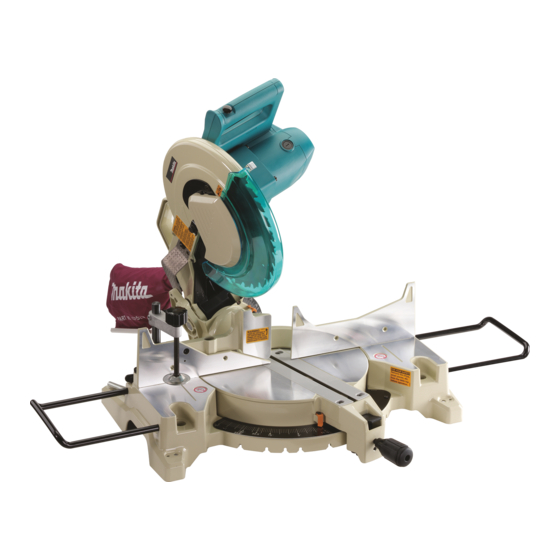
Compound miter saw equipped with electric blade brake 305 mm (12”)
Hide thumbs
Also See for LS1221:
- Instruction manual (65 pages) ,
- Parts breakdown (5 pages) ,
- Instruction manual (21 pages)
Table of Contents
Advertisement
Advertisement
Table of Contents

Related Manuals for Makita LS1221


Summary of Contents for Makita LS1221
- Page 1 Compound Miter Saw Equipped with Electric Blade Brake 305 mm (12”) MODEL LS1221 I N S T R U C T I O N WARNING: For your personal safety, READ and UNDERSTAND before using. SAVE THESE INSTRUCTIONS FOR FUTURE REFERENCE.
-
Page 2: Specifications
SPECIFICATIONS Blade diameter : ... 305 mm (12”) Hole diameter : ... 25.4 mm (1”) Max. Miter angle : ...Left 48°, Right 48° Max. Bevel angle : ...Left 45° Max. Cutting capacities (H x W) Bevel angle 0° 45° (left) No load speed (RPM) : ... - Page 3 5. DON’T USE IN DANGEROUS ENVIRON- MENT. Don’t use power tools in damp or wet locations, or expose them to rain. Keep work area well lighted. Don’t use tool in presence of flammable liquids or gases. 6. KEEP CHILDREN AWAY. should be kept safe distance from work area.
-
Page 4: Use Proper Extension Cord
Not More Than ADDITIONAL SAFETY RULES DO NOT let comfort or familiarity with product (gained from repeated use) replace strict adherence to miter saw safety rules. If you use this tool unsafely or incorrectly, you can suffer seri- ous personal injury. - Page 5 13. Make sure that the turn base is properly secured so it will not move during opera- tion. Use the holes in the base to fasten the saw to a stable work platform or bench. NEVER use tool where operator positioning would be awkward.
- Page 6 SAVE THESE INSTRUCTIONS WARNING: MISUSE or failure to follow the safety rules stated in this instruction manual may cause serious personal injury.
-
Page 7: Blade Guard
INSTALLATION 001794 1. Stopper pin 001827 1. Bolt FUNCTIONAL DESCRIPTION 001830 1. Blade guard Bench mounting When the tool is shipped, the handle is locked in the lowered position by the stopper pin. Release the stopper pin by lower- ing the handle slightly and pulling the stopper pin. This tool should be bolted with four bolts to a level and stable surface using the bolt holes provided in the tool’s base. -
Page 8: Positioning Kerf Board
Do not remove spring holding blade guard. If guard becomes discolored through age or UV light exposure, con- tact a Makita service center for a new guard. DO NOT DEFEAT OR REMOVE GUARD. Positioning kerf board This tool is provided with the kerf boards in the turn base to minimize tearing on the exit side of a cut. -
Page 9: Adjusting The Miter Angle
Maintaining maximum cutting capacity This tool is factory adjusted to provide the maximum cutting capacity for a 305 mm (12”) saw blade. When installing a new blade, always check the lower limit position of the blade and if necessary, adjust it as follows: First, unplug the tool. -
Page 10: Adjusting Bevel Angle
To adjust the bevel angle, loosen the lever at the rear of the tool counterclockwise. Push the handle to the left to tilt the saw blade until the pointer points to the desired angle on the bevel scale. Then tighten the lever clockwise firmly to secure the arm. -
Page 11: Electric Brake
NEVER use the tool if it runs when you simply pull the switch trigger without pressing the lock-off button. Return tool to a Makita service center for proper repairs BEFORE further usage. •... - Page 12 001829 1. Shaft lock 2. Socket wrench 001791 1. Hex bolt 2. Outer flange 3. Saw blade 4. Ring 5. Inner flange 6. Spindle Lock the handle in the raised position by pushing in the stop- per pin. To remove the blade, use the socket wrench to loosen the hex bolt holding the center cover by turning it counterclock- wise.
-
Page 13: Securing Workpiece
NOTE: If you connect a Makita vacuum cleaner to your saw, more efficient and cleaner operations can be performed. Securing workpiece WARNING: •... - Page 14 001549 1. Support 2. Turn base 001842 1. Sub-fence 001843 1. Sub-fence 001796 1. Vise arm 2. Vise rod 3. Guide fence 4. Holder 5. Holder assembly 6. Vise knob 7. Screw CAUTION: • When cutting long workpieces, use supports that are as high as the top surface level of the turn base.
- Page 15 001839 1. Vise plate 2. Vise nut 3. Vise knob 001809 1. Holder 2. Holder assembly Press the workpiece flat against the guide fence and the turn base. Position the workpiece at the desired cutting position and secure it firmly by tightening the vise knob. CAUTION: •...
-
Page 16: Operation
Gently press down the handle to perform the cut. If the handle is pressed down with force or if lateral force is applied, the blade will vibrate and leave a mark (saw mark) in the workpiece and the precision of the cut will be impaired. - Page 17 3. Bevel cut 001841 Loosen the lever and tilt the saw blade to set the bevel angle (Refer to the previously covered “Adjusting the bevel angle”). Be sure to retighten the lever firmly to secure the selected bevel angle safely. Secure the work- piece with a vise.
- Page 18 5. Cutting crown and cove moldings Crown and cove moldings can be cut on a compound miter saw with the moldings laid flat on the turn base. There are two common types of crown moldings and one type of cove moldings; 52/38° wall angle crown molding, 45°...
- Page 19 Lay crown molding with its broad back (hidden) surface down on the turn base with its CEILING CONTACT EDGE against the guide fence on the saw. • The finished piece to be used will always be on the LEFT side of the blade after the cut has...
- Page 20 30.3 32.5 29.9 32.2 29.4 31.8 29.0 31.5 28.6 31.1 28.2 30.8 27.7 30.4 27.3 Compound Miter Saw Miter and Bevel Angle Settings Wall Angle Bevel Angle Miter Angle (deg.) (deg.) (deg.) 30.1 26.9 29.7 26.5 29.4 26.1 29.0 25.7 28.7...
- Page 21 33.9 28.8 33.4 28.5 32.9 28.2 32.5 27.9 32.0 27.6 31.6 27.3 31.1 27.0 30.7 Compound Miter Saw Miter and Bevel Angle Settings Wall Angle Bevel Angle Miter Angle (deg.) (deg.) (deg.) 26.7 30.2 26.4 29.8 26.1 29.4 25.8 28.9 25.5...
- Page 22 4. Aluminum extrusion 5. Spacer block Crown molding stoppers (optional accessories) allow easier cuts of crown molding without tilting the saw blade. Install them on the base as shown in the figures. Position crown molding with its WALL CONTACT EDGE...
- Page 23 Over 10mm (3/8”) 1. Hole 001846 1. Set plate 2. Holder 3. Screw Over 580mm (22-3/4”) 105mm 115mm 115mm 105mm (4-1/8”) (4-1/2”) (4-1/2”) (4-1/8”) CAUTION: • Use straight wood of even thickness as the wood facing. • Use screws to attach the wood facing to the guide fence. The screws should be installed so that the screw heads are below the surface of the wood facing.
-
Page 24: Carrying Tool
001794 1. Stopper pin 001825 MAINTENANCE 001849 1. Hex bolt Carrying tool Make sure that the tool is unplugged. Secure the blade at 0° bevel angle and the turn base at right miter angle fully. Lower the handle fully and lock it in the lowered position by pushing in the stopper pin. - Page 25 3. 0° bevel angle adjusting bolt 001819 1. Triangular rule 2. Saw blade 3. Top surface of turn base Lower the handle fully and lock it in the lowered position by pushing in the stopper pin. Square the side of the blade with the face of the guide fence using a triangular rule, try-square, etc.
-
Page 26: Replacing Carbon Brushes
10 minutes. Then check the tool while running and electric brake operation when releasing the switch trigger. If electric brake is not working well, ask your local Makita service center for repair. -
Page 27: After Use
CAUTION: • These accessories or attachments are recommended for use with your Makita tool specified in this manual. The use of any other accessories or attachments might present a risk of injury to persons. Only use accessory or attachment for its stated purpose. - Page 28 Memo...
- Page 29 First-Class Postage Required Post Office will not deliver without proper postage. Makita U.S.A., Inc. 14930 Northam Street La Mirada, CA 90638-5753 Fold...
- Page 30 Paste 3. How did you learn about this product: Magazine From Dealer Newspaper Store Display Catalog 4. Most favored points are: Design Features Size Price Makita Brand MODEL NO. YEAR SERIAL NO. PHONE 20-29 30-39 40-49 Paste Paste Radio Exhibition...
-
Page 31: Factory Service Centers
Date Purchased When you need service: Send complete tool (prepaid) to one Dealer’s Name & Address of the Makita Factory Service Centers listed, or to an Authorized Makita Service Center. Be sure to attach a letter to the outside of Model No. -
Page 32: Warranty Policy
MAKITA LIMITED ONE YEAR WARRANTY Warranty Policy Every Makita tool is thoroughly inspected and tested before leaving the factory. It is warranted to be free of defects from workmanship and materials for the period of ONE YEAR from the date of original purchase.