Table of Contents
Advertisement
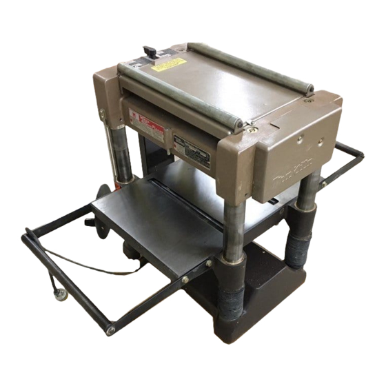
Planer
1 mm
11/32")
of
stock wtdth
over
304
mmll 1-314")
3 mm
1 1 1 8 " l
o f stock width
under
150 mm 15-718")
Max. srock
height
No
load
speed
12.7 mm
-
1 9 5 m m
6,500
,,,,
In,
1112"
-
7-518")
400
mm (15-3/4") MODEL
2040
2
9
m / m m
129
5
ftimin.1
396
mm
x
600
nim
115 5/8"
x
23
5/8"1
Overall dimenslons
(W
x
L
x
HI
570
mm
x
1,025
1 1 1 1 1 1
x
715
r n n l
Net weight
115
k g
(254
Ibsl
122 112"
x
40.318''
x
28 1 1 8 " l
INSTRUCTION MANUAL
SPEC IF
I
CAT
IONS
396 mm
I1 5~518")
Advertisement
Table of Contents

Related Manuals for Makita PLANER 2040


Summary of Contents for Makita PLANER 2040
- Page 1 INSTRUCTION MANUAL IONS SPEC IF 1 mm 11/32") mmll 1-314") 396 mm over 3 mm 1 1 1 8 " l I1 5~518") 150 mm 15-718") under Max. srock height 12.7 mm 1 9 5 m m 1112" 7-518") mm (15-3/4") MODEL stock wtdth m / m m o f stock width...
- Page 2 For Your Own Safety Read Instruction Manual Before Operating Planer GENERAL SAFETY PRECAUTIONS KNOW YOUR POWER TOOL. Read the owner's manual carefully. Learn the tools applications and limitations, as well as the specific potential hazards peculiar t o it. KEEP GUARDS IN PLACE and 3.
- Page 3 Ampere Rating More Than More Than 'Only the applicable parts of the Table need to be included. For instance. a 120-volt product need no include the 240-volt headina. 17. REDUCE THE RISK OF UNINTENTIONAL STARTING. Make sure switch in off position before plugging in. 18.
- Page 4 3LTAGE WARNING: Before connecting the tool t o a power source (receptacle, Itlet, etc.) be sure the voltage supplied is the same as that specified on the m e p l a t e of the tool. A power source with voltage greater than that specified )r the tool can result SERIOUS INJURY t o the user le tool.
- Page 5 Never stick your finger into damp wood. Turn off the planer and then clean out chips w i t h a stick. 18. Don't touch blades right after operation, they may be extremely hot and could burn your skin.
- Page 6 Do not try to than the specified amount in one pass. Make two passes rather than put an over- load on the planer that might cause trouble. Stock feed Align the stock to be cut with the top of the table.
- Page 7 Return Returning cut stock back to the front side is very easy if you use the convenient re- turn rollers on top. Stopper regulating depth Numerous workpieces can be planed to the same thickness very simply just by setting the stopper ring to the desired dimension. Do not crank the handle so hard that you force the stopper ring to move.
- Page 8 Loosen the pan hd. screws on the plates. Remove the chip guard, lift the lever and swing on the belt guard side to align the cutter drum Next, release the lever to make the drum stationary. Remove the 8 hex bolts with the socket wrench provided, then take cover (cutter retaining plate).
- Page 9 (i.e., prox. 5 - 6 mm (3/16” adjusting knife height on both knives, replace chip guard before. Replace guards after completing adjustments. Auto-planer guard (chip cover) should be secured original position. & the knife edge the position A t first, (see 5-6”...
-
Page 10: Adjusting Various Components
ows.) Loosen the pan head screw for each roller under the table. Use screwdriver to rotate the groove on the roller adjuster within 180 degrees on the four roller the figures for the correct range of adjustment of each roller adjuster. Rotat- ing the groove in the ascending direction causes the bed roller to rise;... - Page 11 the column. Adjusting infeed/outfeed rollers The infeed/outfeed rollers are factory adjusted. If the rollers require adjustment, please follow this procedure : Place straight and.lever piece of wood to raise the table and to bring the piece of wood into contact with the main frame. Then turn the crank handle half-turn counterclockwise to lower the table slightly.
- Page 12 MAINTENANCE CAUTION : Always be sure that the tool inspection or maintenance. Replacing carbon brushes 3emove and check the carbon brushes egularly. Replace when they wear down the limit mark. Keep the carbon brushes :lean and free to slip in the holders. Both arbon brushes should be replaced ame time.
- Page 13 The periodic lubrication should be per- formed with machine oil. (Oiling should be done with tool not operating.) To maintain product SAFETY and RELIABILITY, repairs, any other maintenance or adjustment should be performed by Makita Authorized or Factory Service Centers, always using Makita replacement parts.
- Page 14 ACCESSOR I ES C A U T I O N These accessories or attachments are recommended for use with your Makita tool specified in this manual The use of any other accessories or attachments might present a risk of injury to persons.
- Page 16 Jan -08-'96 MODEL 2040...
- Page 18 Spmg Lever 5 0 Bush 10 ComprFsIlO" sprmg 1 I Lock Pin Pan Heed Screw M 5 r 2 0 IWith Washer1 Bell cover Pan Head Screw M5x35 lWith Warhnrl Heed Sciew M 5 x I O IWOlh Washeil Bell covrr stay Scale Pan Head Screw M 5 r 1 4 IWith Washerl R l W f...
- Page 19 2040 MODEL DESCRlPTlDN MACHINE Hex Nul Spring Washer Flat Warher Herd Screw M6.18 IWllh Washer1 Trnrlon mate Max35 Square NeLk Bolt Motor Housing Rear Cover M5.12 Head Screw IWilh Warherl I n ~ ~ l a i i o n Washri Cdibon Brush Brush...
- Page 20 The tool has been abused, misused or improperly maintained: alterations have been made t o the 1001. IN NO EVFNT SHALL MAKITA BE LIABLE FOR ANY INDIRECT INCIDENTAL SEQUENTIAL DAMAGES FROM THE SALE APPLIES BOTH DURING AND AFTER THE TERM O F THIS WARRANTY.