
Related Manuals for Pyle PIPCAM5

Summary of Contents for Pyle PIPCAM5
- Page 1 Indoor Wireless/Wired P2P IP Network Camera PIPCAM5 www.pyleaudio.com Instruction Manual...
-
Page 2: Table Of Contents
CONTENTS 1. INTRODUCTION................................3 1.1 F .......................................3 EATURES 1.2 P ......................................3 ACKING 1.3 P ....................................4 RODUCT IEWS 1.4 PC S .................................. 6 YSTEM EQUIREMENTS 1.5 H ..................................6 ARDWARE NSTALLATION 1.6 S ..................................6 OFTWARE NSTALLATION 2. SOFTWARE OPERATION............................9 2.1 IP C .................................... -
Page 3: Introduction
6. OBTAINING TECHNICAL SUPPORT........................59 1. INTRODUCTION This is an integrated wireless IP Camera solution. It combines a high quality digital Video Camera with network connectivity and a powerful web server to bring clear pictures to your Desktop from anywhere on your local network or over the Internet. -
Page 4: Product Views
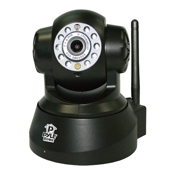
1.3 Product Views 1.3.1 Front View Figure 1.1 1 Light Sensitive Hole: For light sensitive photocell 2 Infrared LED: 10 LEDs 3 LENS: CMOS sensor with fixed focus lens. (Default is 6mm, 3.6mm optional) 4 Network Indicator LED: If there is network activity, the LED will blink 5 Microphone: Built-in microphone 6 Speaker: Built-in speaker 7 Wireless Antenna: WI-FI Antenna... -
Page 5: Rear Panel
1.3.2 Rear Panel Figure 1.2 LAN: RJ-45/10-100 base T Power: DC 5V/2A power supply Network Light: The green LED is on when connected to the network, the yellow LED blinks when data is transferred. Audio Output: The jack is used to connect an external speaker I/O PINS: 1: Output A 2: Output B 3: Alarm input 4: Input (GND) 1.3.3 Bottom View Figure 1.3... -
Page 6: Pc System Requirements
RESET BUTTON: Press and hold the RESET BUTTON for 30 Seconds to reset the camera back to the factory default settings. (Please keep the power on when doing a RESET) 1.4 PC System Requirements System configuration requirements: CPU: 2.06 GHZ or above. Memory: 256M or above. - Page 7 1. IP Camera Tool: Open the CD, double click “IPCamSetup.exe” then click next to complete the software installation. (Figure 1.6, 1.7, 1.8). 2. ActiveX: Double click “Appinstall.exe”—“Next”—“Install”—“Finish”. Figure 1.5 Figure 1.6 Figure 1.7...
- Page 8 Figure 1.8 After this is done, the icon “IP Camera Tool” will be displayed on your desktop . CAUTION: Before installing and using the product, please read the following precautions carefully and make sure they are fully understood. Use only the power adaptor included with the product. Use of an unauthorized power adapter may cause damage to your IP Camera.
-
Page 9: Software Operation
2. SOFTWARE OPERATION 2.1 IP Camera Tool When the Device has been mounted properly, you can double-click the Icon “IP Camera Tool” and a dialog box shown in Figure 1.9 will pop up . Figure 1.9 Note: The software searches IP Servers automatically over your LAN. There are 3 cases: 1. -
Page 10: Basic Properties
Figure 2.0 2.1.1 .1 Basic Properties There is some device information in the Basic Properties, such as Device ID, System Firmware Version, and Web UI Version.(Figure 2.1). The Device ID is the camera’s MAC ID, which should be the same as shown on the sticker on the bottom of the camera. - Page 11 Figure 2.2 Obtain IP from DHCP server: If clicked, the device will obtain IP from DHCP server. In other words, the camera will have a dynamic IP. (Make sure the Router which the camera connects to has DHCP function and DHCP is enabled).
-
Page 12: Upgrade Firmware
2.1.1.3 Upgrade Firmware Enter the correct User and Password to upgrade system Firmware and Web UI. Please upgrade system firmware first and then upgrade Web UI or it may damage the camera.(Figure 2.4). Figure 2.4 Please download the firmware package for the correct type of your camera before you upgrade. Follow the upgrade document carefully to upgrade. - Page 13 automatically and go to the camera login interface. (Figure 2.6). 2. To access the camera by IE Browser directly, just type the camera’s IP address, for example, if the camera’s IP address is 192.168.1.123: Figure 2.5 Figure 2.6 The default user name is admin, password is admin. Input the correct user name and password, the Sign In interface will pop-up.
-
Page 14: For Ie Browser
2.3 For IE Browser Choose ActiveX Mode (For IE Browser), and sign in Figure 2.8 Figure 2.9 The first time you login to the camera, you might get an ActiveX prompt as in the picture above, please click the prompt and choose Run Add-on, refresh and login to the camera again, then will see live video, as below. Figure 3.0... - Page 15 Note: If there is still no live video after you run ActiveX, and a red cross shows in the center of the screen, or even just a black screen, please try to enable the ActiveX options of IE security settings. Please do the following steps: 1.
-
Page 16: For Safari, Firefox, Google Browser
Figure 3.2 NOTE: Make sure that your firewall or anti-virus software doesn’t block the software or ActiveX. If you couldn’t see live video, please close your firewall or anti-virus software, and try again . 2.4 For Safari, Firefox, Google Browser Choose Server Push Mode (For Safari, Firefox, Google Browser), and sign in. -
Page 17: For Mobile Phone
2.5 For Mobile Phone Choose Sign in mobile phone, and sign in. Mobile phone doesn’t support ActiveX, so only some basic functions are available in this mode. It supports iPhone, Smart phone, 3G phone, etc. Normally, if the mobile phone supports network video, then it should work with your IP Camera. - Page 18 Figure 3.5 Channels: The IE software supports 9 channels. Click to get different windows. Click this one to view the main channel of the camera you login to. Click this one to view 4 Channels of cameras that are connected, from CH1 to CH4. Click this one to view 9 Channels of cameras that are connected, from CH1 to CH9.
-
Page 19: Osd Settings
OSD Settings: Figure 3.6 OSD: Means “On-Screen Display”, click “Audio video” > “OSD”, set display date and time on the video. Disabled: Clicking this one means clear the OSD. Color: Can set the OSD text color as black, yellow, red, white, blue etc. Add time stamp on record: if you click this, there will be time OSD on record video files. - Page 20 Figure 3.8 Figure 3.9 TOP Menu Figure 4.0 Click to get live video. When you want to get back to live video from other menus, just click it. Only under live video, you can do the operation on the right side, such as play, stop, snapshot etc. Click to get into play mode, when you click the stop icon, the video will be stopped, then if you click the play icon, it will show the video again.
-
Page 21: For Operator
2.8 For Operator When you login as Operator, you can enter the IP Camera for Operator. For operator, it not only supports all the functions for Visitor, but also supports these functions below: Figure 4.1 Audio Video Settings Figure 4.2 Audio buffer: Click this icon, it will show five numbers, which means 1/2/3/4/5 seconds buffer of audio. - Page 22 Figure 4.3 Mode: This mode is optional, 50HZ/60HZ for the users who use 50HZ/60HZ frequency, outdoor for users who want to use the camera to monitor towards an outdoor environment. NOTE: The camera should be used in an indoor environment (unless protected from the elements). Bright: Set the parameters to adjust the image quality of the video.
-
Page 23: For Administrator
Figure 4.5 Set Preset Position. It supports 15 preset positions. To control the camera’s rotation to a preset position, click Set Preset Position button it will pop-up a dialog frame (Figure 4.5), choose the number (1-15) you want to set it to. NOTE: if you set different positions with the same number, the camera will record the last position setting only. -
Page 24: Settings As Administrator
3. SETTINGS AS ADMINISTRATOR Administrator supports all the settings and operations of the camera. There are some special functions only for administrator as below: Figure 4.6 3.1 Multi-Device Settings Multi-Device Settings This camera can support max. 9 device channels at the same time. 3.1.1 Set Multi-Device in LAN In the Multi-Device Settings page, you can see all devices searched in LAN. - Page 25 Figure 4.7 Click Live Video and then select to see four channels, or click to see nine channels. Figure 4.8...
- Page 26 Figure 4.9 3.1.2 Set Multi-Device for WAN If you want to view cameras from the internet, you have to add these devices by DDNS domain name. Make sure all these cameras you want to add have DDNS set successfully. (See 3.7 DDNS Service Settings) Login to the first camera by DDNS domain name and port, this camera will be as the host camera.
- Page 27 DDNS domain name, just set different port number for each different camera. Figure 5.1 Note: Add the other camera in the same way, Click submit to add all of them. Figure 5.2 Click Live Video and then selec t to see four channels, or to see nine channels.
-
Page 28: Upgrade Device Firmware
In this case, you can see all the cameras from a remote position by internet, for example, if you are on a business trip, you can use the first camera’s (Host camera) DDNS to view all the devices via the internet. Figure 5.3 3.1.3 Upgrade Device Firmware If you want to upgrade the camera, please upgrade Device Firmware first, then upgrade Web UI. -
Page 29: Network Settings
Click Restore Factory Settings, will pop-up a prompt, select OK, all the parameter will be returned to factory settings, and the device will reboot. Figure 5.5 3.1.5 Reboot Device Click Reboot the device, will pop-up a prompt, select OK, then the device will reboot Figure 5.6 3.2 Network Settings Click Network, will pop-up the prompt as below:... - Page 30 Figure 5.7 If you don’t know the Subnet Mask, Gateway, DNS Server. Please check the Local Area Connection Status of your computer; it contains all this information, steps as below: 1. Control PanelNetwork ConnectionsLocal Area Connections Support Details 2.
-
Page 31: Wireless Lan Settings
If the router supports DHCP function, you can choose “Obtain IP from DHCP Server” to get dynamic IP. Figure 6.0 Http Port: In most cases, you can leave this value as-is. However, if your Internet Service Provider blocks this port, you may change it to another port number such as 8060. 3.4 Wireless LAN Settings ... - Page 32 Figure 6.2 Figure 6.3 Figure 6.4...
-
Page 33: Adsl Settings
Figure 6.5 3.5 ADSL Settings When connected to the Internet through ADSL directly, you can enter the ADSL username And password obtained from ISP. Figure 6.6 Figure 6.7 3.6 UPnP Settings Click UPnP Settings to choose Using UPnP to Map Port: ... -
Page 34: Ddns Service Settings
Select it and click Submit, then the camera will support UPnP port forwarding automatically. It’s helpful for using DDNS. If your router supports UPnP, then you won’t need do port forwarding in the router . Figure 6.9 NOTE: Here UPnP is only for port forwarding. It relates to the security settings of your router, make sure the UPnP function of your router is ON. - Page 35 Third Party DDNS If you use third party DDNS, please choose the server you use, such as “3322.org” or “dyndns.org” as below: Figure 7.2 Figure 7.3 You have to register an account first, enter the user, password, and host. NOTE: Only one DDNS can be chosen, for example, if you use the manufacturer’s DDNS, the third party one won’t work, if you use the third party DDNS, the manufacturer’s one won’t work.
- Page 36 Figure 7.4 Make sure the “Subnet Mask”, “Gateway”, “DNS Server” is the same as your router. Set Port Forwarding in the router. This is the most important step. You need to set port forwarding in your router, to refer to the IP of your camera correctly, for DDNS to work.
- Page 37 1. Login to the router. 2. Choose “Firewall”, select “Virtual Servers” 3. Input the port (don’t use 80) and IP address, then click save. NOTE: The port and IP address should be the same as the camera. Figure 7.6 DLINK: 1.
-
Page 38: P2P Settings
Step: “Login”>”System”>”Device Info” Figure 7.8 Figure 7.9 3.8 P2P settings Check P2P information here, using the GUID, you can view the camera via iPhone, or Android phone at any time, from anywhere, when connected to the network. You can set your own user name and password here. -
Page 39: System Settings
3.9 System Settings Figure 8.0 3.9.1 Device Info You can find the information about Device ID, Firmware Version, Embedded Web UI Version, Alias, Alarm Status, DDNS Status, UPnP Status and MSN status. Figure 8.1 3.10 Alias Settings Default device name is anonymous. You set any new name for your camera here, then click Submit . -
Page 40: Date &Time Settings
Figure 8.2 3.11 Date &Time Settings Set the date and time for your camera. Choose the Clock Time zone of your country. You can choose Sync with NTP Server (Figure 8.3) or Sync with PC Time (Figure 8.4). Figure 8.3 Figure 8.4 3.12 Users Settings Eight accounts are acceptable for this system. -
Page 41: Pan, Tilt, (Ptz) Settings (Note, There Is No Zoom Feature On This Model)
Figure 8.5 3.13 Pan, Tilt, (PTZ) Settings (note, there is no Zoom feature on this model) Figure 8.6 1. Go center on boot: The camera rotates to the center automatically when it starts. 2. PT speed: Set Pan/Tilt speed. 3. Upward patrol speed: Set the speed of cruising upward. 4. -
Page 42: Backup & Restore
Figure 8.7 Set the pilot lamp mode, to one of the following three options: (1) Non-connected network out: Blinks while connected to the internet and turn off when disconnected. (2) Non-connected network with more slow-frequency flicker: Blinks while connect to the internet and more slower when disconnected. -
Page 43: Other Settings
NOTE: Set the port forwarding successfully before setting MSN (Refer to port forwarding in DDNS settings). Then go to the MSN settings page, fill in the correct user name and password, add the MSN buddy, max. up to 10 friends, after submitting, the user(s) will be shown in your MSN friend list. Click System—Device Info to check the MSN status. -
Page 44: Mail Service Settings
3.17 Mail Service Settings Set Mail Service Settings to enable the camera to send e-mail alerts when motion is detected. Figure 9.1 Sender: Make sure the sender mailbox server provider supports SMTP, and the mailbox should not enable SSL or TSL encryption. Receiver: Here you can set four receivers. -
Page 45: Ftp Service Settings
and try again. 1) Cannot connect to the server. 2) Network Error. Please try later. 3) Server Error. 4) Incorrect user or password. 5) The sender is denied by the server. Maybe the server needs to authenticate the user, please check and try again. - Page 46 Figure 9.4 FTP Server: If your FTP server is set up in LAN. You can set as Figure 9.3. If you have an FTP server that can be accessed from the Internet, you can set as Figure 9.4. FTP Port: Usually the port is 21. FTP Upload Folder: Make sure that the folder you plan to store images in exists.
-
Page 47: Alarm Service Settings
Figure 9.6 Enter Alarm Service Settings page to configure Motion Detection function. 3.19.1 Motion Detect Armed If you enable Motion Detect Armed, it will record and make an alarm sound when there is motion detected. Figure 9.7 After you enable motion detect armed, if there is motion detected, the Alarm Status will turn to Motion Detect Alarm. - Page 48 You can choose level 1-10; level 10 means the most sensitive, 1 means the least sensitive. Figure 9.9 3.19.3 Alarm Input Armed / IO Linkage on Alarm If you want to connect external alarm devices, when it’s an alarm input device, choose Alarm Input Armed to enable it, when it’s an output device, choose IO Linkage on Alarm to enable it.
- Page 49 There are two options for Output Level. (Figure 10.2). High: When chosen, the IO Pins work as a switch that is closed. Low: When chosen, the IO Pins work as a switch that is switching off Figure 10.2 3.19.4 IO Pins for IO Alarm Linkage Figure 10.3 I/O PINS: 1 Output 2 Output 3 Alarm input 4 Input (GND) Input pins: The input pins can be used for 1-way external sensor input.
-
Page 50: Send E - Mail On Alarm
Figure 10.4 Scheduler Here you can set the camera alarm during the time you set. Choose Scheduler and set the date & time range. (Figure 10.5) From Monday to Sunday, and every day divided into 24 hours, each hour divided into 4 quarters. Left click the frame of the time range, it will turn to blue color, which means the time you choose to be armed. -
Page 51: Path Settings
6. If you set Upload Image on Alarm, it will upload images to the FTP Server you set already, once alarmed. (Figure 10.4). NOTE: Each alarm only lasts for approx one minute, all the above functions for motion detection triggered only. -
Page 52: Server Push Mode (For Safari, Firefox, And Google Browser)
Figure 11.1 3.22 Server Push Mode (For Safari, FireFox, and Google Browser) Choose Server Push Mode, login the camera, you will see the main user interface as below: Figure 11.2 NOTE: Server Push Mode does not support ActiveX. Play, Stop, Record, Audio, Talk, Multi-device settings, Path settings functions are controlled by ActiveX, so if you use Safari, Firefox, Google chrome browser, it is not possible to use these options. -
Page 53: Sign In Mobile Phone
3.23 Sign in mobile phone If you are using a mobile phone, choose Sign in mobile phone, login to the camera, you will see the main user interface as below: Figure 11.3 NOTE: Mobile phone Mode doesn’t support ActiveX. In mobile phone mode, it only supports some simple functions, such as Resolution, Mode, Bright, Contrast, Pan/Tilt control, Snapshot, Reversal, Mirror, IO Linkage functions. -
Page 54: Appendix
4. APPENDIX 4.1 Frequently Asked Questions Note: For most problems you might encounter, please check Network connections first. Check the working status revealed by the indicators on the network server, hub, exchange and network card. If abnormal, check the network connections. 4.1.1 I have forgotten the administrator username and/or password. - Page 55 Some typical reasons: 1. ActiveX controller is not installed correctly (for more details see: Figure 2.9 - Figure 3.1). 2. The port that the camera is using is blocked by your Firewall or Anti-virus software. Please change to another port number and try again. (Figure 3.2). 3.
-
Page 56: Problems With Network Bandwidth
Don’t enable MAC address filter. 4.1.11 I can’t see other cameras in multi-device configuration by remote access If you want to view all the cameras in your WAN. Make sure that each camera you add in multi-device settings can be logged-in using DDNS name and port number. Use DDNS domain name to fill in the host checkbox, not camera’s LAN IP. -
Page 57: Specifications
Username and password Default administrator username: admin Default administrator password: admin. 5. SPECIFICATIONS Model PIPCam 5 Image Sensor Sensor 1/5” Color CMOS Sensor Resolution 640 x 480 Pixels (300k Pixels) IR Lens F 2.0 6mm/ 3.6mm 90° Diagonally, 68° Horizontally Viewing Angle Minimum Illumination 0.5Lux @ F2.0... -
Page 58: Specifications
PC System Requirement 2.0 GHZ or above Memory Size 256 MB or above Display Card 64M or above memory Supported OS Microsoft Windows 98/ME/2000/XP/Vista/7 Browser IE6.0, IE7.0, IE8.0, Firefox, Safari, Google chrome etc Certification CE, FCC, RoHS Warranty 90 Day Limited Warranty 6.