Advertisement
Table of Contents
- 1 Table of Contents
- 2 Before You Begin
- 3 Important Safety Notices
- 4 Warning Label Placement
- 5 Smith Machine Hardware Pack
- 6 Smith Machine Assembly Instructions
- 7 Smith Machine Parts List
- 8 Multi-Purpose Bench Hardware Pack
- 9 Multi-Purpose Bench Assembly Instructions
- 10 Bench Exploded Diagram
- 11 Multi-Purpose Bench Parts List
- 12 Weight Resistance Chart
- 13 Limited Warranty
- 14 Ordering Parts
- Download this manual
NOTE:
Please read all instructions
carefully before using this
product
Table of Contents
Safety Notice
Hardware Pack
Assembly Instruction
Parts List
Warranty
Ordering Parts
Model
SM-4008
Retain This
Manual for
Reference
100806
OWNER'S
MANUAL
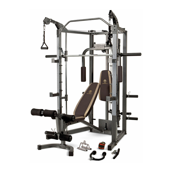
SMITH MACHINE
14777 DON JULIAN RD., CITY OF INDUSTRY, CA 91746
Tel: (800) 999-8899 Fax: (626) 961-9966
www.impex-fitness.com
info@impex-fitness.com
MARCY
SM-4008
®
IMPEX
INC.
®
Advertisement
Table of Contents

Related Manuals for Impex MARCY SM-4008


Summary of Contents for Impex MARCY SM-4008
- Page 1 Hardware Pack SM-4008 Assembly Instruction Parts List Warranty Ordering Parts Model SM-4008 Retain This Manual for Reference 100806 OWNER'S MANUAL ® IMPEX INC. 14777 DON JULIAN RD., CITY OF INDUSTRY, CA 91746 Tel: (800) 999-8899 Fax: (626) 961-9966 www.impex-fitness.com info@impex-fitness.com...
-
Page 2: Table Of Contents
BEFORE YOU BEGIN ® ® Thank you for selecting the MARCY SM-4008 by IMPEX INC. For your safety and benefit, read this manual carefully before using the machine. As a manufacturer, we are committed to provide you complete customer satisfaction. -
Page 3: Important Safety Notices
THIS IS ESPECIALLY IMPORTANT FOR INDIVIDUALS OVER THE AGE OF 35 OR PERSONS WITH PRE-EXISTING HEALTH PROBLEMS. READ ALL INSTRUCTIONS BEFORE USING ANY FITNESS EQUIPMENT. IMPEX INC. ASSUMES NO RESPONSIBILITY FOR PERSONAL INJURY OR PROPERTY DAMAGE SUSTAINED BY OR THROUGH THE USE OF THIS PRODUCT. -
Page 4: Warning Label Placement
WARNING LABEL PLACEMENT The warning labels shown here have been placed on the Rear Base, and Bench Rear Stabilizer. If the labels are missing or illegible, please call customer service at 1-800-888-8899 for replacements. Apply the labels in the location shown. -
Page 5: Smith Machine Hardware Pack
SMITH MACHINE HARDWARE PACK NOTE: The following parts are not drawn to scale. Please use your own ruler to measure the size. - Page 6 SMITH MACHINE HARDWARE PACK NOTE: The following parts are not drawn to scale. Please use your own ruler to measure the size.
- Page 7 SMITH MACHINE HARDWARE PACK NOTE: The following parts are not drawn to scale. Please use your own ruler to measure the size.
- Page 8 SMITH MACHINE HARDWARE PACK...
-
Page 9: Smith Machine Assembly Instructions
SMITH MACHINE ASSEMBLY INSTRUCTION Tools Required Assembling the Machine: Two Adjustable Wrenches and Allen Wrenches. NOTE: It is strongly recommended that two or more people assemble this machine to avoid possible injury. STEP 1 (See Diagram 1) A.) Do not tighten Nuts and Bolts until instructed to do so. B.) Insert a Base Frame (#5) into the Rear Left Vertical Frame (#3). - Page 10 STEP 2 (See Diagram 2) A.) Do not tighten the Nuts and Bolts until instructed to do so. B.) Insert a Guide Rod (#24) into the hole on left Base Frame (#5). Secure it with one M8 x 2 3/8” Allen Bolt (#103), two Ø 5/8” Washers (#106), and one M8 Aircraft Nut (#109). Slide the Left Lower Safety Stop Frame (#26) onto the Guide Rod, and then slide one Safety Stop Frame (#25) onto the Guide Rod.
- Page 11 DIAGRAM 2...
- Page 12 STEP 3 (See Diagram 3) A.) Do not tighten all Nuts and Bolts until instructed to so. B.) Attach the Middle Vertical Frame (#9) under the Rear Top Beam (#6) and onto the Rear Base Frame (#8). C.) Attach the Lower Pulley Frame (#16) to the Middle Vertical Frame from rear. Attach the Foot Plate (#32) to the Middle Vertical Frame from front.
- Page 13 DIAGRAM 3...
- Page 14 STEP 4 (See Diagram 4) A.) Attach the Butterfly Base (#11) to the front of Middle Vertical Frame (#9). Attach the Butterfly Pulley Bracket (#14) to the Middle Vertical Frame. Secure them together with two M10 x 2 ½” Carriage Bolts (#88), two Ø ¾” Washers (#107), and two M10 Aircraft Nuts (#110).
- Page 15 STEP 5 (See Diagram 5) A.) Insert the pivot on the Right Butterfly (#13) into the hole on the Butterfly Base from bottom. Secure it with one Lock Ring (#35), one Ø ¾” Washer (#107), and one M10 x 5/8” Allen Bolt (#87).
-
Page 16: Cable Loop Diagram
CABLE LOOP DIAGRAM... - Page 17 STEP 6 (See Diagram 6 & Cable Loop Diagram) A.) Attach one end of 113” Butterfly Cable (#45) to the clip on Left Butterfly (#12). Draw the Cable to the left Swivel Pulley Bracket (#15). B.) Attach a Pulley (#62) and two Cable Retainers (#78) to the Bracket. C.) Secure them with one M10 x 2”...
- Page 18 STEP 7 (See Diagram 7-1, 7-2 & Upper Cable Loop Diagram) A.) Attach the two Cross-over Swivel Pulley Brackets (#10) to left and right Upper Side Frame (#7). Secure each Bracket with four M8 x 3/8” Allen Bolts (#101) and four Ø 5/8” Washers (#106).
- Page 19 DIAGRAM 7-1...
- Page 20 DIAGRAM 7-2...
- Page 21 UPPER CABLE (#47) LOOP DIAGRAM...
- Page 22 STEP 8 (See Diagram 8 & Cable Loop Diagram) A.) Attach one end of the 97” Sliding Weight Post Cable (#46) to the Rear Upper Frame (#18). Secure it with one M10 x 2 3/8” Allen Bolt (#118), two Ø ¾” Washers (#107), and one M10 Aircraft Nut (#110).
- Page 23 DIAGRAM 8...
- Page 24 STEP 9 (See Diagram 9) A.) Draw the 152” Lower Cable (#44) through the opening on Foot Plate (#32) to the opening on bottom of Middle Vertical Frame (#9). B.) Attach a Pulley (#62) to the opening. Secure it with one M10 x 2 ½” Allen Bolt (#95), two Ø 1”...
- Page 25 DIAGRAM 9...
- Page 26 STEP 10 (See Diagram 10) A.) NOTE: Help of another person is strongly recommended for this step. Place the Lifting Sleeve (#28) in between the two Safety Stop Frames (#25). Align the holes. Insert the Weight Bar (#29) into the Safety Stop Frame from one end and through the Lifting Sleeve to the other Safety Stop Frame on the opposite side.
-
Page 28: Smith Machine Parts List
SMITH MACHINE PARTS LIST KEY NO. DESCRIPTION Q’ty Front Left Vertical Frame 1 ½” Square End Cap Front Right Vertical Frame Pulley Rear Left Vertical Frame Small Pulley Rear Right Vertical Frame Butterfly Arm Foam Roll Base Frame 1 ¾” Square End Cap Rear Top Beam Left Safety Rubber Bumper Upper Side Frame... -
Page 29: Multi-Purpose Bench Hardware Pack
MULTI-PURPOSE BENCH HARDWARE PACK NOTE: The following parts are not drawn to scale. Please use your own ruler to measure the size. - Page 30 MULTI-PURPOSE BENCH HARDWARE PACK NOTE: The following parts are not drawn to scale. Please use your own ruler to measure the size.
-
Page 31: Multi-Purpose Bench Assembly Instructions
MULTI-PURPOSE BENCH ASSEMBLY INSTRUCTION Tools Required for Assembling the Machine: Two Adjustable Wrenches and Allen Wrenches. NOTE: It is strongly recommended that this machine be assembled by two or more people to avoid possible injury. STEP 1 (See Diagram 1) A.) Do not tighten Nuts and Bolts until instructed to do so. - Page 32 STEP 2 (See Diagram 2) A.) Attach the Incline Support (#8) to the middle side holes on the two Backrest Supports (#7). Secure it with one M10 x 6 7/8” Allen Bolt (#26), two Ø ¾” Washers (#35), and one M10 Aircraft Nut (#37). Do not tighten the Nut and Bolt yet.
- Page 33 STEP 3 (See Diagram 3) A.) Place the Backrest Board (#11) onto the Backrest Supports (#7). Secure it with four M8 x 1 5/8” Allen Bolts (#32) and 5/8” Washers (#36). B.) Place the Seat Pad (#10) onto the two Seat Brackets (#4). Secure it with four M8 x 1 1/8”...
- Page 34 STEP 4 (See Diagram 4) A.) Attach the Leg Developer (#5) to the open bracket on the Front Post (#2). Secure it with one M10 x 3” Allen Bolt (#29), two ¾” Washers (#35), and one M10 Aircraft Nut (#37). B.) Insert the Leg Developer Weight Post (#6) into the hole on Leg Developer.
-
Page 36: Multi-Purpose Bench Parts List
MULTI-PURPOSE BENCH PARTS LIST KEY NO. DESCRIPTION Q’ty Main Frame Front Post Rear Stabilizer Seat Bracket Leg Developer Leg Developer Weight Post Backrest Support Incline Support Front Stabilizer Seat Pad Backrest Board 5/8” x 1 1/8” End Cap Foam Tube Foam Roll Olympic Sleeve Foam Roll End Cap... -
Page 37: Weight Resistance Chart
SM-4008 WEIGHT RESISTANCE CHART Station Ratio Example Low Pulley 100% 10 lb. plate creates 10 lb. resistance Butterfly (both arms) 100% 10 lb. plate creates 5 lb. resistance Left Cross-Over 10 lb. plate creates 5 lb resistance Right Cross-Over 10 lb. plate creates 5 lb resistance *Numbers are approximate. -
Page 38: Limited Warranty
IMPEX. IMPEX is not responsible or liable for indirect, special or consequential damages arising out of or in connection with the use or performance of the product or other damages with respect to any economic loss, loss of property, loss of revenues or profits, loss of enjoyments or use, costs of removal, installation or other consequential damages or whatsoever natures.