Table of Contents
Advertisement
Quick Links
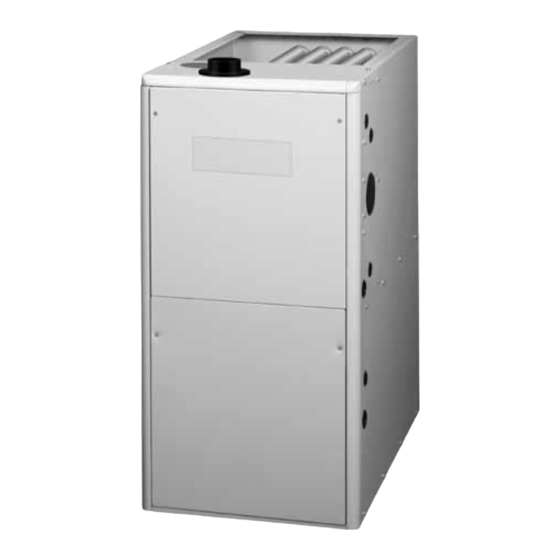
Single Stage Condensing Gas Furnaces
INSTALLATION INSTRUCTIONS
*SC Upflow / Horizontal
Model
WARNING:
FIRE OR EXPLOSION HAZARD
• Failure to follow safety warnings exactly could
result in serious injury or property damage.
• Installation and service must be performed
by a qualified installer, service agency or the
gas supplier.
• Do not store or use gasoline or other
flammable vapors and liquids in the vicinity
of this or any other appliance.
WHAT TO DO IF YOU SMELL GAS
• Do not try to light any appliance.
• Do not touch any electrical switch; do not
use any phone in your building.
• Leave the building immediately.
• Immediately call your gas supplier from a
neighbor's phone. Follow the gas supplier's
instructions.
• If you cannot reach your gas supplier, call
the fire department.
DO NOT DESTROY THIS MANUAL. KEEP IN A SAFE PLACE FOR FUTURE REFERENCE.
*SD Upflow / Horizontal
Models
RISQUE D'INCENDIE OU D' EXPLOSION
• Le non-respect des avertissements de
sécurité pourrait entraîner des blessures
graves, la mort ou des dommages matériels.
• L'installation et l'entretien doivent être
effectués par un installateur qualifié, un
organisme de service ou le fournisseur de
gazstaller, service agency or the gas supplier.
• Ne pas entreposer ni utiliser de l'essence ni
d'autres vapeurs ou liquides inflammables
dans le voisinage de cet appareil, ni de tout
autre appareil.
QUE FAIRE S'IL Y A UNE ODEUR DE GAZ
• Ne pas tenter d'allumer aucun appareil.
• Ne toucher à aucun interrupteur électrique;
n'utiliser aucun téléphone dans le bâtiment.
• Évacuer l'immeuble immédiatement.
• Appeler immédiatement le fournisseur de
gaz en employant le téléphone d'un voisin.
Respecter à la lettre les instructions du
fournisseur de gaz.
• Si personne ne répond, appeler le service des
incendies.
92.1% & 95.0% AFUE
*SL & *SM Downflow
AVERTISSEMENT
Models
Advertisement
Table of Contents

Related Manuals for Nordyne SC


Summary of Contents for Nordyne SC
- Page 1 Single Stage Condensing Gas Furnaces 92.1% & 95.0% AFUE INSTALLATION INSTRUCTIONS *SL & *SM Downflow *SC Upflow / Horizontal Models Model *SD Upflow / Horizontal Models WARNING: AVERTISSEMENT RISQUE D’INCENDIE OU D’ EXPLOSION FIRE OR EXPLOSION HAZARD • Le non-respect des avertissements de •...
-
Page 2: Table Of Contents
TABLE OF CONTENTS Inducer & Venting Options ........18 IMPORTANT SAFETY INFORMATION ..... 3 Inducer Assembly Rotation ........18 CODES & REQUIREMENTS ........4 Pressure Switch Tubing ........18 Combustion Air Quality..........5 Alternate Pressure Switch Location ..... 18 Heating Load ............5 Accessories ............. -
Page 3: Important Safety Information
Figure 31. *SL & *SM Cabinet Dimensions ..33 INSTALLER: Please read all instructions before servicing Figure 32. *SC & *SD Cabinet Dimensions ..34 this equipment. Pay attention to all safety warnings and any other special notes highlighted in the manual. Safety Airflow Data ............. -
Page 4: Codes & Requirements
• To minimize equipment failure or personal injury, it is • This furnace is designed to operate with a maximum essential that only qualified individuals install, service, or external pressure rise of 0.5 inches of water column. maintain this equipment. If you do not posses mechanical Consult Table Table... -
Page 5: Combustion Air Quality
Combustion Air Quality 2. For direct-vent appliances, mechanical-vent heating appliances or domestic hot water equipment where the CAUTION: bottom of the vent terminal and the air intake is installed above four feet above grade the following requirements must be satisfied: Combustion air must not be drawn from a a.) A (CO) detector and alarm shall be placed on each corrosive atmosphere. -
Page 6: Operation Of Furnace During Construction
Installation in a Garage Operation of Furnace During Construction WARNING: CAUTION: Do not place combustible material on or against Failure to follow these instructions will void the the furnace cabinet or within 6 inches of the factory warranty and may significantly reduce vent pipe. -
Page 7: Combustion Air & Venting Requirements
COMBUSTION AIR & VENTING REQUIREMENTS WARNING: AVERTISSEMENT: RISQUE D’EMPOISONNEMENT AU CARBON MONOXIDE POISONING HAZARD MONOXYDE DE CARBONED Failure to follow the steps outlined below for each appliance connected to the venting Le non-respect des consignes suivantes portant system being placed into operation could sur chacun des appareils raccordés au système result in carbon monoxide poisoning or death. -
Page 8: Direct Vent Furnaces
Important Information Another important consideration when selecting one or • This furnace must be vented in compliance with two pipe installation is the quality of the Indoor air which can sometimes be contaminated with various household the current revision of the National Fuel Gas Code chemicals . -
Page 9: Air From Inside
by the total input rate of all appliances in the space. In all cases, the minimum dimension of any combustion air Vent or Chimney opening is 3 inches. Ventilation Louvers Air From Inside (each end of attic) If combustion air is taken from the heated space, the two Outlet openings must each have a free area of at least one square NOTE: Air openings shall... -
Page 10: Alternate Method Of Providing Air From Outside
Alternate Method of Providing Air from Outside If acceptable under local Codes, it is permitted to provide Vent or outside air using one opening (See NFGC). Generally, Chimney confined spaces must have two openings in the space for combustion air. One opening must be within 12 inches of Air Duct Water Air Ducts must be... -
Page 11: Vent Pipe Material
Category IV appliances operate with positive vent pressure Vent Pipe Length & Diameter and therefore require vent systems which are thoroughly In order for the furnace to operate properly, the combustion sealed. They also produce liquid condensate, which is air and vent piping must not be excessively restrictive. slightly acidic and can cause severe corrosion of ordinary •... -
Page 12: Vent Pipe Installation
Vent Pipe Installation Outdoor Terminations - Horizontal Venting • Vent and combustion air intake terminations shall be installed as shown in Figure 7 & Figure 8 and in CAUTION: accordance with these instructions: • Vent termination clearances must be consistent with the Combustion air must not be drawn from a NFGC, ANSI 2223.1/NFPA 54 and/or the CSA B149.1, corrosive atmosphere. -
Page 13: Outdoor Terminations - Vertical Venting
• For optimal performance, vent the furnace through a Outdoor Terminations - Vertical Venting wall that experiences the least exposure to winter winds. Termination spacing requirements from the roof and from • The vent termination shall be located at least 3 ft. each other are shown in Figure 10. -
Page 14: Existing Installations
CIRCULATING AIR REQUIREMENTS Maximum Flue Pipe Length (FEET) Winter Design in Unconditioned & Exterior Spaces WARNING: Temperature Without Insulation With Insulation* Do not allow combustion products to enter the circulating air supply. Failure to prevent the circulation of combustion products into the living space can create potentially hazardous *NOTE: Insulation thickness greater than 3/8 inch, based on an R value of 3.5 (ft x F x hr) / (BTU x in.) -
Page 15: Return Air Connections
and outdoor air is used, the ducts and damper system 4 knockouts to expose the blower assembly. Position the return air duct over the opening and secure to the must be designed so that the return air supply to the side with sheet metal screws. -
Page 16: Furnace Installation
12 inches past the top and front of the furnace. *SC & *SD series gas furnaces offer a wide range of installation options, including installation in the upflow or If suspending the furnace from the ceiling, assemble a... -
Page 17: Downflow Furnaces
WARNING: Failure to install the downflow sub-base kit may result in fire,property damage or personal injury. To install an *SL & *SM series gas furnace on combustible flooring, a special sub-base is required. Downflow sub- base kits are factory supplied accessories and are listed according to the cabinet letter of the furnace. -
Page 18: Inducer & Venting Options
Figure 16 (page 19) display the proper routing of pressure Right Option 21 Option 29 switch tubing for *SC & *SD furnaces. Downflow (*SL & Option 25 Option 26 Option 30 *SM) furnaces require only one switch connected to the... - Page 19 Figure 15. Pressure Switch Tubing for *SD038 Furnaces Only Figure 16. Pressure Switch Tubing for Upflow Furnaces (Models *SC054, *SC072, *SC090, *SC108, & *SC120) (Models *SD054, *SD072, *SD090, *SD108, & *SD120) Figure 17. Pressure Switch Tubing for Downflow Furnaces (Models *SL054, *SL072, *SL090, & *SL120) (Models *SM054, *SM072, *SM090, &...
-
Page 20: Accessories
1. Shut off any electrical power to the furnace. 2. Label and disconnect the tubing and wires from the pressure switch (Figure 18). 3. Remove two screws securing the pressure switch to the inducer housing. 4. Remove the pressure switch from the mounts on the inducer housing and relocate it to the other set of mounts FRONT 90°... -
Page 21: Pvc Components
See Figure alignment with other vent pipes. 21. NOTE: If supplied with your furnace, the NORDYNE PVC trap (664659) may be used in place of the reducer Alternate Orientation and 1/2” X 1/2” hose barb 1. -
Page 22: Bottom Panel Removal
4. Carefully pull the blower assembly (4) out thru the front of the furnace. 2” x 3” PVC Coupling 5. Remove all screws (5) securing bottom panel (6) to bottom of furnace and front brace (7). 6. Lift up and slide bottom panel (6) out through front of Coil Box furnace. -
Page 23: Gas Supply & Piping
GAS SUPPLY & PIPING • All gas piping must be installed in compliance with WARNING: local codes and utility regulations. In the absence of local codes the gas line installation must comply FIRE OR EXPLOSION HAZARD with the latest edition of the National Fuel Gas Code •... -
Page 24: High Altitude Application (Natural Gas Only)
For example, the input needs to be reduced 8% at 2,000 AVERTISSEMENT: feet, 12% at 3,000 feet, etc. This deration is in reference to the input rate and gas heating value at sea level. RISQUE D’INDENDIE OU D’EXPLOSION To derate the furnace requires knowing the heating value of the gas at the installation site. - Page 25 *SC SERIES Note “A” Note “A” Note “B” Note “B” Right Side Entry Left Side Entry *SD SERIES Note “A” Note “A” Note “B” Note “B” Left Side Entry Right Side Entry (1) Automatic Gas Valve (2) Burner Assembly (3) Dripleg...
- Page 26 *SL SERIES Note “A” Note “A” Note “B” Note “B” Right Side Entry Left Side Entry *SM SERIES Note “A” Note “A” Note “B” Note “B” Right Side Entry Left Side Entry (1) Automatic Gas Valve (2) Burner Assembly (3) Dripleg (w/ manual shut-off) (4) Elbow (5) Ground Joint Union...
-
Page 27: Converting From Natural Gas To Lp / Propane
ELECTRICAL WIRING Converting from Natural Gas to LP / Propane WARNING: WARNING: The furnace was shipped from the factory ELECTRICAL SHOCK,FIRE OR EXPLOSION equipped to operate on natural gas.Conversion HAZARD to LP / Propane gas must be performed by Failure to follow safety warnings exactly could qualified service personnel using a factory result in serious injury or property damage. -
Page 28: Line Voltage Wiring
Line Voltage Wiring to the black wire.The furnace will not operate unless the polarity and ground are properly connected as It is recommended that the line voltage (115 VAC) to shown in Figure the furnace be supplied from a dedicated branch circuit containing the correct fuse or circuit breaker for the furnace Grounding as listed in... -
Page 29: Thermostat / Low Voltage Connections
Thermostat / Low Voltage Connections Twinning • The furnace is designed to be controlled by a 24 VAC Single stage furnaces are not supplied with a built- in twinning capability. Other valuable features and thermostat. The thermostat’s wiring must comply with enhancements were made to the new control that made it the current provisions of the NEC (ANSI/NFPA 70) and necessary to remove the twinning capability. -
Page 30: Start-Up & Adjustments
must not exceed the rate shown on the furnace rating plate. THERMOSTAT At altitudes above 2,000 feet, it must not exceed that on FURNACE 1 FURNACE 2 the rating plate less 4% for each 1,000 feet. To determine the exact input rate, perform the following procedures: Expansion Port Expansion Port 1. -
Page 31: Verifying & Adjusting Temperature Rise
1. Verify the blower door is securely mounted in place and screw all the way out from the valve, turn the screw that there is power to the furnace. slowly. 2. Block the return airflow to the furnace by installing a d.) Replace and tighten the regulator capscrew over close-off plate in place of or upstream of the filter(s). -
Page 32: Maintenance
indoor fan is energized on the selected FAN speed. • These maintenance instructions are primarily intended • If a call for cooling occurs during continuous fan, the to assist qualified technicians experienced in the proper blower will switch over to the selected COOL speed. maintenance and operation of this appliance. - Page 33 6. Using two wrenches, separate the ground-joint union Heat Exchanger & Burner Maintenance - The furnace should operate for many years without soot buildup in the in the gas supply piping at the furnace. flue passageways, however, the flue, vent system, and 7.
- Page 34 22 1/2 (Ø 1 5/8) Gas (Ø 1 5/8) Vent pipe (Ø 3”) 4 Knockouts (both sides) Cond. (Ø 1 1/16) Condensate 1 1/4 (Ø 1 1/16) LEFT SIDE FRONT VIEW RIGHT SIDE Figure 32. *SC & *SD Cabinet Dimensions...
-
Page 35: Airflow Data
2,115 2,060 2,015 1,955 1,895 1,845 1,780 1,695 Med-High Side + Bottom or 2 Sides Med-Low 1,790 1,760 1,725 1,670 1,635 1,570 1,510 1,410 (90,000) 1,480 1,460 1,435 1,400 1,375 1,340 1,300 1,270 Table 6. *SC Upflow / Horizontal Furnaces... - Page 36 MAXIMUM AIRFLOW & TEMPERATURE RISES ( F) FOR *SC SERIES UPFLOW / HORIZONTAL FURNACES External Static Pressure (Inches Water Column) Model Number & Motor Heating Input Speed (Btuh) CFM Rise CFM Rise CFM Rise CFM Rise CFM Rise CFM Rise CFM Rise CFM Rise...
- Page 37 MAXIMUM AIRFLOW & TEMPERATURE RISES ( F) FOR *SD SERIES UPFLOW / HORIZONTAL FURNACES External Static Pressure (Inches Water Column) Model Number & Motor Heating Input Speed (Btuh) CFM Rise CFM Rise CFM Rise CFM Rise CFM Rise CFM Rise CFM Rise CFM Rise 1519 —...
- Page 38 MAXIMUM AIRFLOW & TEMPERATURE RISES ( F) FOR UPFLOW / HORIZONTAL FURNACES (*SD SERIES) External Static Pressure (Inches Water Column) Model Number & Motor Heating Input Speed (Btuh) CFM Rise CFM Rise CFM Rise CFM Rise CFM Rise CFM Rise CFM Rise CFM Rise 2276 2228 2173...
-
Page 39: Electrical Information
Electrical Information HIGH XFMR R C Y G W Figure 33. Wiring Diagram... -
Page 40: Gas Information
Gas Information GAS FLOW RATES GAS FLOW RATES (CUBIC FEET PER HOUR) (CUBIC FEET PER HOUR) CUBIC FEET PER CUBIC FEET PER TIME FOR TIME FOR REVOLUTION OF GAS METER REVOLUTION OF GAS METER ONE REVOLUTION ONE REVOLUTION (SECONDS) (SECONDS) 1,800 3,600 1,500... - Page 41 HIGH ALTITUDE DERATION – PROPANE GAS INPUT (BTU) ALTITUDE ABOVE 38,000 38,000 SEA LEVEL 54,000 72,000 90,000 108,000 118,000 120,000 (SC Models) (SD Models) ORIFICE SIZE 0 to 1,999 FT 10.0 10.0 10.0 10.0 10.0 10.0 10.0 10.0 MANIFOLD PRESSURE...
- Page 42 ALTITUDE ABOVE 38,000 38,000 SEA LEVEL 54,000 72,000 90,000 108,000 118,000 120,000 (SC Models) (SD Models) ORIFICE SIZE 0 to 1,999 FT MANIFOLD PRESSURE ORIFICE SIZE 2,000 to 2,999 FT MANIFOLD PRESSURE ORIFICE SIZE 3,000 to 3,999 FT MANIFOLD PRESSURE...
-
Page 43: Venting Information
Venting Information VENT TERMINAL AIR SUPPLY INLET AREA WHERE TERMINAL IS NOT PERMITTED CANADIAN INSTALLATIONS US INSTALLATIONS Direct Vent (2-pipe) & Clearance Location Direct Vent Conventional Vent Conventional Vent (1-pipe) (2-pipe) Furnaces (1-pipe) Furnaces Furnaces Clearance above grade, veranda, porch, deck, 12 inches (30cm) 12 inches (30cm) 12 inches (30cm) - Page 44 *SC & *SL Series (92.1% AFUE) HORIZONTAL VENTING w/ 2-Pipes Straps or other suitable supports Wall (Upflow Furnace Shown) at minimum 5 ft. intervals (both pipes) Seal / caulk around pipes First support as close at wall to furnace as possible 90°...
- Page 45 OPTION 4 OPTION 5 OPTION 6 Rubber PVC Trap Grommet See VIEW C for drain line positions See VIEW A for drain line positions See VIEW B for drain line positions Figure 35. Venting Options for Upflow Installations (*SC Series)
- Page 46 HORIZONTAL LEFT - 1 PIPE OPTIONS See VIEW F for See VIEW G for Rubber Plug drain line positions Grommet drain line positions OPTION OPTION NOTE 5 COMBUSTION COMBUSTION Plug Rubber Grommet Plug Plug Figure 36. Venting Options for 1 Pipe Horizontal Installations (*SC Series)
- Page 47 See VIEW J for See VIEW K for Rubber Plug drain line positions Grommet drain line positions Flange OPTION OPTION NOTE 5 COMBUSTION AIR COMBUSTION AIR Plug Rubber Plug Plug Grommet Figure 37. Venting Options for 2-Pipe Horizontal Installations (*SC Series)
- Page 48 92.1% DOWNFLOW - 1 PIPE OPTIONS COMBUSTION Rubber COMBUSTION Grommet COMBUSTION Plug Plug Option Option Option NOTE 5 NOTE 5 Rubber Grommet Trap Rubber Grommet See VIEW M for drain line positions See VIEW L for drain line positions See VIEW N for drain line positions VIEW -M- VIEW -L- VIEW -N-...
- Page 49 *SD & *SM Series (95.0 % AFUE) HORIZONTAL VENTING w/ 2-Pipes Straps or Other Suitable (Upflow Furnace Shown) Seal/Caulk Supports at minimum of 5 ft. Intervals Around Pipes at Building 90° 90° Elbow Elbow COMBUSTION AIR 90° Elbow Upward Pitch - 1/4” per foot 12”...
- Page 50 95.0% UPFLOW - 1 PIPE OPTIONS COMBUSTION COMBUSTION NOTE 5 PVC Tee PVC Trap NOTE 5 PVC Tee Rubber Grommet OPTION 21 OPTION 22 PVC Trap Rubber Grommet See VIEW O for drain line positions See VIEW P for drain line positions VIEW -O- VIEW -P- Drain Line Attached...
- Page 51 95.0% HORIZONTAL RIGHT - 1 PIPE OPTION 95.0% HORIZONTAL LEFT - 1 PIPE OPTION Rubber Rubber Option Option Grommet Grommet COMBUSTION COMBUSTION See VIEW R for See VIEW Q for Plug Plug drain line positions drain line positions Inline Drain (Factory Supplied) See NOTE 3 VIEW -Q-...
- Page 52 95.0% DOWNFLOW - 1 PIPE OPTIONS COMBUSTION COMBUSTION Rubber COMBUSTION Grommet Option Option Option NOTE 5 PVC Tee NOTE 5 PVC Trap PVC Tee Rubber Grommet PVC Trap Rubber Grommet See VIEW S for drain line positions See VIEW T for drain line positions See VIEW U for drain line positions VIEW -T- VIEW -U-...
-
Page 53: Troubleshooting
TROUBLESHOOTING If the furnace fails to operate check the following: IMPORTANT NOTE: The furnace will lock out after 5 failed attempts for ignition and will try again every • Is the thermostat operating properly? hour if the call for heat remains. •... - Page 54 Igniter Main Air Limit Switch Gas Valve Furnace Control Board Inducer Limit Switch Pressure Switch (Inducer) Pressure Switch Inducer Assembly (Condensate) Transformer Blower Door Switch Blower Assembly *SD Series -Upflow / Horizontal Furnace Figure 43. *SC & *SD Component Locations...
- Page 55 Finish Blower Flange Assembly Control Board Blower Door Switch Transformer (behind blower panel) Vent Limit Switch Inducer Assembly Pressure Switch Main Air Limit Switch Gas Valve Gas Manifold Igniter Burner Roll-Out Flame Assembly Switch Sensor *SL Series Downflow Furnace Finish Flange Blower Assembly (behind blower panel) Furnace Control Board...
-
Page 56: Electrical System
INSTALLATION / PERFORMANCE CHECK LIST ATTENTION INSTALLERS: ELECTRICAL SYSTEM It is your responsibility to know this product better than your customer. Electrical connections tight? This includes being able to install the product according to strict Line voltage polarity correct? safety guidelines and instructing the customer on how to operate and maintain the equipment for the life of the product.