Optoma H27 Service Manual
Hide thumbs
Also See for H27:
- Specifications (1 page) ,
- Brochure & specs (2 pages) ,
- User manual (37 pages)
Table of Contents
Advertisement
Quick Links
SERVICE MANUAL
D
a
e t
R
e
v
s i
2
0
0
5
3 /
2 /
2
Model Name : H27
e
V
e
s r
o i
n
V
1
0 .
I
t i n
a i
I l
s s
Copyright March, 2005 . All Rights Reserved
Document #80J-G04-01A . P/N: 36.80J02.001
Prepared by SI :
________________________________________
Prepared by TSE :
________________________________________
Checked by :
________________________________________
Approved by :
________________________________________
D
e
u
e
s
c
i r
t p
o i
n
Advertisement
Table of Contents

Related Manuals for Optoma H27


Summary of Contents for Optoma H27
-
Page 1: Service Manual
SERVICE MANUAL Model Name : H27 Prepared by SI : ________________________________________ Prepared by TSE : ________________________________________ Checked by : ________________________________________ Approved by : ________________________________________ t i n Copyright March, 2005 . All Rights Reserved Document #80J-G04-01A . P/N: 36.80J02.001... - Page 2 Preface This manual is applied to H27 0.5” DMD SXGA digital projection system. It’s the mode of single Panel, 200 Watt Lamp and 854(H) x 480(V) resolution. The manual gives you a brief description of basic techni- cal information to help in service and maintaining the product.
-
Page 3: Table Of Contents
Table of Contents Chapter 1 Introduction Product Highlights Computer Compatibility (Analog and DVI) Chapter 2 Disassembly of Procedure Removing Lamp Module Removing Rear Cover, Keypad Board, Top Cover and Main Board Removing 70x20 AXIAL Fan Module, Lamp Driver Module, Interrupt Switch and LVPS Module Removing Front Cover Insert, Front Cover, IR Receiver Board and Zoom Ring Removing Color Wheel Module and Engine Module... - Page 4 Chapter 6 DDC Key-in Procedure Equipment Needed Setup Procedure DDC Key-in Procedure Appendix A Exploded Overview Appendix B 7-15 Serial Number System Definition 7-15 Appendix C 7-16 Board S/N Coding 7-16 Appendix D 7-17 DLP Composer Lite Setup Procedure 7-17 Appendix E 7-22 The Comparision of EDID Fixture...
-
Page 5: Introduction
Chapter 1 Introduction Product Highlights Target is to create the highest quality entry level home theatre projector in the market TI DMD, 0.5” 480P DDR SXGA Digital Mirror Device Uses Single 16:9 854 x 480 DMD Uses 2x six segment color wheel RGB High end scaler DDP2000 with 3:2\2:2 Pull Down Lightweight ID for a total weight 5.5 lb. - Page 6 Terminals : One 29-pin DVI-I connector for Digital signal with HDCP input. One D-Sub 15-pin female connector for analog RGB / HDTV / component video / SCART RGBSync input. One Mini DIN 4-pin for S-Video Input One RCA Jack for Composite Video Input Three RCA Jacks for component video / HDTV input One Mini DIN 3-pin for RS232 Input signal spec...
- Page 7 Uniformity : Specification : 85% (Japan standard) Displayable colours : 16.7 million colours 256 shades of gray Color temperature : 7500° K (Video) Adjustable from 6500° K to 9500° K Lamp type : 200W lamp with ECO mode supported. Lamp life : 2000 hours Brite mode 3000 hours ECO mode 1500 hours to 50% survival typical Projection lens : F/ 2.6~2.8, f = 22.34 ~ 26.8mm.
-
Page 8: Computer Compatibility (Analog And Dvi)
Computer Compatibility (Analog and DVI) i t a l i b y t i t u l " 6 " 9... -
Page 9: Disassembly Of Procedure
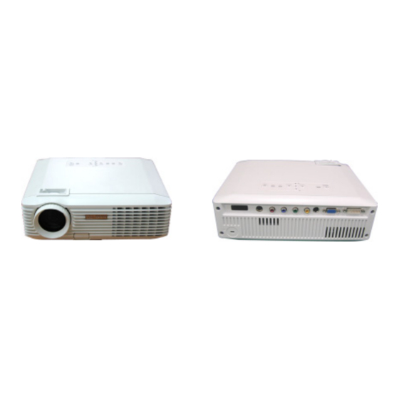
Chapter 2 Disassembly Procedure Equipment Needed Screw Bit(+) : 107 Hex Sleeves 5mm Screw Bit(+) : 101 Hex Sleeves 8mm Appearance The Rear Side The Front Side... -
Page 10: Removing Lamp Module
Removing Lamp Module Turn over the unit. Loosen 2 screws to remove Lamp Cover. Loosen 2 screws to pull out Lamp Module. Lamp Module Removing Rear Cover, Keypad Board, Top Cover and Main Board Unscrew 4 screws and 4 hex screws to remove Rear Cover. Hex screws Rear Cover... - Page 11 Pull out the Top Cover (as the blue arrow show) to remove it and then disconnect the FFC cable. Notice : Be careful, don’t put forth your strength too hard, in case the FFC cable breaks off. Unscrew 4 screws to remove Keypad Board and Control Key Rubber (under Keypad Board) Keypad Board FFC Cable...
-
Page 12: Removing 70X20 Axial Fan Module, Lamp Driver Module, Interrupt Switch And Lvps Module
Removing 70x20 AXIAL Fan Module, Lamp Driver Module, Interrupt Switch and LVPS Module Unscrew 2 screws to remove 70x20 AXIAL Fan Module. 70x20 AXIAL Fan Module Unscrew 4 screws and 2 hex spacers and disconnect the connector to remove Lamp Driver Module. - Page 13 Unscrew 7 screws (one of 7 screws is used by Grounding) to remove LVPS Module. Interrupt LVPS Plate Switch LVPS Module used by Grounding...
-
Page 14: Removing Front Cover Insert, Front Cover, Ir Receiver Board And Zoom Ring
Removing Front Cover Insert, Front Cover, IR Receiver Board and Zoom Ring Remove Front Cover Insert. Notice : Press two sides of the Front Cover Insert to lift it up. Unscrew one screw, then loosen 4 tenons inside of the Front Cover. Finally remove Front Cover. - Page 15 Remove Zoom Ring. Zoom Ring Front Cover Insert Take off the Mylar to remove IR Receiver Board. Front Cover IR Receiver Board...
-
Page 16: Removing Color Wheel Module And Engine Module
Removing Color Wheel Module and Engine Module Unscrew one screw to remove Color Wheel Module from Engine Module. Color Wheel Module Two tenons Notice : Please screw well (the two tenons should be stick out) when you assemble Color Wheel Module. Color Wheel Module Loosen one screw from Engine Base, then unscrew 6 screws to remove Engine Module. -
Page 17: Disassemble Engine Module
Disassemble Engine Module Unscrew 4 screws to remove HeatSink from Engine Module. Unscrew 4 screws to remove Formatter Board and DMD Chip from Engine Module. Unscrew 2 screws to remove Light Cut. Sponges DMD Chip DMD Thermal Pad Light Cut Formatter Board DMD Insulator Mylar DMD Heatsink Baker Plate... -
Page 18: Removing 50X20 Blower Fan Module, Elevator Module And Thermal Sensor Board
Removing 50x20 Blower Fan Module, Elevator Module and Thermal Sensor Board Unscrew 3 screws to remove 50x20 Blower Fan Module. 50x20 Blower Fan Module Unscrew one screw to remove Thermal Sensor Board. Thermal Sensor Board 2-10... - Page 19 Unscrew 9 screws to remove Bottom Base and Elevator Module. Turn over the Bottom Base and unscrew two screws to remove Elevator Foot. 2-11...
-
Page 20: Troubleshooting
Chapter 3 Troubleshooting Equipment Needed PC or pattern generator DVD player (Video, S-Video, Audio, HDCP/HDMI) Quantum Data 802B or CHROMA 2327 Main Procedure 3-2.1 No Power Ensure that the power cord and AC power outlet are securely connected. Check Lamp Cover and Interrupt Switch Ensure that all connectors are securely connected and haven’t broken. - Page 21 Check DMD Chip Check Engine Module 3-2.4 No Light on Ensure that all connectors are securely connected and haven’t broken. Check Lamp Module Check LVPS Check Lamp Driver Check Main Board 3-2.5 Mechanical Noise Check Color Wheel Check Fan Module Check LVPS Check Lamp Driver Check Engine Module...
- Page 22 3-2.9 Poor Uniformity/Shadow Ensure the projection screen without dirty Ensure the projection lens is clean Ensure the Brightness is within spec. Replace the Lamp if the Brightness is less than spec. Check Engine Module 3-2.10 Dead Pixel/Dust (Out of spec.) Ensure the projection screen without dirty Ensure the projection lens is clean Clean DMD Chip and Engine Module...
- Page 23 Check IR Receiver Board Check Main Board Control Panel Failed Check Cable FFC Check Keypad Board Check Main Board Function Abnormal Do “Factory Reset” of the engineering mode Do Firmware Upgrade Check Main Board Check DMD Board 3-2.15 Firmware/EDID Upgrade Failed Check hardware setting Firmware hardware setting (please refer to pages 5-1 and 5-2) EDID hardware setting (please refer to pages 6-1 and 6-2)
- Page 24 Notice : L E D S ta tu s M e a n in g O p e r a tio n P ro je c to r is c he c k if ne e d to A U T O Te m p + L a m p P o w e r c o rd p lug g e d B U R N - IN...
-
Page 25: Function Test And Alignment Procedure
Circumstance Brightness : Dark room less than 2.5 lux. Inspection Distance : 1.5m~3m for functional inspection Screen Size : 60 inches diagonal (wide) After repairing each H27, the unit should be burn-in for at least 4 hours. Notice : Set H27 in Burn-in Mode Press “Power”, “... -
Page 26: Test Display Modes And Pattern
Test Display Modes & Pattern 4-4.1 Compatible Modes (Analog and DVI) i t a l i b y t i t u l " 6 " 9... -
Page 27: Function Test Display Pattern
4-4.2 Function Test Display Pattern & / t s t s i . l a a i l f i n y t i l l u i n i l l u l l u l l a . l e l l u l l u . - Page 28 Figure 1. Fine Line Moire Figure 2. 16 Gray Scale Figure 3. 64 RGBW Scale Figure 4. Red Pattern Figure 5. Green Pattern Figure 6. Blue Pattern Figure 7. Full White Figure 8. Full Black...
- Page 29 Figure 9. Gary 30 Pattern Figure 10. Blue 60 Pattern Figure 11. Text Pattern Figure 12. Boundary Frame Figure 13. Gary 10 Pattern...
-
Page 30: Inspection Procedure
Inspection Procedure Factory Reset Please press “Power”, “ ”, “ ”, “Menu” on the projector control panel to enter the engineering mode, and then choose “Factory Reset” then choose “YES” and press enter to see if it works. This action will allow you to erase all end-user’s settings and restore the original setting. Firmware Version Test Signal : None Test Pattern : Service Mode... - Page 31 Connect the signal Choose “Video Calibration” function Color Performance and Contrast Test Signal : 854x480@60Hz Test Pattern : 64 RGBW scale Pattern and Gray 16 Pattern Please check and ensure if each color is normal and distinguishable If not, please return the unit to repair area. Screen Uniformity Test Signal : 854x480@60Hz Test Pattern : Full White Pattern...
- Page 32 Remote Controller Test Signal : Any Test Pattern : Any Cover Front IR Receiver up first and then test the remote controller. Cover Rear IR Receiver up first and then test the remote controller. Projection Mode Test Signal : Any Test Pattern : Any Test all projection modes to ensure the displays are normal or not.
- Page 33 Factory Reset After final QC step, we have to erase all saved change again and restore the factory defaults. Please press “Power”, “ ”, “ ”, “Menu” on the projector control panel to enter the engineering mode, and then choose “Factory Reset” then choose “YES” and press enter to see if it works.
-
Page 34: Firmware Upgrade Procedure
- Cable One Mini DIN 3-pin for RS232 - Power Cord Hardware Setup Procedure Connecting the RS232 Cable (One Mini DIN 3-pin) between PC/Laptop and H27 projector. Notice : Do not connect the H27 Power Cord in this procedure. RS232 Cable... -
Page 35: Firmware Upgrade Procedure
Firmware Upgrade Procedure Keep pressing "Menu" button and then plug in the H27 power cord until "LAMP", "TEMP" and "POWER" LED turn into the light. Notice : "LAMP" and "TEMP" LED turn into light first at the same time, and then "POWER"... - Page 36 Check the path that you installed "DLP Composer Lite" is correct or not. If the path is wrong, please click "Browse" to select the right path. Click "Communications" Choose "Projector Interface" as "Serial Port DDP2000" Select "COM1" port and then click "Configure"...
- Page 37 Choose "Baud Rate" as "115200", "Data Bits" as "8", "Stop Bits" as "1", "Parity" as "None", "RTS" and "CTS" as "Disable", and then click "OK". Click "OK" after selecting the right functions in "DLP Composer Perference". Click "Flash Loader"...
- Page 38 Click "Browse" to select the H27.IMG program, and then click "Open". Select the item "Skip Boot Loader Area (load all but the first 16KB)". This could prevent boot code to be damaged if you failed to download firmware. Notice : Please check the "Start" location of "Image Data (hex)" which marked as the yellow field.
- Page 39 Click "Reset Bus" and you will see the status change to "Bus Reset" Click "Start Download" and then click "Yes" to continue.
- Page 40 You will see the status is earsing elash ROM at first, and then downloading the new *Notice firmware. Download complete.
- Page 41 After upgrading the new firmware, please reconnect the H27 power cord and press "POWER" button to turn on the H27 projector. Press "POWER", " ", " ", "MENU" to enter the Engineering Mode. Check the Firmware version and do "Factory Reset".
-
Page 42: Ddc Key-In Procedure
EDID Fixture DVI to DVI Cable Power Adapter RS-232 Cable (Female to Female) VGA Cable Power Cord DDC Driver H27 Unit EDID Fixture P/N : 80.00001.001 RS-232 Cable (F-F) Power Adapter DVI to DVI Cable P/N : 42.86603.001 P/N : 47.53402.004 VGA Cable P/N : 42.56108.201... -
Page 43: Setup Procedure
Step2. Connect P1 of the fixture with COM1 of PC/Laptop by RS232 cable. Step3. Connect P2 or P4 of the fixture with VGA in port of H27 cable. Step4. Connect P3 of the fixture with DVI port of DVI-DVI cable. -
Page 44: Ddc Key-In Procedure
DDC Key-in Procedure Step 1. Execute “EDID” program. Step 2. Check the Com port is “COM1”, then click the “Model” item and choose the source file “DREAMY_H27_EDID2_110m” and then open it. - Page 45 Step 3. Check the Model is “DREAMY” and the Product is “OP 3339”. Step 4. Key in the Serial Number into the blank space, then click “Write” button.
- Page 46 Step 5. “Please connect to VGA” message is shown on the screen, then click “OK” button. Notice : “RUN” message will appear on the screen. Step 6. “Please connect to DVI” message is shown on the screen, then click “OK” button. Notice : “RUN”...
- Page 47 Step 7. When the H27 EDID program is finish, the “OK” message will appear on the screen. Step 8. Find Read function and choose “Analog” and “Trans” icon, then click “Read” button.
- Page 48 Step 9. Check EDID Informations will show the result and EDID Values will show Analog Values, then Message function will show “OK” message. Step 10. Find Read function and choose “Digital” and “Trans” icon, then click “Read” button.
- Page 49 Step 11. Check EDID Informations will show the result and EDID Values will show Digital Values, then Message function will show “OK” message. Step 12. Click “Exit” button to close the EDID program.
-
Page 50: Serial Number System Definition
EX: O82H433T0AAAA0002 This label “O82H433T0AAAA0002” represents the whole serial number for H27, including Ver. 1st of BIOS and Ver. 1 of PCB Board. Both mechanical and optical version are 1st. In addition, panel vendor is T. It’s produced on 33-week... -
Page 51: Board S/N Coding
Appendix B Board S/N Coding XXXXXXXXXX XXXX *Date Code Revision Vendor Code B. DMD BD C. MAIN BD *Date Code : Year(1 digit)+Week(2 digits) -
Page 52: Dlp Composer Lite Setup Procedure
Appendix C DLP Composer Lite Setup Procedure Step 1. Choose “DLP Composer Lite v3.6 Setup” program. Step 2. Click “Next” button. - Page 53 Step 3. Reading the “License Agreement” rules, choose “I accept and agree to be bound by all the terms and conditions of this License Agreement” icon, then click “Next” button.
- Page 54 Step 4. Click “Next” button. Step 5. Choose “All” icon, then click “Next” button.
- Page 55 Step 6. Click “Next” button. Step 7-1. The program is executing “Initializing” status.
- Page 56 Step 7-2. If the screen is show the below message, please choose “Ignore” button. Step 8. Click “Finish” button , then click “Yes” button to restart your computer.
-
Page 57: The Comparision Of Edid Fixture
Appendix D The Comparision of EDID Fixture How to identify EDID program? The new EDID program will show “Model” button, and the EDID fixture will printed “Generic” on the IC. EDID fixture EDID program The old EDID program will not show “Model” button, and the EDID fixture will printed “CMBDP11 M1”... -
Page 58: Reader's Response
Thank you for your backing our service manual up. In order to refine our content of the service manual and satisfy your requirement. We expect you can offer us some precious opinions for reference. Assessment: What do you think about the content after reading H27 Service Manual? t i n e l l t n I...