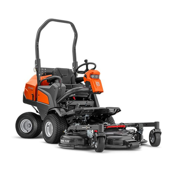
Husqvarna P 520D Operator's Manual
Lawn tractor
Hide thumbs
Also See for P 520D:
- Operator's manual (208 pages) ,
- Workshop manual (69 pages) ,
- Operator's manual (56 pages)
Table of Contents
Advertisement
Quick Links
Download this manual
See also:
Operator's Manual
Advertisement
Table of Contents
Troubleshooting

Related Manuals for Husqvarna P 520D


Summary of Contents for Husqvarna P 520D
- Page 1 Oper ator ′ s manual P 520D P 525D Please r ead the operator’s manual carefully and make sure you understand the E E E E n n n n g g g g l l l l i i i i s s s s h h h h...
-
Page 2: Key To Symbols
KEY TO SYMBOLS Symbols Ignition These symbols are on the machine and in the instructions. WARNING! Careless or incorrect use can Parking brake result in serious or fatal injury to the operator or others. Noise emission to the environment Please read the operator’s manual according to the European Community’s carefully and make sure you understand Directive. -
Page 3: Explanation Of Warning Levels
KEY TO SYMBOLS Explanation of warning levels Drive very slowly if no cutting unit is fitted The warnings are graded in three levels. WARNING! Risk of crush injuries! WARNING! Used if there is a risk of serious injury or death for the operator or damage to the surroundings if the instructions in the manual are not followed. -
Page 4: Table Of Contents
CONTENTS Contents MAINTENANCE AND SERVICE Maintenance schedule ............KEY TO SYMBOLS General ..................Symbols ................... Cleaning .................. Explanation of warning levels ..........Checking the engine’s cooling air intake ......... CONTENTS Cleaning the radiator cell package .......... Contents .................. Cleaning the air filter ............... Service journal Cleaning the engine and muffler .......... -
Page 5: Service Journal
Service journal Pre-delivery service 14 Tell customer about: The requirement and advantages of servicing the 1 Charge the battery for at least 4 hours at max. 5 machine according to the service plan amp. Servicing and the influence of this journal on the 2 Check coolant level and antifreeze. -
Page 6: Presentation
Dear Customer, Thank you for choosing a Husqvarna Rider. Husqvarna Riders are built to a unique design with a front-mounted cutting unit and a patented articulated steering. Riders are designed for maximum efficiency even in small or confined areas. The closely grouped controls and pedal-operated hydrostatic transmission also contribute to the performance of this machine. -
Page 7: Good Service
Good service Husqvarna products are sold all over the world and ensures that you, the customer, get the best support and service. For example, before this machine was delivered it was inspected and adjusted by your dealer. See the certificate in the Service Journal in this manual. -
Page 8: What Is What
WHAT IS WHAT? What is what on the machine? - Combi 132, Combi 155 1 Knob for seatback angle 14 Adjusting the cutting height 2 Product and serial number plate 15 Counter 3 Throttle trigger 16 Temperature gauge 4 Power outlet 17 Knob for adjustment of the seat suspension 5 Switch for the power outlet 18 Lever for longitudinal seat adjustment... -
Page 9: What Is What On The Machine
WHAT IS WHAT? What is what on the machine? - Combi 132 X, Combi 155 X 1 Knob for seatback angle 14 Cutting height indicator 2 Product and serial number plate 15 Counter 3 Throttle trigger 16 Temperature gauge 4 Power outlet 17 Knob for adjustment of the seat suspension 5 Switch for the power outlet 18 Lever for longitudinal seat adjustment... -
Page 10: Machine´s Safety Equipment
MACHINE´S SAFETY EQUIPMENT General Safety circuit The machine has a safety circuit that triggers whenever the WARNING! Never use a machine that has driver gets off the seat while the blades are engaged. The safety circuit is also tripped when the parking brake has not faulty safety equipment! been applied and the driver rises from the seat. -
Page 11: Speed Limiter
MACHINE´S SAFETY EQUIPMENT Speed limiter Parking brake The speed of the machine is steplessly regulated with two Operate the parking brake by moving the handle forwards. pedals. Pedal (1) is used to drive forwards, and pedal (2) to drive backwards. Checking the parking brake The machine is braked when the forward pedal is released. -
Page 12: Safety Belt
MACHINE´S SAFETY EQUIPMENT When the safety belt is not used, it must be wrapped around WARNING! The inside of the muffler contain the chair back and tightened. chemicals that may be carcinogenic. Avoid contact with these elements in the event of a damaged muffler. -
Page 13: Assembling And Adjustments
ASSEMBLING AND ADJUSTMENTS Safety when assembling and The Cutting Unit Components - Combi 132 X, Combi 155 X settings The components mentioned are: WARNING! The engine emits carbon monoxide, which is a colourless, poisonous gas. Do not use the machine in enclosed spaces. -
Page 14: Fitting The Cutting Head
ASSEMBLING AND ADJUSTMENTS Fitting the cutting head 6 Secure the front locking chain to the universal joint cover around the cross pipe. 1 Ride the machine to the cutting deck. 7 Make sure the rubber casing is folded over the front universal joint. -
Page 15: Removing The Cutting Unit
ASSEMBLING AND ADJUSTMENTS Fitting the cutting head Removing the cutting unit - Combi 132 X, Combi 155 X WARNING! Never leave the universal drive 17 Follow the instructions for 'Assembling the Cutting Deck' shaft of the machine with one end loose. If steps 1-16. -
Page 16: Seat Adjustment
ASSEMBLING AND ADJUSTMENTS Seat adjustment • Seatback angle is adjusted with the knob on the right side. WARNING! Take care so that hands are not trapped or injured by the locking hooks when the seat is folded back. WARNING! Do not adjust seat settings while driving. -
Page 17: Fuel Handling
FUEL HANDLING General The diesel engine injection system is very sensitive and can be damaged by the slightest contamination. Observe the greatest possible fuel cleanliness. Use only clean containers. WARNING! Running an engine in a confined or badly ventilated area can result in death •... -
Page 18: Operating
OPERATING General safety precautions • Serious accidents may occur if you fail to be on your guard for children in the vicinity of the machine. Children are often attracted to the machine and mowing. Never • Read all the instructions in this operator’s manual and on assume that children will remain where you last saw them. -
Page 19: Work Safety
OPERATING Work safety Driving the Rider • Make sure nobody else is in the vicinity of the machine when you start the engine, engage the drive or drive off. WARNING! Make sure that branches do not obstruct the pedals when mowing under •... -
Page 20: Adjusting The Cutting Height
OPERATING Adjusting the cutting height Transport position The cutting height can be adjusted to seven different • Stop the blades by pressing in the control for driving the positions. cutting unit. Select the required cutting height (1-7) using the cutting height adjusters. -
Page 21: Lights And Power Outlet
OPERATING Driving on slopes • When mowing, keep away from bushes and other objects. • Follow the manufacturer’s recommendations regarding Driving on slopes is one of the operations where the risk of wheel weights or counterbalance weights to increase the driver losing control of the machine or of it overturning is machine stability. -
Page 22: Transport And Storage
• Inspect the machine for worn or damaged parts and The P 520D and the P 525D has two valves, one valve for the tighten loose screws and nuts. front axle and one for the rear axle. •... -
Page 23: Starting And Stopping
STARTING AND STOPPING Before starting 3 Stop the blades by pressing in the control for driving the cutting unit. • Read the safety instructions and information concerning the placement of controls and functions before starting. • Perform daily maintenance before starting as set out in the Maintenance schedule. -
Page 24: Starting The Engine With A Weak Battery
STARTING AND STOPPING Starting when cold IMPORTANT! Never use a boost charger/start booster. If the engine fails to start due to the cold, repeat ignition and Use only conventional battery chargers. Always disconnect attempt to re-start. Start gas or ether must not be used. the charger before starting the engine. -
Page 25: Maintenance And Service
MAINTENANCE AND SERVICE Maintenance schedule WARNING! No service procedures must be conducted on the engine or cutting unit unless: The engine is switched off. The parking brake is applied. The ignition key is removed. The cutting unit is disengaged. The following is a list of the maintenance which should be conducted on the machine. For those points not described in this manual, visit an authorised service workshop. -
Page 26: General
MAINTENANCE AND SERVICE General Cleaning the radiator cell package Service Clean the radiator with compressed air. Use compressed air blown from the engine compartment through the cell package Low season is the most suitable time to perform a service or and back. -
Page 27: Cleaning The Engine And Muffler
MAINTENANCE AND SERVICE Cleaning the engine and muffler Cover Plate Keep the engine and muffler free from grass cuttings and dirt. Clipping debris soaked in fuel or oil on the engine means increased risk of fire and impaired cooling. Allow the engine to cool before cleaning. If the dirt is mixed with oil, remove it using a degreasing agent otherwise just water and a brush. -
Page 28: Adjusting The Parking Brake
MAINTENANCE AND SERVICE Adjusting the parking brake 6 Insert the new bulbs. Make sure you use your thumb to support the front. Make sure the parking brake is properly adjusted by placing the machine on a slope. Apply and lock the parking brake. When the machine does not stand still, the parking brake should be adjusted according to the following. -
Page 29: Restoring From Service Position
MAINTENANCE AND SERVICE 5 Lower the cutting unit to the lowest position. The cutting 13 Secure the cutting unit with the safety belt, which is stored unit now hangs free at the back. in the storage compartment under the seat. 6 Remove the universal drive shaft completely. -
Page 30: Cutting Height And Tilt Angle Adjustment
MAINTENANCE AND SERVICE Cutting height and tilt angle Tilt angle - Combi 132, Combi 155 adjustment. • Place the machine on a flat surface. When a cutting unit is installed the cutting height and tilt angle • Check the tyre pressures. The tyre pressure should be 1.5 need to be adjusted bar/150 kPa/22 PSI for all wheels The adjustment must be made in the stated order. - Page 31 MAINTENANCE AND SERVICE Cutting height - Combi 132 X, Combi 155 X Tilt angle - Combi 132 X, Combi 155 X • Place the machine on a flat surface. WARNING! Keep unauthorised persons at a • Check the air pressure in the tyres The tyre pressure distance.
-
Page 32: Replacing The Cutting Unit Belts
MAINTENANCE AND SERVICE Replacing the cutting unit belts • Lock the blade with a wooden block. Loosen the blade bolt and remove the blade bolt, the washers and the blade. WARNING! Protect your hands with gloves There is a risk of crush injuries when working with the belt. -
Page 33: Adjustment Of Pto Belts
MAINTENANCE AND SERVICE Adjustment of PTO belts 8 Pull the new belts through the gap between the spacer ring and the hydraulic pump. 1 Tighten screw (4) until the sleeve bottoms against the frame bracket. Tighten lock nut (3) whilst holding screw (4) firmly. -
Page 34: Change Coolant
The antifreeze must be intended for alloy engines. The muffler is designed to keep noise levels to a minimum and to direct exhaust fumes away from the user. Your Husqvarna supplier can provide the right type of antifreeze. • Check regularly that the muffler is complete and secured correctly. -
Page 35: Check The Battery
MAINTENANCE AND SERVICE Check the battery Replacing the air filter WARNING! Lead-acid batteries produce WARNING! The exhaust system is hot. Let it explosive gases. Avoid sparks, open flames cool before starting to replace the air filter. and smoking close to batteries. Always wear protective glasses in the If the engine seems to lack power or does not run smoothly vicinity of batteries. -
Page 36: The Cutting Unit Bevel Gear
MAINTENANCE AND SERVICE The cutting unit bevel gear The oil filler is on the valve cap. Check the oil level Check the oil level when the cutting deck is in its lowest position. • Insert a clean metal rod (approx. Ø3 mm) through the filler plug. -
Page 37: Changing The Oil Filter
MAINTENANCE AND SERVICE Check the hydraulic system oil level 7 If necessary fill so that the oil comes up to the FULL mark on the dipstick. The oil and filter should be changed by an authorised service 8 Run the engine warm, then check that there is no leakage representative, as described in the Workshop Manual. -
Page 38: Lubrication
Lubrication Lubrication schedule QUICK MAINTENANCE GUIDE First service after 25 hours X-Variants 0,9L 3,0L 3,3L Front & Rear ANTIFREEZE = TIRE TRANSMISSION OIL 10W 50 API SM SAE 80W/90 = 80cl (3oz) SAE 10W 50 API SM = 8L 50% Propylene Glycol PRESSURE = Front &... -
Page 39: Accessories
Lubrication Accessories Lift cylinder Lubrication or other maintenance of optional equipment or • Remove the service hatch. accessories is not described in this manual. This equipment too, naturally, requires maintenance. See the manuals for the • 2 grease nipples, one on each side. Lubricate with a respective accessories for instructions. -
Page 40: Joint Bearing
Lubrication Joint bearing Lubricating the cables • Grease the waist section of joint bearing Lubricate with a • Remove the cable´s rubber casing when lubricating. grease gun until the grease is forced out. • Grease both ends of the cables and move the controls to end stop positions when lubricating. -
Page 41: Troubleshooting Schedule
Troubleshooting schedule Problem Cause There is no fuel in the fuel tank Air in fuel system Engine does not start Incorrect fuel type Ignition system inoperative Serious engine damage Battery flat Poor contact affecting the battery terminal cable connections, ignition lock, or starter Power take off (PTO) activated Air in fuel system... -
Page 42: Troubleshooting Schedule
Troubleshooting schedule One or more battery cells faulty Poor contact on the battery terminal cable connectors Defective alternator Battery does not charge Alternator belt broken or slipping Wires to the alternator broken Defective battery maintenance Sulphated battery Blades are loose Damaged universal joint Engine is loose The hydraulic pump is loose... -
Page 43: Technical Data
TECHNICAL DATA P 520D P 525D Dimensions Unladen weight excluding cutting unit, kg/lb 627 / 1382 677 / 1492 Tyre dimensions 18 x 8,5 x 8 20x10x10 Air pressure, rear - front, kPa / bar / PSI 150/1,5/22 150/1,5/22 Engine... -
Page 44: Technical Data
Article number 5861988-10 5441758-10 Blade length, mm/inch 490 / 19,3 563 / 22.2 Technical specifications for sound and vibration levels P 520D P 525D Combi 132 Combi 155 Combi 132 Combi 155 Noise emissions (see note 2) Sound power level, measured dB (A) -
Page 45: Ride-On Mower Dimensions
TECHNICAL DATA Ride-on mower dimensions P 520D P 525D 897 mm 904 mm 1110 mm 1139 mm 120 mm 145 mm 821 mm 828 mm 1034 mm 1063 mm 1301 mm 1326 mm 474 mm 499 mm 644 mm 644 mm... -
Page 46: Ec Declaration Of Conformity
EC Declaration of Conformity (Applies to Europe only) Husqvarna AB, SE-561 82 Huskvarna, Sweden, tel.: +46-36-146500, hereby declares that Husqvarna P 520D and P 525D from 2015’s serial numbers and onwards (the year is clearly stated in plain text on the rating plate with subsequent serial number), complies with the requirements of the COUNCIL’S DIRECTIVE:... - Page 48 Original instructions 1157507-26 ´®z+YRh¶6K¨ ´®z+YRh¶6K¨ 2015-03-18...