
Related Manuals for Motrec E-242HD


Summary of Contents for Motrec E-242HD
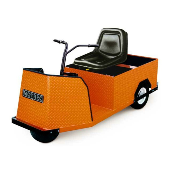
- Page 1 E-242HD OPERATOR AND MAINTENANCE MANUAL SPARE PARTS LISTS INCLUDED SERIAL NUMBER : 1035396 & UP Printed in Canada...
- Page 2 To initiate warranty coverage on any MOTREC vehicle, the Dealer must complete and return the “Sales/Installation Report” to MOTREC within 30 days after delivery to the Original Retail Purchaser; or within 90 days after the delivery date to the Dealer, which ever occurs first. Failure to follow these procedures will result in considering the warranty coverage effective as of the shipment date from the factory.
-
Page 3: Table Of Contents
BATTERY CHARGER ELECTRICAL TROUBLESHOOTING CURTIS SPEED CONTROLLER WIRING : STANDARD CONFIGURATION DIAGNOSTICS AND TROUBLESHOOTING TROUBLESHOOTING CHART LED DIAGNOSTICS PROGRAMMING PARAMETERS – E-242, E-242HD, E-250 CURTIS PMC MOTOR CONTROLLER WIRING : STANDARD CONFIGURATION MAINTENANCE AND ADJUSTMENT SPARE PARTS BODY DIFFERENTIAL MECHANICAL DRUM BRAKES... -
Page 4: Instructions
Instructions INSTRUCTIONS - 4 -... -
Page 5: Safety Warnings For Operators
Instructions SAFETY WARNINGS FOR OPERATORS FAILURE TO OBEY THE FOLLOWING SAFETY RULES MAY RESULT IN SEVERE INJURY. It is the responsibility of the owner of this vehicle to train operators to ensure that they understand the operating characteristics of this vehicle, including training in vehicle stability, and obey the following safety rules and guidelines. -
Page 6: Operating Instructions
Instructions OPERATING INSTRUCTIONS It is the responsibility of the owner of this vehicle to ensure that the operator understands the operating characteristics of this vehicle, and obeys the safety instructions in this manual and ANSI/ITSDF B56.8 & 9 Standards. Do not drive this vehicle unless you are a certified operator as required by OSHA. BEFORE TURNING ON KEYSWITCH Set to neutral, set parking brake, check for visible damage, check brake pedal. -
Page 7: Maintenance
Maintenance MAINTENANCE - 7 -... -
Page 8: Safety Warnings For Service Technicians
Maintenance SAFETY WARNINGS FOR SERVICE TECHNICIANS FAILURE TO OBEY THE FOLLOWING SAFETY RULES MAIN RESULT IN SEVERE INJURY. Owner shall comply with OSHA and ANSI/ITSDF B56.8 & B56.9 Standards for vehicle maintenance. Only qualified and authorized personnel shall be permitted to maintain, repair, adjust and inspect carriers, vehicles, tractors, and batteries. - Page 9 Maintenance Do not try to increase motor speed by changing parameter settings in the speed controller; it can cause accident and severe damage to the motor. SEPEX speed controls are protected by a diode in the power circuit to filter inductive loads in the event of a sudden power interrupt.
-
Page 10: Decals And Labels
Maintenance DECALS AND LABELS ! CAUTION ! The images included in this section depict the decals/markings installed on the vehicle. It is of the utmost importance that theses decals/markings remain unaltered and readable. Else, the sticker or the part baring the marking has to be replaced. Dashboard security warning label: General security warning label: # 5100000002... -
Page 11: Periodic Maintenance Checklist
Maintenance PERIODIC MAINTENANCE CHECKLIST REVISION 080206 ! WARNING ! Maintenance operations must be made by properly trained service technicians. Keep clear from moving parts such as tires, sheaves and motor. Check for all EE protections, when applicable, and keep cables and wires clear from mechanical and rubbing action Batteries contain sulphur acid that can cause severe burns on skin or eyes. -
Page 12: Accelerator
Maintenance ACCELERATOR GEAR Remove the cover. Backlash between gears must be reduced to a minimum by sliding holder; use locktite 262 to lock the three screws. When the plastic gear is fully depressed a small backlash must remain between the gears. When the plastic gear is released its rear portion must not exceed the pedal case. -
Page 13: Belt Installation And Tensioning
Maintenance BELT INSTALLATION AND TENSIONING INSTALLATION Adjust the sprockets using a straight edge. Slide up the edge on the larger pulley until it contacts the smaller pulley. Properly adjusted pulleys will provide three points of contact. Properly aligned pulleys will provide four points of contact. Tighten setscrews and recheck alignment. TENSIONING Check the force F required to provide a deflection of 1/8 in. -
Page 14: Mechanical Brakes
Maintenance MECHANICAL BRAKES Revision 2008-02-06 REPLACING THE BRAKE SHOES ON SELF ADJUSTING DRUM BRAKES: raise the vehicle until the rear tires lift-off the floor and install two jack stands on rear; remove drums; replace brakes shoes and springs if linings are 1/16” (2mm) thick or less disassemble and clean the adjusting screw assembly;... -
Page 15: Battery Maintenance
Maintenance BATTERY MAINTENANCE ! WARNING ! It is the responsibility of the owner of this vehicle to ensure that the service technicians are properly trained, read and obey the safety rules and guidelines in this manual (ANSI B56). Maintenance operations must be made by properly trained service technicians only. Before any maintenance work, park the vehicle on a flat level surface, turn off all the switches, set to neutral, remove the key, lift the wheels off the ground and secure with jack stands of adequate capacity. - Page 16 Maintenance BATTERY MOUNTING A loose battery increases damaging effects of vibrations and is more prone to short out. BATTERY DISCHARGE LIMIT Discharging below a 20% state of charge cuts down the battery life and the number of cycles available. At 20% state of charge, specific gravity of 6V battery should be 1180; and 1220 for industrial battery. CHARGING AREA Always charge battery in a well ventilated area set for and approved for charging.
-
Page 17: Battery Charger
Maintenance BATTERY CHARGER ! WARNING ! Always unplug the AC and DC electrical cords before attempting any repairs to the charger. CHARGER DOES NOT TURN ON: Dc cord of portable chargers must be disconnected from batteries after every charge to restart; Check dc fuse links;... -
Page 18: Electrical Troubleshooting
Maintenance ELECTRICAL TROUBLESHOOTING ! WARNING ! Maintenance work must be performed by trained service technicians only. It is the responsibility of the owner of this vehicle to ensure that the services technicians are properly trained, understand and obey the safety rules and guidelines (ANSI B56). All service technicians must read and understand the maintenance warning section in this manual. - Page 19 Maintenance REVERSE ONLY On a SEPEX motor control, check the forward signal input on the controller. On a series wound motor control, a bad forward contactor is the most probable cause of the problem. Switch to forward and check the voltage on the forward control wire. If not B+, replace the F/R switch. If B+, turn off the key switch, disconnect batteries, disconnect power terminals on the F/R contactors, check the resistance across N.C.
- Page 20 Maintenance NO MOTION Make sure that the PMC surface is clean and dry; check the terminal areas. Dust Particles or acid contamination, can create current leaks and cause a PMC malfunction. Check F/R switch Turn on the key switch and set to forward. Check voltage between the forward terminal and the –...
-
Page 21: Curtis Speed Controller
Curtis Speed Controller CURTIS SPEED CONTROLLER - 21 -... - Page 22 MANUAL 1 2 4 3 Generation 2 MultiMode™ MOTOR CONTROLLER © 2002 CURTIS INSTRUMENTS, INC. DESIGN OF CURTIS PMC 1200 SERIES CONTROLLERS PROTECTED BY U.S. PATENT NO. 4626750. CURTIS INSTRUMENTS, INC. 200 Kisco Avenue 1243 2 Manual, p/n 37044 Mount Kisco, NY 10509 USA Rev.
-
Page 23: Wiring: Standard Configuration
2 — INSTALLATION & WIRING: Controller for the M8 bolts. The maximum bolt insertion depth below the surface of the bus bar is 1.3 cm (1/2"). Bolt shafts exceeding this length may damage the controller. The torque applied to the bolts should not exceed 16.3 N·m (12 ft-lbs). Two 1/4"... -
Page 24: Diagnostics And Troubleshooting
7 — DIAGNOSTICS & TROUBLESHOOTING DIAGNOSTICS AND TROUBLESHOOTING The 1243 2 controller provides diagnostics information to assist technicians in troubleshooting drive system problems. The diagnostics information can be obtained by observing the appropriate display on the handheld programmer, the fault message displayed on the Spyglass gauge, the fault codes issued by the Status LED, or the fault display driven by the controller’s fault outputs (Fault 1 and Fault 2). -
Page 25: Troubleshooting Chart
7 — DIAGNOSTICS & TROUBLESHOOTING Table 7 TROUBLESHOOTING CHART PROGRAMMER FAULT CATEGORY CODE LCD DISPLAY POSSIBLE CAUSE FAULT CLEARANCE NO KNOWN FAULTS 1. Abnormal vehicle operation causing Cycle KSI. If problem CURRENT SHUNT FAULT high current spikes. persists, replace controller. 2. - Page 26 7 — DIAGNOSTICS & TROUBLESHOOTING Table 7 TROUBLESHOOTING CHART, cont’d PROGRAMMER FAULT CATEGORY CODE LCD DISPLAY POSSIBLE CAUSE FAULT CLEARANCE 1. Battery voltage < undervoltage cutback. When voltage rises above LOW BATTERY VOLTAGE 2. Corroded battery terminal. undervoltage cutoff point. 3.
-
Page 27: Led Diagnostics
7 — DIAGNOSTICS & TROUBLESHOOTING STATUS LED DIAGNOSTICS A Status LED is built into the 1243 2 controller. It is visible through a window in the label on top of the controller. This Status LED displays fault codes when there is a problem with the controller or with the inputs to the controller. -
Page 28: Programming Parameters - E-242, E-242Hd, E-250
Curtis Speed Controller PROGRAMMING PARAMETERS – E-242, E-242HD, E-250 ! WARNING ! The owner of this vehicle shall ensure that the service technicians are qualified, properly trained and obey the safety rules and guidelines in OSHA and ANSI B56 regulations, and in this manual. -
Page 29: Curtis Pmc Motor Controller
Curtis Speed Controller CURTIS PMC MOTOR CONTROLLER - 29 -... - Page 30 M A N U A L 1204/5 MOTOR CONTROLLERS © 1999 CURTIS INSTRUMENTS, INC. DESIGN OF CURTIS 1200 SERIES CONTROLLERS PROTECTED BY U.S. PATENT NO. 4626750. CURTIS PMC 235 East Airway Boulevard 1204 / 1205 Manual Livermore, California 94568 USA p/n 98690, Rev.
-
Page 31: Wiring : Standard Configuration
W IRIN G WIRING CONNECTIONS: Low Current Three 1/4" push-on terminals are provided throttle for the low current connections to the KSI inputs and throttle inputs. For the control wiring, 0.75 mm (#18 AWG) vinyl insulated stranded wire is rec- ommended. - Page 32 WIRING CONTROL WIRING PEDAL KEYSWITCH INTERLOCKS FUSE MICROSWITCH POLARITY PROTECTION DIODE POWER WIRING MAIN FUSE PRECHARGE RESISTOR (250 Ω, 5 W) POTBOX – Fig. 6 Basic wiring configuration, Curtis PMC 1204/1205 controller. WIRING: SERIES MOTORS Figure 6 is a schematic of the configuration shown in Figure 5. Wired this way, the vehicle will plug brake if the direction is changed with the vehicle moving and the throttle applied.
-
Page 33: Maintenance And Adjustment
MAINTENANCE & ADJUSTMENT MAINTENANCE & ADJUSTMENT Curtis 1204/1205 controllers and potboxes require only minimal main- tenance if properly installed. : The controllers are sealed and thus NOTE are not field serviceable. CONTROLLER Maintenance It is recommended that the following two steps be performed occasion- ally. - Page 34 MAINTENANCE & ADJUSTMENT Adjustment On some models, the plug braking current and acceleration rate settings are adjustable. On these adjustable controllers, the adjustment pots are located as shown in Figure 18. Fig. 18 Adjustment pots. ACCELERATION RATE ADJUST PLUG CURRENT ADJUST (CW = higher plug current) (CW = faster acceleration) Use the following adjustment procedure.
-
Page 35: Spare Parts
Spare Parts SPARE PARTS - 35 -... -
Page 36: Body
Spare Parts BODY REF. PART NO DESCRIPTION 240001 BODY 120003 TRIM 240003 CARGO DECK 2400050 INSTRUMENT PANEL 240501 SEAT CUSHION 240502 BACKREST CUSHION 240503 FRAME 2401017 GARD 240101 7" REAR FOOTSTEP 240107 12" REAR FOOTSTEP 2401004 12" REAR FOOTSTEP WITH CLEVIS 2401005 12"... -
Page 37: Differential
Spare Parts DIFFERENTIAL - 37 -... - Page 38 Spare Parts REF. PART NO DESCRIPTION SHAFT 242052 BEFORE SERIAL # 0611210, 0611204 AND 0611207 2420014 BETWEEN SERIAL # 0611210, 1013902 2173240001 SERIAL # 1013902 & UP 2420021 LOCK 242054 BOLT OIL SEAL 242056 BEFORE SERIAL # 0611210 2420011 SERIAL # 0611210 & UP BEARING 242057 BEFORE SERIAL # 0611210...
-
Page 39: Mechanical Drum Brakes
Spare Parts MECHANICAL DRUM BRAKES MANUAL ADJUSTEMENT, OLD SELF ADJUSTEMENT, NEW SERIAL NUMBER 0707070 & + REF. PART NO DESCRIPTION REF. PART NO DESCRIPTION 242051 DRUM 2123242001 DRUM 4-BOLT BOLT, 5/16-NC X 3/4 2123240001 DRUM 5-BOLT 242841 BACK PLATE 2413002 BACKING PLATE LH 242842 BRAKE SHOE... -
Page 40: Brake Controls
Spare Parts BRAKE CONTROLS REF. PART NO DESCRIPTION 242801 PEDAL RUBBER 242802 PARKING BRAKE CONTROL 242803 COTTER PIN PIN ¼ 242806 SPING 242830 OLD BRAKE LEVER 2416006 NEW BRAKE LEVER 242831 PIVOT BOLT 3/8-NC X 3 242816 SPRING 242817 LUBRICATION FITTING PIN 3/8 X 1 2416017 PIVOT, DRAWBAR... -
Page 41: Steering Assembly
Spare Parts STEERING ASSEMBLY REF. PART NO DESCRIPTION REF. PART NO DESCRIPTION 241430 STEERING WHEEL ASS. 241431 SPROKET BOLT 3/8-NC X 3 2430010 CHAIN LOCKNUT 7/16-NC 241001 AXLE 241406 BALL BEARING (2.44 O.D.) 241002 SEAL 281406 BALL BEARING (3.31 O.D.) 241003 TAPER BEARING 241427... -
Page 42: Steering Wheel
Spare Parts STEERING WHEEL REF. PART NO DESCRIPTION 241430 STEERING WHEEL ASS. 481453 COVER 481452 481451 STEERING WHEEL 481454 SPRING PIN 481437 BUSHING 2830011 SUPPORT 2830004 SHAFT - 42 -... -
Page 43: Motor And Drive
Spare Parts MOTOR AND DRIVE COMMON PARTS DESCRIPTION PART # DESCRIPTION PART # 1 PULLEY 262424 8 MOTOR BASE, FORD Contact manuf. 2 V BELT 242431 BELT TENSIONER 2152002 3 PULLEY 3651001 9 SEAL 484001 4 BELT, EAGLE 3651002 10 BEARING 484003 5 MOTOR BASE, GM Contact manuf. -
Page 44: Rear Axle Frame
Spare Parts REAR AXLE FRAME REF. PART NO DESCRIPTION 242621 SHOCK ABSORBER 242622 COIL SPRING SPRING RETAINER 242623 BEFORE SERIAL # 1012672 & UP 2440008 SERIAL # 1012672 & UP 242602 BUSHING BOLT 5/8-NC X 4 LOCK NUT 5/8-NC LOCK NUT ½-NC - 44 -... -
Page 45: Electrical Diagram - Sepex Main Circuit
Spare Parts ELECTRICAL DIAGRAM – SEPEX MAIN CIRCUIT DIAGRAMME ÉLECTRIQUE – CIRCUIT PRINCIPAL SEPEX - 45 -... -
Page 46: Electrical Diagram - Series Main Circuit
Spare Parts ELECTRICAL DIAGRAM – SERIES MAIN CIRCUIT DIAGRAMME ÉLECTRIQUE – CIRCUIT PRINCIPAL SÉRIES - 46 -... -
Page 47: Accessories - No Dc/Dc Converter
Spare Parts ACCESSORIES – NO DC/DC CONVERTER ACCESSOIRES – SANS CONVERTISSEUR DC/DC - 47 -... - Page 48 BRAKE LIGHT SWITCH 246207 EMERGENCY PUSH BUTTON 3109800001 EMERGENCY PUSH BUTTON LABEL 3109800006 HOUR METER CONNECTOR SPEED CONTROL CONNECTOR MAIN CONTACTOR 246111 Y2.A,B F/R CONTACTOR 246230 F/R BUSSBARS 2469003 STATIC STRAP 2450001 * Consult Motrec Illustrated parts - 48 -...
-
Page 49: Battery Configurations - 24V
Spare Parts BATTERY CONFIGURATIONS - 24V CONFIGURATIONS DES BATTERIES – 24V - 49 -... -
Page 50: Built-In 25A Charger
Spare Parts BUILT-IN 25A CHARGER Parts list for LESTRONIC II charger MODEL 07210 TYPE 24LC25-8ET 115 VAC 60 Hz PART NO DESCRIPTION 10044S CASE ASSEMBLY 11576S TRANSFORMER ASSEMBLY 02390S CAPACITOR, 6.0 MFD, 660 VAC 16354S HEATSINK ASSEMBLY, WITH DIODES 08776S FUSE ASSEMBLY 04127S AMMETER, 0-30 AMP... -
Page 51: Portable 40A Charger
Spare Parts PORTABLE 40A CHARGER Parts list for LESTRONIC II charger MODEL 9513 TYPE 24LC40-8ET 115 VAC 60 Hz PART NO DESCRIPTION 09511S CASE ASSEMBLY 09512S TRANSFORMER ASSEMBLY 09041S HEATSINK ASSEMBLY, WITH DIODES 08849S DIODE ASSEMBLY 16823S AMMETER 09662S ELECTRONIC TIMER ASSEMBLY (4483D RELAY) 08774S FUSE ASSEMBLY 02390S... -
Page 52: Portable 25A Charger
Spare Parts PORTABLE 25A CHARGER Parts list for LESTRONIC II charger MODEL 13110 TYPE 24LC25-8ET 115 VAC 60 Hz PART NO DESCRIPTION 15114S CASE ASSEMBLY 13145S TRANSFORMER ASSEMBLY 08385S HEATSINK ASSEMBLY, WITH DIODES 08811S DIODE ASSEMBLY 04127S AMMETER 12955S ELECTRONIC TIMER ASSEMBLY (4483D RELAY) 02390S CAPACITOR, 6.0 MFD, 660 VAC 08776S... -
Page 53: Built-In/Portable Charger Model 16370
Spare Parts BUILT-IN/PORTABLE CHARGER MODEL 16370 Parts list for MODEL 16370 TYPE 24EL20-8ET 100-125 or 200-250 VAC / 50-60 Hz PART NO QTY. DESCRIPTION 20933S CASE ASSEMBLY 16375S TRANSFORMER ASSEMBLY 16369S AMMETER 20919S HEATSINK ASSEMBLY, W/ SCR 23224S SCR ASSEMBLY 16450S ELECTRONIC TIMER ASSEMBLY 19233S... -
Page 54: Delta-Q Hf Charger
Spare Parts DELTA-Q HF CHARGER PART NO DESCRIPTION 24V CHARGER ( U.S. BATTERY ) 3102240002 3102240003 24V CHARGER ( LIFELINE BATTERY ) 3102240004 24V CHARGER ( GEL 180AH BATTERY) 3102240005 24V CHARGER ( 27TM BATTERY ) 36V CHARGER ( U.S. BATTERY ) 3102302001 3102302002 36V CHARGER ( LIFELINE BATTERY ) - Page 55 Spare Parts - 55 -...
- Page 56 Spare Parts - 56 -...
-
Page 57: Motrec Illustrated Accessories
Spare Parts MOTREC ILLUSTRATED ACCESSORIES Headlight Red Tail/Brake light Left: 3111480003 Strobelight, polemount Housing: 3069012R Horn button VIP Right: 3111480004 Amber 12-80V: 3116000001 Bulb 12V: 3117240001 2330014 Bulb H/L: 3117480001 Red 12-80V: 2469001 Bulb Turn: 3117480003 Blue 12-80V: 3690008 Bulb Mark:... - Page 58 Spare Parts Pantograph wiper blade Wiper motor 246233 12V: 3113000001 24V: 486211 Analog Voltmeter Headlamp 12V: 3111250002 12V : 3069007 24V : 2469002 36-48V : 3669002 Cab heater 12V: 3103300001 Wiper arm 2800000001 36V: 3669008 Headlamp 48V: 4869020 12V: 3111300001 Bulb 12V: 3111300002 HOBBS Gauge...
-
Page 59: Battery Discharge Indicator (Hobbs)
Spare Parts BATTERY DISCHARGE INDICATOR (HOBBS) This indicator monitors : the residual capacity of batteries; operating hours; status of service down counter. The residual capacity of the battery is monitored via an 8-LED bar display. When the left red LED lights, the batteries must be charged to avoid damage.