Table of Contents
Advertisement
Statement:
This manual is the intellectual property of Foxconn, Inc. Although the
information in this manual may be changed or modified at any time,
Foxconn does not obligate itself to inform the user of these changes.
Trademark:
All trademarks are the property of their respective owners.
Version:
User's Manual V1.0 for MCP61PM2MA/MCP61SM2MA/MCP61VM2MA
motherboard.
Symbol description:
Note: refers to important information that can help you to use motherboard
better.
Attention: indicates that it may damage hardware or cause data loss,
and tells you how to avoid such problems.
Warning: means that a potential risk of property damage or physical
injury exists.
More information:
If you want more information about our products, please visit Foxconn's
website:
http://www.foxconnchannel.com
This product and its accessories are produced after 13th Aug., 2005 and
comply with the W EEE2002/96EC directive.
Advertisement
Table of Contents

Related Manuals for Foxconn MCP61PM2MA


Summary of Contents for Foxconn MCP61PM2MA
- Page 1 This manual is the intellectual property of Foxconn, Inc. Although the information in this manual may be changed or modified at any time, Foxconn does not obligate itself to inform the user of these changes. Trademark: All trademarks are the property of their respective owners.
-
Page 2: Declaration Of Conformity
HON HAI PRECISION INDUSTRY COMPANY LTD 66 , CHUNG SHAN RD., TU-CHENG INDUSTRIAL DISTRICT, TAIPEI HSIEN, TAIWAN, R.O.C. declares that the product Motherboard MCP61PM2MA/MCP61SM2MA/MCP61VM2MA is in conformity with (reference to the specification under which conformity is declared in accordance with 89/336 EEC-EMC Directive) þ... - Page 3 Declaration of conformity Trade Name: WinFast Model Name: MCP61PM2MA/MCP61SM2MA/MCP61VM2MA Industry Inc. Responsible Party: Address: 458 E. Lambert Rd. Fullerton, CA 92835 Telephone: 714-738-8868 Facsimile: 714-738-8838 Equipment Classification: FCC Class B Subassembly Type of Product: Motherboard Manufacturer: HON HAI PRECISION INDUSTRY...
-
Page 4: Table Of Contents
Table of Contents Chapter Product Introduction Main Features ..................2 Layout ...................... 4 Rear Panel Ports ................... 5 Chapter Installation Instructions CPU ......................7 Memory ....................8 Power Supply ..................9 Other Connectors ................10 Expansion Slots ................... 16 Jumpers ....................17 Chapter BIOS Description Enter BIOS Setup ................. - Page 5 Table of Contents Chapter Driver CD Introduction Utility CD content ................. 39 Installing Drivers .................. 40 Installing Utilities ................. 40 Chapter Directions for Bundled Software TIGER ONE .....................42 Fox LiveUpdate ..................48...
- Page 6 Attention: 1. Attach the CPU and heatsink using silica gel to ensure full contact. 2. It is suggested to select high-quality, certified fans in order to avoid damage to the motherboard and CPU due high temperatures. 3. Never turn on the machine if the CPU fan is not properly installed. 4.
- Page 7 This manual is suitable for motherboard of MCP61PM2MA/ MCP61SM2MA/MCP61VM2MA. Each motherboard is carefully designed for the PC user who wants diverse features. -L with onboard 10/100M LAN (Default is omitted.) -K with onboard Gigabit LAN -6 with 6-Channel audio (Default is omitted.)
-
Page 8: Main Features
Chapter Thank you for buying W inFast MCP61PM2MA/MCP61SM2MA/ MCP61VM2MA series motherboard. This series of motherboard is one of our new products, and offers superior performance, reliability and quality, at a reasonable price. This motherboard adopts the advanced nVIDIA MCP61P / MCP61S / MCP61V chipset, providing users a computer platform with a high inte- gration-compatibility-performance price ratio. - Page 9 Chapter 1 Product Introduction Main Features Size · mATX form factor of 9.6 inch x 9.6 inch Microprocessor Microprocessor · Supports socket AM2 for AMD ® Athlon 64X2 Dual Core,Athlon 64 and Sempron processors · Supports HyperTransport up to 2000MT/s Chipset ·...
-
Page 10: Chapter 1 Product Introduction
PCI-E(16X) slot Supports 2 GB/sec bandwidth (supported on MCP61SM2MA only) PCI-E(16X) slot Supports 250MB/sec bandwidth (supported on MCP61VM2M only) ·MCP61PM2MA/MCP61SM2MA don’t support some old version ATi graphics cards,such as ATi X300, X550,X700,X800 series graphics cards. ·Low power consumption and power management features Green Function ·... -
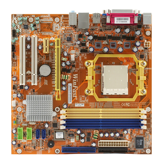
Page 11: Layout
Chapter 1 Product Introduction Layout 14 15 16 1. CPU_Fan Connector 13. Front USB Connectors 2. PCI Express x16 Slot 14. Chassis Intruder Connector 3. PCI Express x1 Slot 15. SATA II Connector (optional) 4. PCI Slots 16. Speaker Connector 5. -
Page 12: Rear Panel Ports
Chapter 1 Product Introduction Rear I/O Ports This motherboard provides the ports as below: For -6 models Parallel Port 1394 Connector Connector (Printer Port) (optional) Line-in jack PS/2 Mouse Connector Line-out jack PS/2 Keyboard Microphone jack Connector Serial Port VGA Port USB 2.0 Ports (COM1) For -8 models... -
Page 13: Cpu
Chapter 1 Product Introduction Chapter This chapter introduces the hardware installation process, in- cluding the installation of the CPU, memory, power supply, slots, and pin headers, and the mounting of jumpers. Cau- tion should be exercised during the installation of these modules. -
Page 14: Installation Of Cpu
Chapter 2 Installation Instructions This motherboard Supports socket AM2 for AMD ® Athlon 64X2 Dual Core, Athlon 64 and Sempron processors . For the detailed CPU support list on this motherboard, please visit the website: http://www.foxconnchannel.com Attention: The CPU pins must be properly aligned with the holes in the socket, otherwise the CPU may be damaged. - Page 15 Chapter 2 Installation Instructions Memory This motherboard includes four 240-pin DIMM slots. So You must install at least one memory bank to ensure normal operation. Installation of DDR2 Memory 1. There is only one gap near the center of the DIMM slot, and the memory module can be fixed in one direction only.
-
Page 16: Power Supply
Chapter 2 Installation Instructions Power Supply This motherboard uses an ATX power supply. In order to avoid damaging any devices, make sure that they have been installed properly prior to connecting the power supply. 24-pin ATX Power Connector 24-pin ATX power connector: PWR1 PW R1 is the ATX power supply connector. -
Page 17: Other Connectors
Chapter 2 Installation Instructions Other Connectors This motherboard includes connectors for FDD devices, IDE devices, Serial ATA devices, USB devices, IR module, and others. FDD Connector: FLOPPY This motherboard includes a standard FDD connector, supporting 360K, 720K, 1.2M, 1.44M, and 2.88M FDDs. IDE Connectors: PIDE The PIDE connector supports Ultra ATA 133/100 IDE hard disk drives. - Page 18 Chapter 2 Installation Instructions Front Panel Connector: FP1 PW R SW Empt y PW RL ED This motherboard includes one connector for con- necting the front panel switch and LED indicators. HD-L ED R E S E T HDD LED Connector (HD-LED) The connector connects to the case’s HDD indicator LED indicating the activity status of hard disks.
- Page 19 Chapter 2 Installation Instructions Audio Connector: F_AUDIO(for -8 models) (optional) PORT1_L AUD_GND PORT1_R PRESENCE_J The audio interface provides two kinds PORT2_R SENSE1_RETURN of audio output choices:the Front SENSE_SEND Empty PORT2_L SENSE2_RETURN Audio,the Rear Audio.Their priority is the same.Front Audio supports re- F_AUDIO tasking function.
- Page 20 Chapter 2 Installation Instructions Serial ATA II Connectors: SATA_1, SATA_2, SATA_3, SATA_4 (optional) ; GND GND The Serial ATA II connector is used to connect T X + the Serial ATA II device to the motherboard. These TX - connectors support the thin Serial ATA II cables SATA_1/2/3/4 for primary storage devices.
- Page 21 Chapter 2 Installation Instructions DTR# CTS# Additional COM Connector: COM2 Empty DSR# This motherboard provides an additional serial COM header for your machine. Connect one side of a switching cable to the RLSD header, then attach the serial COM device to the SOUT RTS# other side of the cable.
- Page 22 Chapter 2 Installation Instructions S/PDIF Out Connector: SPDIF_OUT The SPDIF OUT connector is capable of provid- +5 V Empt y ing digital audio to external speaker or com- SPDIF_OUT pressed AC3 data to an external Dolby digital decoder. SPDIF_OUT Note:The empty pin of SPDIF cable should be aligned to empty pin of SPDIF out connector.
-
Page 23: Expansion Slots
Chapter 2 Installation Instructions Expansion Slots This motherboard includes two 32-bit master PCI slots,one PCI Express x 1 slot,one PCI Express x 16 slot. PCI Slots The expansion cards can be installed in the two PCI slots. PCI slots support cards such as a LAN card, USB card, SCSI card and other cards that comply with PCI specifications. -
Page 24: Jumpers
Chapter 2 Installation Instructions Jumpers The users can change the jumper settings on this motherboard if needed. This section explains how to use the various functions of this motherboard by chang- ing the jumper settings. Users should read the following content carefully prior to modifying any jumper settings. -
Page 25: Chapter 3 Bios Description
Chapter 3 BIOS Description Chapter This chapter tells how to change system settings through the BIOS Setup menus. Detailed descriptions of the BIOS param- eters are also provided. You have to run the Setup Program when the following cases occur: 1. - Page 26 Chapter 3 BIOS Description Enter BIOS Setup The BIOS is the communication bridge between hardware and software, correctly setting up the BIOS parameters is critical to maintain optimal system performance. Power on the computer, when the following message briefly appears at the bottom of the screen during the POST (Power On Self Test), press <Del>...
-
Page 27: Advanced Chipset Features
Chapter 3 BIOS Description Advanced BIOS Features The advanced system features can be set up through this menu. Advanced Chipset Features The values for the chipset can be changed through this menu, and the sys- tem performance can be optimized. Integrated Peripherals All onboard peripherals can be set up through this menu. - Page 28 Chapter 3 BIOS Description Standard CMOS Features This sub-menu is used to set up the standard CMOS features, such as the date, time, HDD model and so on. Use the arrow keys select the item to set up, and then use the <PgUp> or <PgDn> keys to choose the setting values. Standard CMOS Features Menu Date This option allows you to set the desired date (usually as the current day) with...
- Page 29 Chapter 3 BIOS Description Award (Phoenix) BIOS can support 3 HDD modes: CHS, LBA and Large or Auto mode. For HDD<528MB For HDD>528MB & supporting LBA (Logical Block Addressing) Large For HDD>528MB but not supporting LBA Auto Recommended mode Floppy Drive A This option allows you to select the kind of FDD to be installed, including “None”, [360K, 5.25 in], [1.2M, 5.25 in], [720K, 3.5 in], [1.44M, 3.5 in] and [2.88 M, 3.5 in].
- Page 30 Chapter 3 BIOS Description Central Control Unit Central Control Unit Menu [Smart BIOS] vSmart Power LED Smart debug LED function within power LED. Enable this function, the power LED status can show the system status of POST process. System Status Power LED Status Normal No CPU Fan...
- Page 31 Chapter 3 BIOS Description vK8<->NB HT Speed These options are used to set the bandspeed of the link’s transmitter of K8 <->NB. vK8<->NB HT Width These options are used to set the bandwidth of the link’s transmitter of K8 <->NB. DRAM Configuration Press <Enter>...
- Page 32 Chapter 3 BIOS Description Advanced BIOS Features Advanced BIOS Features Menu vRemovable Device Priority This option is used to select the priority for removable device startup. After pressing <Enter>, you can select the removable device using the <PageUp>/ <PageDn> or Up/Down arrow keys, and change the removable device priority using <+>...
- Page 33 Chapter 3 BIOS Description vBoot Up NumLock Status This option defines if the keyboard Num Lock key is active when your system is started. vSecurity Option W hen it is set to “Setup”, a password is required to enter the CMOS Setup screen;...
- Page 34 Chapter 3 BIOS Description Advanced Chipset Features Advanced Chipset Features Menu vDual Monitor Support This option is used to set Dual Monitor Support. vFrame Buffer Size This option is used to set Frame Buffer Size.
- Page 35 Chapter 3 BIOS Description Integrated Peripherals Integrated Peripherals Menu vIDE Function Setup Press enter to set IDE Function Setup. vRAID Config Press enter to set RAID Config device. vOnboard Device Press enter to set onboard device. vSuperIO Device Press enter to set onboard SuperIO device.
- Page 36 Chapter 3 BIOS Description IDE Fuction Setup Menu vOnChip IDE Channel 0 This option is used to set the onchip IDE channel 0. vIDE DMA transfer access This option is used to set the IDE transfer access—with it set to Enabled, the IDE Transfer Access uses the DMA mode;...
- Page 37 Chapter 3 BIOS Description Onboard Device Menu vOnchip USB This option is used to set whether the USB Controller is enabled. vUSB Keyboard Support This option is used to set whether the USB keyboard controller is enabled in a legacy operating system (such as DOS). vHD Audio This option is used to set whether onboard HD Audio is enabled.
- Page 38 Chapter 3 BIOS Description SuperIO Device Menu vOnboard FDC Controller This option is used to set whether the Onboard FDC Controller is enabled. The available setting values are: Disabled and Enabled. vOnboard Serial Port1/2 This option is used to assign the I/O address and interrupt request (IRQ) for the onboard serial port 1/2.
-
Page 39: Power Management Setup
Chapter 3 BIOS Description Power Management Setup Power Management Setup Menu vACPI function ACPI stands for “Advanced Configuration and Power Interface”. ACPI is a standard that defines power and configuration management interfaces be- tween an operating system and the BIOS. In other words, it is a standard that describes how computer components work together to manage system hardware. - Page 40 Chapter 3 BIOS Description vUSB Resume from S3 This item is used to set the system to wake up by USB equipment when it is in S3(Suspend to RAM)mode. vResume by Alarm This item is used to set the timing of the start-up function. In order to use this function, the start-up password function must be canceled.
-
Page 41: Pnp/Pci Configurations
Chapter 3 BIOS Description PnP/PCI Configurations PnP/PCI Configurations Menu Init Display First This option is used to set which display device will be used first when your PC starts up. Resources Controlled By This option is used to set whether the system is permitted to automatically distribute IRQ DMA and I/O addresses when each time that the machine is turned on. -
Page 42: Pc Health Status
Chapter 3 BIOS Description PC Health Status PC Health Status Menu vCase Open Warning This option is used to enable or disable case open warning function. vShutdown Temperature This option is used to set the system temperature upper limit. W hen the temperature exceeds the setting value, the motherboard will automatically cut off power to the computer. -
Page 43: Set Supervisor/User Password
Chapter 3 BIOS Description Load Optimized Defaults Select this option and press <Enter>, and a dialogue box will pop up to let you load the optimized BIOS default settings. Select <Y> and then press <Enter> to load the optimized defaults. Select <N> and press <Enter> to exit without loading. The defaults set by BIOS are the optimized performance parameters for the system, to improve the performance of your system components. -
Page 44: Save & Exit Setup
Chapter 3 BIOS Description Under the menu “Advanced BIOS Features”, if you select “System” from the Security Option, you will be prompted to enter a password once the system is started or whenever you want to enter the CMOS setting program. If the incorrect password is entered, you will not be permitted to continue. -
Page 45: Chapter 4 Driver Cd Introduction
Chapter 4 Driver CD Introduction Chapter The utility CD that came with the motherboard contains use- ful software and several utility drivers that enhance the motherboard features. This chapter includes the following information: Utility CD content Installing Drivers Installing Utilities... -
Page 46: Utility Cd Content
Use this option to install additional software programs. A. TIGER ONE B. Fox LiveUpdate C. Microsoft DirectX 9.0 D. Adobe Acrobat Reader E. Norton Internet Security F. Creat RAID Driver Floppy 3. Click on dynamic Foxconn Logo to visit our homepage. -
Page 47: Installing Drivers
Chapter 4 Driver CD Introduction Installing Drivers There are two ways to install drivers, manual or automatic. Click the drivers that you want to install and begin the setup steps by manual. Or you just click “One Click Setup” button to install the drivers by automatic after install Intel Chipset Driver. - Page 48 Chapter 4 Driver CD Introduction Chapter This chapter will introduce how to use attached software. This chapter provides the following information: TIGER ONE Fox LiveUpdate...
-
Page 49: Chapter 5 Directions For Bundled Software
Chapter 5 Directions for Bundled Software TIGER ONE TIGER ONE is a powerful utility for easily modifying system settings. It also allows users to monitor various temperature values, voltage values, frequency and fan speed at any time. With TIGER ONE, you can -Modify system performance settings, such as bus speeds, CPU voltages, fan speed, and other system performance options that are supported by the BIOS... - Page 50 Click this button to configurate the parameters for the program. It determines which items will be shown in shorten mode. Homepage Click this button to visit Foxconn motherboard website. 2. CPU Page - CPU Control This page lets you select and run the TIGER ONE developed benchmarks to determine the current performance level of the system.
- Page 51 Chapter 5 Directions for Bundled Software Go to CPU page Close this page Ajust by manual Reset the Apply the changes changes Select the different benchmarks 3. Freq. Page - Frequency Control This page lets you set memory and PCI Express frequency by manual. Go to Freq.
- Page 52 Chapter 5 Directions for Bundled Software 4.1 Limit Setting - CPU Temp. This page lets you to set CPU high limit temperature and enable the alert function. Show current CPU Go to Adjust page temperature value Enable alert function when the CPU temperature is higher than high limit value Show current high...
- Page 53 Chapter 5 Directions for Bundled Software 4.3 Limit Setting - CPU Fan This page lets you to set CPU fan low limit rpm and enable the alert function. Show current CPU fan rpm value Enable alert function when the CPU fan rev is lower than low limit rpm value Show current low limit...
- Page 54 Chapter 5 Directions for Bundled Software 5. Fan Page - Fan Control This page lets you enable smart Fan function or set fan speed by manual. Go to Fan page Enable or disable smart fan function Set fan speed by dragging the lever Apply the changes Reset the changes...
-
Page 55: Fox Liveupdate
Chapter 5 Directions for Bundled Software Fox LiveUpdate Fox LiveUpdate is a useful utility for backuping and updating the system BIOS, drivers and utilities by local or online. Supported Operating Systems: -W indows 2000 -Windows XP (32-bit and 64-bit) -W indows 2003 (32-bit and 64-bit) Using Fox LiveUpdate: 1.1 Local Update - BIOS Info. - Page 56 Chapter 5 Directions for Bundled Software 1.2 Local Update - Backup This page lets you backup your system BIOS. Click “Backup”, then give a name. Click “Save” to finish the backup operation. Key in a BIOS name Click here 1.3 Local Update - Update This page lets you update your system BIOS from Internet.
- Page 57 Chapter 5 Directions for Bundled Software 2.1 Online Update - Update BIOS This page lets you update your system BIOS from Internet. Click “start”, it will search the new BIOS from Internet. Then follow the wizard to finish the update operation.
- Page 58 Chapter 5 Directions for Bundled Software 2.2 Online Update - Update Driver This page lets you update your system drivers from Internet. Click “start”, it will search the new drivers from Internet. Then follow the wizard to finish the update operation.
- Page 59 Chapter 5 Directions for Bundled Software 2.3 Online Update - Update Utility This page lets you update utilities from Internet. Click “start”, it will search the new utilities from Internet. Then follow the wizard to finish the update operation. Click here Current information Search new utilities from Internet...
- Page 60 Chapter 5 Directions for Bundled Software 3.1 Configure - option This page lets you set auto search options. After your setting, the utility will start searching and related information will show on the task bar. Click here Set auto search options Select search which kind of versions...
- Page 61 Chapter 5 Directions for Bundled Software 3.2 Configure - System This page lets you set the backup BIOS location and change different skin of the utility. Click here Set the location of download files or auto backup BIOS Select different skin of the software Reset to default value Determine if the Fox LiveUpdate...