
Related Manuals for Lowrance Fish Finder


Summary of Contents for Lowrance Fish Finder
- Page 1 Pub. 988-0152-28A M52 Pro Fish-finding Sonar & GPS Plotter Installation and Operation Instructions...
- Page 2 Copyright © 2008 Navico, Inc. All rights reserved. Lowrance is a registered trademark of Navico, Inc. ® Marine-Tex™ is a trademark of Illinois Tool Works Inc. Lowrance Electronics may find it necessary to change or end our policies, regulations, and special offers at any time. We reserve the right to do so without notice.
-
Page 3: Table Of Contents
Section 1: M52 Pro Specifications ... 5 How to use this manual: typographical conventions ... 6 Section 2: Installation & Accessories... 7 Preparations ... 7 Transducer Installation ... 7 Recommended Tools and supplies... 8 Selecting a Transducer Location ... 8 Shoot-thru-hull vs. - Page 4 Split Zoom Sonar Chart ... 48 Digital Data/Chart ... 48 Flasher ... 49 Pro Tips ... 49 Sonar Simulator ... 49 Stop Chart... 50 Surface Clarity ... 50 Zoom Pan ... 50 Section 5: Sonar Troubleshooting ... 51 Section 6: Basic GPS Operations ... 53 Main Menu...
- Page 5 Reset Options... 90 Screen Contrast and Brightness ... 90 Set Language ... 91 Set Local Time ... 91 Show WAAS Alarm ... 91 Software Version Information ... 92 Sounds and Alarm Sound Styles... 92 Track Smoothing ... 93 Trail Options... 93 Units of Measure ...
- Page 6 A CAREFUL NAVIGATOR NEVER RELIES ON ONLY ONE METHOD TO OBTAIN POSITION INFORMATION. When showing navigation data to a position (waypoint), a GPS unit will show the shortest, most direct path to the waypoint. It provides navigation data to the waypoint regardless of obstructions.
-
Page 7: Section 1: M52 Pro Specifications
Section 1: M52 Pro Specifications Display: ...High-contrast Film SuperTwist LCD. Diago- Resolution: ...160 pixel x 240 pixel resolution; 38,400 total Backlighting: ...LED backlit screen with multiple lighting lev- Input power: ...10 to 17 volts DC. Current drain: ...170 ma lights off; 240 ma lights on. Case size: ...5.8"... -
Page 8: How To Use This Manual: Typographical Conventions
Receiver/antenna: ...Internal 12 parallel channel GPS/WAAS. Position updates:...Every second. Position points: ...1,000 waypoints; 1,000 event marker icons. Man Overboard: ...MOB feature precisely marks man overboard Audible alarms: ...Arrival/off-course/destination passed/anchor. Graphic symbols for waypoints or event marker icons:...42. Routes: ...100; up to 100 waypoints per route. Plot Trails:...10 savable;... -
Page 9: Section 2: Installation & Accessories
Installation & Accessories Preparations You can install the sonar and GPS systems in some other order if you prefer, but we recommend this installation sequence: CAUTION: You should read over this entire installation section before drill- ing any holes in your vehicle or vessel! 1. -
Page 10: Recommended Tools And Supplies
Remember, the transducer location and installation is the most critical part of a sonar installation. Recommended Tools and supplies If you prefer the option of routing the cable through the transom, you will need a 5/8" drill bit. NOTE: The following installation types also call for these recommended tools and required supplies that you must provide (supplies listed here are not included): Transom installation... - Page 11 3. The transducer should be installed with its face pointing straight down, if possible. For shoot-thru applications: Many popular fishing boat hulls have a flat keel pad that offers a good mounting surface. On vee hulls, try to place the transducer where the deadrise is 10° or less. Left, vee pad hull;...
-
Page 12: Shoot-Thru-Hull Vs. Transom Mounting
Transducer centerline Align transducer centerline with hull bottom. However, there are times when you may need to adjust the transducer slightly higher or lower. (The slots in the mounting brackets allow you to loosen the screws and slide the transducer up or down.) If you fre- quently lose bottom signal lock while running at high speed, the trans- ducer may be coming out of the water as you cross waves or wakes. - Page 13 Second, the transducer angle cannot be adjusted for the best fish arches on your sonar display. (This is not an issue for flasher-style sonars.) Lack of angle adjustment can be particularly troublesome on hulls that sit with the bow high when at rest or at slow trolling speeds. Third, a transducer CAN NOT shoot through wood and metal hulls.
- Page 14 Reassemble the transducer and bracket and place them against the transom. Again, check to see if you can move the transducer so it's parallel with the ground. If you can, then go to step 3. If it doesn't, repeat step 2, but use a different alignment letter until you can place the transducer on the transom correctly.
- Page 15 Transom Transom Position transducer mount on transom and mark mounting holes. Side view shown at left and seen from above at right. 5. Attaching transducer to transom. Remove the transducer from the bracket and re-assemble it with the cable passing through the bracket over the bolt as shown in the following figures.
-
Page 16: Trolling Motor Bracket Installation
6. Route the transducer cable through or over the transom to the sonar unit. Make sure to leave some slack in the cable at the transducer. If possible, route the transducer cable away from other wiring on the boat. Electrical noise from the engine's wiring, bilge pumps, VHF radio wires and cables, and aerators can be picked up by the sonar. -
Page 17: Transducer Orientation And Fish Arches
3. Route the transducer cable alongside the trolling motor shaft. Use plastic ties (not included) to attach the transducer cable to the troll- ing motor shaft. Make sure there is enough slack in the cable for the motor to turn freely. Route the cable to the sonar unit and the trans- ducer is ready for use. -
Page 18: Hulls With Floatation Materials
SHOOT-THRU-HULL PREPARATION Hulls With Floatation Materials The transducer installation inside a fiberglass hull must be in an area that does not have air bubbles in the resin or separated fiberglass lay- ers. The sonar signal must pass through solid fiberglass. A successful transducer installation can be made on hulls with flotation materials (such as plywood, balsa wood or foam) between layers of fiberglass if the material is removed from the chosen area. - Page 19 Transducer location (high speed) Shoot-thru-hull transducer locations for high speed or trolling speed operation. To choose the proper location for shoot-thru-hull mounting, follow these testing procedures: (You may need a helper to complete these steps.) 1. Anchor the boat in about 30 feet of water. Add a little water to the sump of the boat.
-
Page 20: Shoot-Thru-Hull Installation
3. Now move the transducer around to find the best location with the strongest possible bottom signal. If you find a spot with an acceptable bottom signal, mark the location and move on to step 4. If you can't get an acceptable bottom signal, try turning up the sensitiv- ity by three or five keystrokes and then move the transducer around once more. -
Page 21: Power And Cable Connections
2. The epoxy consists of the epoxy itself and a hardener. Remove the two compounds from the package and place them on the paper plate. Thoroughly stir the two compounds together until the mixture has a uniform color and consistency. Do not mix too fast or bubbles will form in the epoxy. - Page 22 with electrical interference. Therefore, it's safer to go ahead and attach the power cable directly to the battery. CAUTION: When using the unit in a saltwater environment, we strongly rec- ommend that you shut off the power supply to the power cable when the unit is not in use.
-
Page 23: Mounting The Sonar Unit: In-Dash Or Bracket
WARNING: This product must be independently fused with the en- closed 3-amp fuse (or equivalent), even if you connect to a fused accessory or power buss. If a malfunction happens inside the unit, extensive dam- age can occur if the enclosed fuse is not used. As with all electrical devices, this unit could be damaged to a point that it is unrepairable and could even cause harm to the user when not properly fused. -
Page 24: Bracket Installation
ALWAYS VERIFY DIMENSIONS. Cut along this line In-dash mounting template for M52 Pro. NOTE: This figure is not printed to scale. Bracket Installation Mount the unit in any convenient location, provided there is clearance when it’s tilted for the best viewing angle. You should also make sure there is enough room behind the unit to attach the power/transducer cable. - Page 25 107.5 [4.23] 76.9 [3.03] Front view (left) and side view (right) showing dimensions of the M52 Pro when mounted on quick release bracket. If you wish, you can fill in the hole around the cable with a good marine sealant compound. (Some marine dealers stock cable hole covers to con- ceal the opening.) This unit uses a quick release mounting bracket.
- Page 26 Screw hole Power/transducer cable M52 Pro quick release mounting bracket. Slots in the base allow routing the cable from beneath the mount. Attach the unit to the bracket by first connecting the power/transducer cable. Then, hold the sonar unit vertically and slide it onto the bracket from above.
-
Page 27: Portable Transducer Assembly
Portable Sonar Installation Like many Lowrance products, the M52 Pro sonar is capable of portable operation. It uses the optional PPP-12 portable power pack. The power pack and portable transducers expand the uses for your so- nar. An alternative to the PPP-12 is the PPP-15 portable power pack, which was designed especially for ice fishing. - Page 28 Bolt Washer Portable transducer assembly: rear view (left) and side view (right.) Clean the chosen area of the hull before attaching the suction cup. Lo- cate the transducer on the hull as shown in the following figure. Don't allow the bracket to extend below the hull, because water pressure against it can cause the suction cup to come off at speed.
-
Page 29: Section 3: Basic Sonar Operation
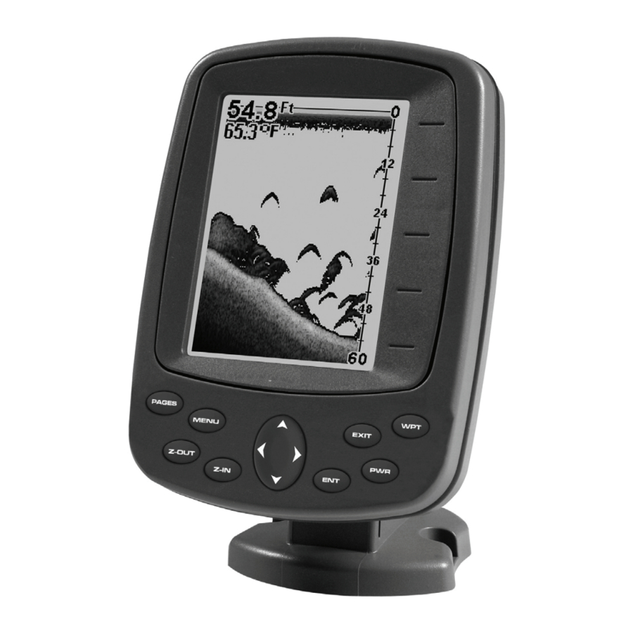
Basic Sonar Operation Keyboard Numbers in the photo correspond to key explanations below. 1. PWR/LIGHT – The the backlight. Depress the 2. PAGES – Pressing this and the arrow keys (4) switches the unit be- tween the different page display screens. 3. -
Page 30: Main Menu
5. ENT – This key allows you to save data, accept values or execute menu commands. It is also used to create event marker icons. 6. EXIT – The Exit key lets you return to the previous screen, clear data or close a menu. 7. -
Page 31: Sonar Menu
• Sun/Moon Calculations: displays the rising and setting time of the sun and moon. • Timers: gives you access to the Up Timer, Down Timer and Clock Alarm Dialogs. Sonar Menu Access the Sonar Menu by pressing the key one time. Select a MENU menu item by using ↑... -
Page 32: Basic Sonar Quick Reference
Basic Sonar Quick Reference 1. Mount the transducer and unit. Connect the unit to electric power and the transducer. 2. Launch your boat. 3. To turn on the unit, press and release 4. Head for your fishing grounds. Your unit automatically displays digi- tal depth and surface water temperature in the corner of the screen. - Page 33 Digital data overlay (depth & temperature) Fish arches around school of bait fish Structure Sonar Page, showing full sonar chart mode. Pages The M52 Pro has five major Sonar display op- tions. They are the Full Sonar Chart, Split Zoom Sonar Chart, Digital Data, Flasher and Pro Tips.
-
Page 34: Sonar Operations
Full sonar chart (left) and Split Zoom Chart (right). Digital Data page (left) with Flasher page (center) and Pro Tips page (right). Sonar Operations Sensitivity controls the unit's ability to pick up echoes. If you want to see more detail, try increasing the sensitivity. There are situations when too much clutter appears on the screen. - Page 35 These figures show results of different sensitivity levels on the same location. Sensitivity set at 50 percent (left). Sensitivity set at 100 percent (center). Sensitivity Control bar (right). To adjust sensitivity: 1. Press MENU 2. The Sensitivity Control Bar appears. Press ↓ to decrease sensitivity; press ↑...
- Page 36 Fish I.D. is an easier way for a sonar novice to recognize a fish signal return when he sees it. However, locating fish by symbol only has some limitations. Your sonar unit's microprocessor is remarkably powerful, but it can be fooled.
-
Page 37: Section 4: Sonar Options & Other Features
Section 4: Sonar Options & Other Features ASP™ (Advanced Signal Processing) The ASP™ feature is a noise rejection system built into the sonar unit that constantly evaluates the effects of boat speed, water conditions and interference. This automatic feature gives you the best display pos- sible under most conditions. -
Page 38: Zone Alarm
At left, Main Menu and Sonar Alarms command. To adjust and turn on the shallow alarm: 1. Press MENU MENU 2. Press ↓ to HALLOW 3. Press ↑ or ↓ until the depth is correct, then press 4. Press ↑ to HALLOW 5. -
Page 39: Fish Alarm
At left, Sonar Alarms menu, with Adjust Zone command selected. At right, Adjust Zone Alarm selection box, with Upper Limit selected. 3. To set the upper boundary for the Zone Alarm, use ← or→ to select . Press ↑ or ↓ to move the top of the bar to the desired depth. PPER 4. -
Page 40: Chart Speed
To turn on fish alarm: 1. Press MENU MENU 2. Press ↓ to LARM 3. To turn off the alarm, press EXIT LARM Chart Speed Chart Speed allows you to control the rate echoes scroll across the screen. At left, Sonar Page menu. At right, Chart Speed Control Bar. To change chart speed: 1. -
Page 41: Depth Range - Automatic
Cursor line Depth box At left, Depth Cursor selected. At right, sonar chart with the depth cursor active. The line indicates the large fish is 40.53 feet deep. Depth Range - Automatic When turned on for the first time, the bottom signal is automatically placed in the lower half of the screen. -
Page 42: Depth Range - Upper And Lower Limits
To switch to Manual Depth Range: 1. First, turn off automatic depth range. From the Sonar Page, press |↓ to MENU EPTH 2. Press ↑ to EPTH 3. Press ↓ or ↑ to select a different depth range. A horizontal dark bar highlights the selected range. -
Page 43: Fastrack
To change the upper and lower limits: 1. From the Sonar Page, press The Sonar Chart Limits menu appears, with Upper Limit selected. 2. To set the upper limit, press correct, then → to move to the second digit. Repeat until the depth is correct, then press 3. -
Page 44: Fishtrack
Sonar Features menu with Fish I.D. Symbols selected. When the check box to the left is checked, the feature is on. FishTrack™ FishTrack shows the depth of a fish symbol when it appears on the dis- play. This feature is available only when the Fish I.D. is turned on. To turn on FishTrack and Fish ID: 1. -
Page 45: Overlay Data
At left, Sonar Page menu with GrayLine command selected. At right, the GrayLine control bar. To adjust the Grayline level: 1. From the Sonar Page, press 2. The Grayline Control Bar appears. Press ↓ to decrease Grayline; press ↑ to increase Grayline. 3. -
Page 46: Ping Speed & Hyperscroll
To turn off overlay data: 1. Press |↓ to MENU 2. Press ↓ or ↑ to select Data Type, then press to the left of the selected data type disappears. 3. To return to the previous page, press EXIT EXIT To change overlay data font size: 1. -
Page 47: Reset Options
To adjust Sensitivity: 1. From the Sonar Page, press 2. The Sensitivity Control Bar appears. Press ↓ to decrease sensitivity; press ↑ to increase sensitivity. When it's set at the desired level, press . (When you reach the maximum or minimum limit, a tone sounds.) EXIT To turn off HyperScroll: 1. -
Page 48: Keel And Waterline Offset
To adjust sensitivity in auto mode: 1. From the Sonar Page, press |↓ to MENU ENSITIVITY 2. Highlight and press ENSITIVITY 2. The Sensitivity Control Bar appears. Press ↓ to decrease sensitivity; press ↑ to increase sensitivity. When it's set at the desired level, press EXIT At left, Sonar Menu with Sensitivity command selected. -
Page 49: Sonar Color Mode
To set Keel Offset: 1. Press MENU MENU 2. The Keel Offset dialog box appears. Press ↓ to so that the displayed number shows a minus (–) sign instead of the plus (+) sign. 3. Press ↓ until the number shows – 3.5, then press indicators now accurately show the depth of water beneath the keel. -
Page 50: Split Zoom Sonar Chart
screen aid in determining the depth of targets. The line at the top of the screen represents the surface. The bottom depth and surface tem- perature (if the unit is equipped with a temperature sensor or a trans- ducer with a temp sensor built in) show at the top left corner of the screen. -
Page 51: Flasher
Flasher The Flasher page represents a flasher-style sonar. A circular dial shows all returning echoes at a high screen refresh rate. It uses the Grayline feature to show weaker targets as lighter colors. The bottom depth is also shown as a black bar across the outer circle. Pro Tips page (left). -
Page 52: Stop Chart
Stop Chart The Stop Chart feature allow you to stop the sonar chart from scrolling. To stop/start chart: 1. Press |↓ to MENU the sonar chart. Surface Clarity Surface Clarity control reduces or eliminates surface clutter signals from the display. To adjust the Surface Clarity level: 1. -
Page 53: Section 5: Sonar Troubleshooting
Section 5: Sonar Troubleshooting Unit won't turn on: 1. Check the power cable's connection at the unit. Check the fuse. Also check the wiring. 2. Make certain the power cable is wired properly. The red wire con- nects to the positive battery terminal, black to negative or ground. 3. - Page 54 bubbles in the water disrupt the sonar signals, interfering with its ability to find the bottom or other targets. The technical term for this is cavita- tion. 2. Electrical noise from the boat's motor can interfere with the sonar. Try using resistor spark plugs or routing the sonar unit's power and transducer cables away from other electrical wiring on the boat.
-
Page 55: Section 6: Basic Gps Operations
Section 6: Basic GPS Operations Main Menu You can access the Main Menu from any of the four Page screens by pressing . To clear the menu screen and return to the page MENU MENU display, press EXIT Main Menu. The Main Menu commands and their functions are: Screen: changes the contrast or brightness of the display screen. -
Page 56: Sonar Pages
Trip Calculator: shows trip status and statistics. Timers: controls the up timer, down timer and alarm clock settings. Browse MMC Files: this allows you to view the installed MMC card and the files it contains. Pages The unit has four GPS Page displays that represent the four major oper- ating modes. -
Page 57: Navigation Page
Satellite Page. Left view indicates unit has not locked on to any satel- lites and does not have a fix on its position. Center view shows satel- lites being scanned. Right view shows satellite lock-on with a 3D posi- tion acquired (latitude, longitude and altitude.) This screen shows a graphical view of the satellites that are in view. - Page 58 Track or compass heading indicator, showing direction of travel Trail line Navigation information displays Navigation Page, recording a trail, traveling east. Page looks like this when the unit is not navigating to a waypoint , following When navigating to a waypoint, the Navigation screen looks like the following figure.
-
Page 59: Position Page
white corridor represent lines that show the current cross track error range. The default for the cross track error range is 0.20 miles. In the example above, the driver is headed north (a 12º track) toward a waypoint 12º (bearing) away. The cross track error range (white corri- dor) is 0.20 miles either side of the course. - Page 60 The plotter's zoom range is the distance across the screen. This number shows in the lower right corner of the screen. In the first example fig- ure below, the range is 4,000 miles from the left edge of the display to the right edge.
-
Page 61: Selecting Any Plotter Item With The Cursor
Selecting Any Plotter Item With the Cursor 1. Use the zoom keys and the arrow keys to move around the plotter and find the item you wish to select. 2. Use the arrow keys and center the cursor cross-hair on the desired ob- ject. -
Page 62: Gps Quick Reference
Start outdoors, with a clear view of the open sky. As you practice, try navi- gating to a location at least a few blocks away. While you're learning, navigation in too small an area will constantly trigger arrival alarms. 1. Connect the unit to electric power and the antenna module. Make sure the MMC is in. -
Page 63: Cancel Navigation
Find Distance between Points 1. While on the Plotter Page press: 2. Center your cursor over the position you want to find the distance to. A rubber band line appears, connecting your current position to the cursor's location. The distance along that line will appear in the infor- mation box at the bottom of the screen. - Page 64 Create Waypoint at Current Position While you are traveling, press automatically given a name with a sequential number, such as "way- point 003." The waypoint symbol and number appear on the plotter. Sequence for setting a waypoint. Step 1: while traveling, quickly press WPT twice to call up Find Waypoint screen (shown at left) and set a point.
-
Page 65: Delete A Waypoint
Create Waypoint by Average Position This feature sets a waypoint at the current position after averaging several position readings. 1. Press |↓ to 2. Press ↓ or ↑ to VERAGE 3. Wait while the unit takes points to average for the position. (The greater the number of points, the greater the accuracy.) When the desired number of points accumulates, press 4. -
Page 66: Find A Waypoint
To delete all waypoints at one time: 1. Press MENU MENU |← to POINTS 2. To return to the previous page, press Edit a Waypoint Edit Waypoint Name 1. Press |↓ to waypoint name| 2. Press ↑ or ↓ to change the first character, then press → to the next character and repeat until the name is correct. -
Page 67: Navigate To A Waypoint
3. If the list is short, you can jump directly to the . Use ↑ or ↓ to select the waypoint name, press pressing the waypoint information screen appears with the lected. Waypoint information screen on waypoint 004. Screen shows name, lati- tude/longitude, distance to waypoint and its compass bearing. -
Page 68: Set Man Overboard (Mob) Waypoint
2. If your waypoint list is a long one, you can spell out the waypoint name in the first character, then press → to move the cursor to the next character and repeat until the name is correct, then press below.) 3. -
Page 69: Navigate Back To Mob Waypoint
Navigate Back to MOB Waypoint Find your way back to the accident position with the Navigation Page or Plotter Page. When MOB is activated, the Navigation Page auto- matically shows the compass rose with its bearing arrow pointing to- ward the man overboard position. Navigating to Man Overboard: Navigation Page, left and center, and Plotter Page, right. - Page 70 Sequence for saving a trail and beginning a new one. At left, My Trails command. Center, the Trails Menu. The arrow to the right of Trail 3 indicates the trail is "active," and the check to the left indicates the trail is visible on the plotter display.
-
Page 71: Delete A Trail
Delete a Trail This is the command used to erase or delete a trail. 1. Press MENU MENU 2. Press → ELETE Tip: You can also delete all trails at once. 1. Press MENU 2. Press → to Display a Saved Trail The active trail is automatically visible on the plotter display with the factory default settings. -
Page 72: Navigate A Trail
At left, trail selected with plotter cursor. The info box at the bottom of the screen shows distance and bearing from current position to the selected point on the trail. At right, the Edit Trail menu. Navigate a Trail There are three methods for following a trail: visual trailing, navigat- ing a trail (forward) and backtracking a trail (backward). - Page 73 NOTE: If you are already located at or near the beginning of your trail, the arrival alarm will go off as soon as you press Enter. Just press to clear the alarm and proceed. 5. When you reach your destination, cancel navigation. Figure 1 Figure 3 Navigate a trail menu sequence: Fig.
-
Page 74: Navigate A Back Trail
Trail point Present position arrow Navigate trail, plotter views: at left boater is heading straight toward trail point 3. Center, when the point is reached, Arrival Alarm goes off and the steering arrow points toward next trail point. At right, boater has reached point 3 and has turned northeast to follow trail to point 4. -
Page 75: Icons
Icons Icons are graphic symbols used to mark some location, personal point of interest or event. They can be placed on the plotter screen, saved and 3. Select the desired symbol for the icon and press pears on the plotter. Create Icon at Current Position 1. -
Page 76: Routes
3. The Delete All Icons command will ask if you are sure. Press ← to . All icons will be deleted from the plotter. To Delete By Symbol: 1. Press |↓ to MENU 2. Press ↓ to ELETE 3. The Delete by Symbol command will launch the Select Symbol menu. Select the icon symbol to delete and press ing all icons with the selected symbol have been deleted. - Page 77 Route Planning command on Main Menu, left, will open the Route List screen, right. 1. From the AVIGATION press |↓ to MENU MENU 2. Press ↓|↑ or ↓ to route name| . The Plotter Page appears with the cursor showing. LOTTER Edit Route menu, left.
-
Page 78: Delete A Route
Route creation sequence: At left, the Plotter Page shows the waypoints we want to visit in our route. Set the first route point at waypoint (001). Center, move cursor to the next waypoint in the route and press Enter. Waypoint added message appears. Right, continue adding way- points until you reach the end of the route. - Page 79 3. Press ↑ or ↓ to change the first character, then press → to move the cursor to the next character and repeat until the name is correct, then press . Return to the main display by pressing You also can edit the route by adding and removing waypoints.
- Page 80 Navigate a Route backward Here's how you run a route backward, from the end waypoint to the beginning waypoint: 1. From the AVIGATION press |↓ to MENU MENU 2. Press ↓ to select route name| |← to VERSE AVIGATE 3. Upon arrival at your destination, cancel navigation: press |↓...
-
Page 81: Utilities
Utilities Utilities are useful tools for traveling or for outdoor activities. Alarm Clock To get to the alarm clock menu: press LARM LOCK Sun/Moon Rise & Set Calculator To get to the Sun/Moon menu: press LATIONS Trip Calculator To get to the Calculator menu: press Trip Down Timer To get to the Down Timer menu: press IMER... - Page 82 Notes...
-
Page 83: Section 7: System & Gps Setup Options
Section 7: System & GPS Setup Options Alarms You unit has three alarms: Arrival Alarm, Off Course Alarm and An- chor Alarm. You can turn the alarms off and on and change their dis- tance settings. You can set an arrival alarm to flash a warning message and sound a tone when you cross a preset distance from a waypoint. -
Page 84: Auto Satellite Search
4. When your adjustments are finished, return to the last page dis- played by repeatedly pressing IMPORTANT ALARM NOTES: Anchor Alarm — The anchor alarm may be triggered even when you are sitting still. Typically, this happens when using small (less than 0.05 mile) anchor alarm ranges. -
Page 85: Coordinate System Selection
Coordinate System Selection The Coordinate System Menu lets you select the coordinate system to use when displaying and entering position coordinates. Menus for changing coordinate system used to display positions. To get to Coordinate System Selection: 1. Press MENU MENU 2. -
Page 86: Map Fix
Map Fix Map Fix is used with charts or maps. This system asks for a reference position in latitude/longitude, which you take from a marked location on the map. It then shows the present position as distance on the map from that reference point. -
Page 87: Customize Page Displays
Customize Page Displays The Plotter, Position and Navigation pages all have customizable op- tions. These options control which information is displayed on each page. Customize Position Page 1. While on the GPS Position Page, press The display box in the top left corner begins flashing. 2. -
Page 88: Hide Gps Features
Input the desired settings, then turn on the simulator by highlighting GPS S IMULATOR close this menu. A message and tone appear periodically, warning you that the simulator is on. To turn the simulator off, repeat the above steps or turn the unit off. Hide GPS Features If there is no GPS antenna/receiver module attached to this unit, the GPS menus and features can be hidden from view with this command. -
Page 89: Plotter Orientation
Plotter Orientation By default, this receiver shows the plotter with north always at the top of the screen. This is the way most maps and charts are printed on paper. To switch to a different orientation, a track-up mode rotates the plotter display as you turn. - Page 90 Overlay Data command on the Sonar Menu, at left. Overlay Data Shown selection menu, right. In this example, we scrolled down the data list to highlight "Ground Speed." When selected, the data type shifts to the top of the data list and a check mark appears beside the data type.
-
Page 91: Pop-Up Help
Tip: If you wish, you can change the displayed data font size when you select a data type: 1. From the Plotter or Sonar page, press |↓ to MENU VERLAY 2. Press ↓ or ↑ to select Data Type|press → or ←... -
Page 92: Reset Options
The Position Pinning feature was developed so that when you stopped, the unit locked the present position on the GPS plotter until you moved a short distance or exceeded a very slow speed. To turn on Position Pinning: 1. Press MENU MENU 2. -
Page 93: Set Language
Set Language This unit's menus are available in 10 languages: English, French, Ger- man, Spanish, Italian, Danish, Swedish, Russian, Dutch and Finnish. To select a different language: 1. Press MENU MENU 2. Press ↓ to ANGUAGE 3. Use ↓ or ↑ to select a different language and press now appear in the language you selected. -
Page 94: Software Version Information
To show WAAS Alarm: 1. Press MENU MENU 2. With the option highlighted, press check it (turn on). After the option is set, press the page display. 3. You can return to this command and press ture on. Software Version Information You can find out what software version is running in your sonar unit by using the Software Information command. -
Page 95: Track Smoothing
To set Alarm Volume: The left end of the scale is low volume; the right end is high volume. Af- ter the option is set, press Press ↓ to To set Alarm Style: style, then press ENT. to the page display. Track Smoothing Track Smoothing prevents wandering of trails, the steering arrow, compass rose and plotter display in... - Page 96 traveling in a straight line. Once you deviate from a straight line, the unit "drops" a plot point (trail waypoint) onto the trail. This conserves plot trail points. If a plot trail uses all of the available points allotted to it, the beginning points are taken away and placed at the end of the trail.
-
Page 97: Units Of Measure
Trail Options menu: Update Time Rate setting, left, and Update Dis- Specific Trail Options Delete Trail To delete a specific trail: From the Trails Menu, press ↓ to Trail Name| . The Edit Trail menu appears as seen in the following fig- ure. - Page 98 Main Menu, left, Units of Measure Menu, right. To change unit of measure: 1. Press |↓ to |↓ to MENU MENU YSTEM ETUP NITS OF EASURE 2. Press ↓ to the desired units and then press After all the options ENT.
-
Page 99: Index
Accessories, 7, 21, 22 Accessory, 19, 20, 51 Alarm Clock, 79 Alarms, 28, 35, 36, 37, 38, 53, 60, Anchor Alarm, 81, 82 Antenna, 6, 51, 60, 86 Arrival Alarm, 60, 71, 78, 81, 82 ASP™ 17, 35 Backlights / Lighting, 5 Batteries, 7, 19, 20, 24, 25, 51 Brightness, 28, 53, 90 Cancel Navigation, 53, 60, 61, 77,... - Page 100 60, 61, 65, 66, 67, 70, 71, 74, 75, 76, 77, 78, 86, 87 Position, 54, 57, 60, 85 Satellite Status, 54, 55, 60 Pages, 31, 47, 54, 60, 87 Navigation Page, 54, 55, 56, 57, 59, 60, 66, 67, 71, 74, 75, 76, 77, 78, 85 Plotter Page, 6, 28, 54, 56, 57, 58, 59, 60, 61, 65, 66, 67, 70, 71,...
- Page 101 Notes...
- Page 102 Notes...
- Page 103 NAVICO DATABASES LICENSE AGREEMENT THIS IS A LEGAL AGREEMENT BETWEEN THE END-USER WHO FIRST PURCHASES THIS PRODUCT AS A CONSUMER ITEM FOR PERSONAL, FAMILY, OR HOUSEHOLD USE ("YOU") AND LOWRANCE ELECTRONICS, INC., THE MANUFACTURER OF THIS PRODUCT ("WE", "OUR", OR "US"). USING THE PRODUCT ACCOMPANIED BY THIS LICENSE AGREEMENT CONSTITUTES ACCEPTANCE OF THESE TERMS AND CONDITIONS.
-
Page 104: Databases Limited Warranty
DATABASES LIMITED WARRANTY "We", "our", or "us" refers to Navico, Inc., the manufacturer of this product. "You" or "your" refers to the first person who purchases the product as a con- sumer item for personal, family, or household use. The Databases Limited War- ranty applies to the one or more databases that your product may contain. - Page 105 NAVICO FULL ONE-YEAR WARRANTY "We," "our," or "us" refers to NAVICO, INC., the manufacturer of this product. "You" or "your" refers to the first person who purchases this product as a consumer item for per- sonal, family or household use. We warrant this product against defects or malfunctions in materials and workmanship, and against failure to conform to this product's written specifications, all for one (1) year from the date of original purchase by you.
-
Page 106: How To Obtain Service
How to Obtain Service… …in the USA: We back your investment in quality products with quick, expert service and genuine Lowrance parts. If you're in the United States and you have technical, return or repair questions, please contact the Factory Customer Service Department. -
Page 107: Accessory Ordering Information
Accessory Ordering Information for all countries To order Lowrance accessories such as power cables or transducers, please contact: 1) Your local marine dealer or consumer electronics store. Most quality dealers that handle marine electronic equipment or other consumer electronics should be able to assist you with these items. To locate a Lowrance dealer near you, visit our web site, www.lowrance.com and look for the Dealer Locator. - Page 108 Visit our web site: Lowrance Pub. 988-0152-28A © Copyright 2008 All Rights Reserved Printed in USA 042908 Navico...