Sony VPL-ES1 Service Manual
Data projector
Hide thumbs
Also See for VPL-ES1:
- Operating instructions manual (156 pages) ,
- Brochure & specs (6 pages) ,
- Specifications (2 pages)
Table of Contents
Advertisement
Advertisement
Table of Contents

Related Manuals for Sony VPL-ES1


Summary of Contents for Sony VPL-ES1
- Page 1 DATA PROJECTOR VPL-ES1 REMOTE COMMANDER RM-PJ2 SERVICE MANUAL 1st Edition...
- Page 2 LES SCHÉMAS DE PRINCIPE, LES VUES EXPLOSÉES ET LES CRITICAL TO SAFE OPERATION. REPLACE THESE COMPO- LISTES DE PIECES SONT D’UNE IMPORTANCE CRITIQUE NENTS WITH SONY PARTS WHOSE PART NUMBERS APPEAR POUR LA SÉCURITÉ DU FONCTIONNEMENT. NE LES AS SHOWN IN THIS MANUAL OR IN SUPPLEMENTS PUB- REMPLACER QUE PAR DES COMPOSANTS SONY DONT LE LISHED BY SONY.
- Page 3 Kommunen. Entladen sind Batterien in der Regel dann, wenn das Gerät abschaltet und signalisiert “Batterie leer” oder nach längerer Gebrauchsdauer der Batterien “nicht mehr einwandfrei funktioniert”. Um sicherzugehen, kleben Sie die Batteriepole z.B. mit einem Klebestreifen ab oder geben Sie die Batterien einzeln in einen Plastikbeutel. VPL-ES1...
-
Page 4: Table Of Contents
White Balance Adjustment ................. 2-9 2-5-1. HIGH Mode of INPUT-A ............2-9 2-5-2. LOW Mode of INPUT-A ............2-9 2-5-3. HIGH Mode of VIDEO .............. 2-9 2-5-4. LOW Mode of VIDEO ............... 2-9 2-6. Memory Structure ..................2-10 3. Semiconductors ................. VPL-ES1... - Page 5 H ......................6-18 L ......................6-19 NR ......................6-19 G (1/2) ..................... 6-21 G (2/2) ..................... 6-22 Board Layouts Q ........................ 6-3 C ........................ 6-4 V ......................6-14 H ......................6-18 L ......................6-19 NR ......................6-19 G ......................6-20 VPL-ES1...
-
Page 6: Service Overview
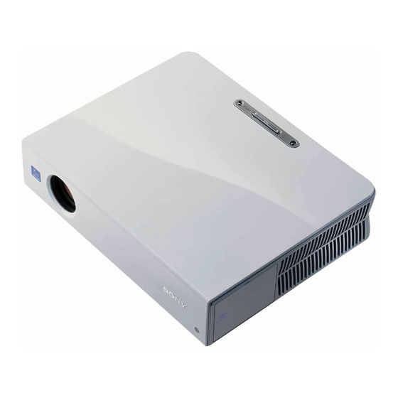
Section 1 Service Overview 1-1. Appearance Figure VPL-ES1 RM-PJ2 1-2. Board Locations Lamp power supply VPL-ES1... -
Page 7: Disassembly
(+BV 3 x 70) 1-3-2. H Board . Remove the top panel assembly. (Refer to 1-3-1.) 3 Top panel 1 Five claws 7 Button (H) 8 H board 4 Flat connector assembly CN10 6 Holder (H) 2 Two dowels 5 Two claws VPL-ES1... -
Page 8: C Board
8 Two screws Side panel shaft 7 Screw 9 Bracket (C) (+B 3 x 6) C board 0 Fuse connector assembly CN806 CN811 !- C board CN905 CN809 6 Remove the C board in the direction of the arrow C. VPL-ES1... -
Page 9: Lens Gear
3 Remove the four claws 4 Dowel in the direction of the arrow B. Side panel assembly Fan holder 2 Remove the side panel assembly in the direction of the arrow A. VPL-ES1... -
Page 10: Fan (60Mm) And D.c. Fan (70Mm)
1-3-7. Lamp House . Remove the fan holder. (Refer to 1-3-5.) 4 Screw 2 Two screws (+BTP 3 x 10) (+BTP 3 x 10) 1 Remove the harneses 3 Lamp power supply 5 Lamp house CN807 CN810 C board VPL-ES1... -
Page 11: Optics Block Assembly
1 Two precision screws (+B 2 x 5) 6 Pre radiation polarizer (G) assembly 5 Radiation polarizer (R) assembly 7 Radiation polarizer (G) assembly 9 Radiation polarizer 2 Prism block assembly (B) assembly 8 Pre radiation polarizer (B) assembly VPL-ES1... -
Page 12: Incidence Polarizer (R), (G), (B)
. Remove the optics unit assembly. (Refer to 1-3-8.) . Remove the prism block assembly. (Refer to 1-3-9.) 1 Six screws (+BTP 3 x 10) 2 Unit cover 3 Incidence polarizer (R) assembly 4 Incidence polarizer (G) assembly 5 Incidence polarizer (B) assembly VPL-ES1... -
Page 13: Side Panel Assembly-1
C board 3 Open the side panel assembly in the direction of the arrow A. Cover (G) 5 Screw (+B 3 x 6) Cover (B2) 6 Cover (G), Sheet (G) Cover (B) G board Sheet (G) G board C board VPL-ES1... -
Page 14: Side Panel Assembly-2
1 Open the side panel assembly in the direction of the arrow AB . 3 Sheet (NR) 4 NR board CN01 5 L board CN70 Claw Two claws 7 Sheet (speaker) 8 Speaker assembly 9 Side panel assembly 6 Speaker bracket VPL-ES1... -
Page 15: G Board
. Remove the cover (G), sheet (G). (Refer to 1-3-11) . Remove the G board. (Refer to 1-3-13.) 3 Sheet (B) 2 Two screws (+B 3 x 6) 1 Two screws (+BTP 3 x 10) 4 Lamp power supply C board 1-10 VPL-ES1... -
Page 16: Fan (Sirocco/For Lamp)
1 Two screws (+BTP 3 x10) 5 Remove the D.C. fan (Sirocco/For lamp) in the direction of the arrow. 4 Loosen the screw. 2 Fan bracket 6 D.C. fan (Sirocco/For lamp) Fan holder C board 3 Two dowels 1-11 VPL-ES1... -
Page 17: Fan (Sirocco)
(+BTP 3 x 10) CN802 CN806 CN811 CN809 CN905 4 Fan holder C board 3 Remove the fan holder in the direction of the arrow. Dowel 7 D.C. fan (Sirocco) 6 Two dowels 5 Remove the harneses D.C. fan (Sirocco) 1-12 VPL-ES1... -
Page 18: Adjuster Block Assembly
4 Optics block assembly • Remove the optics block assembly. (Refer to 1-3-8.) 5 Three screws (+BTP 3 x 10) 9 Adjuster block assembly 7 Dowel 6 Dowel 8 Remove the adjuster block assembly in the direction of the arrow. 1-13 VPL-ES1... -
Page 19: Warning On Power Connection
Cord type H05VV-F H05VV-F N13237/CO-228 VCTF Rated Voltage & Current 10A/125V 10A/125V 10A/250V 10A/250V 10A/250V 7A/125V Safety approval UL/CSA UL/CSA DENAN Cord length (max.) 4.5m – (1) Use an appropriate rating plug which is applied to local regulations. 1-14 VPL-ES1... -
Page 20: Electrical Adjustments
2. Align the marking position of the lens zoom gear with 9. Install the VPL-ES1 in the cabinet. Confirm that the the protrusion of the lens gear approximately by visual illumination range error is within the allowable range observation as shown below. -
Page 21: How To Enter The Factory Mode
ZOOM and FOCUS are moved to their the FLAT FIELD 100 IRE signal to the input connec- very ends. tor. Leave the VPL-ES1 with POWER ON for 10 minutes or longer for aging. 2. Enter the Factory Mode. Enter the Device Adjust... -
Page 27: Service Know-How
8. Enter the Other MENU and let the message “38 Other/ X TILT xxxx” (xxxx is any value) on screen. 9. Enter the X TILT value while the VPL-ES1 is set in the horizontal position, in “35 Other/TILT CO”. 10. Turn the VPL-ES1 so that it faces upward in the vertical position. -
Page 28: White Balance Adjustment
INPUT-A LOW mode, adjust the BIAS R and BIAS B for the same value as those of the INPUT-A HIGH 1. Input the 80 IRE flat field signal to the INPUT-A mode. connector. 4. Press the MEMORY key and save the adjustment value. VPL-ES1... -
Page 29: Memory Structure
S Video Memory Memory Input-A Input-A Image Flip Image Flip Up/Down inversionis Up/Down inversionis Image Flip Memory impossible impossible Memory Memory Up/Down inversionis Up/Down inversionis possible possible CPU ROM External NVM CPU RAM Initialize Memory Active memory copy 2-10 VPL-ES1... - Page 30 The adjustment items(W/B, Device Adjust) that can be adjusted in the Service Mode or in the Special Service Mode, are memorized in the NVM at the time when the user performs adjustment and performs the memory operation. Note that the factory adjustment data will be lost at this moment. 2-11 VPL-ES1...
-
Page 31: Semiconductors
TC74VHCT540AFT(EL) TC74HC4052AFT(EL) TDA7309D013TR TPA2001D1PWR TK11900MTL TOP VIEW TOP VIEW 20pin SOP 16pin SOP AIC1117A-18PYJTR AIC1117A-33PYJTR CXA2171AQ AIC1117A-50PYJTR MAX4382EUD+TG069 CXA2171AQ-T6 6pin CHIP SN74LV00APWR CXA7005R-T4 SN74LV02APWR TL431CPK-E2 TC74LCX125FT(EL) TOP VIEW 8pin DIP TOP VIEW 48pin QFP TOP VIEW S-80928CNMC-G8YT2G 14pin SOP VPL-ES1... - Page 32 ANODE CATHODE CATHODE ANODE HN1D03FU-TE85L CATHODE HN1D03FU-TE85R GATE DRAIN SOURCE 1SS355TE-17 ANODE EC31QS03L-TE12L DTC114EU MA111-(K8).S0 SEC1801C DTC114EUA-T106 MA111-TX SEC1901C RD30SB-T1 SEC2422C RD39SB-T1 RD9.1SB2 CATHOD E MARK RD9.1SB2-T1 MA3J14700LSO HN1B01FU-TE85R HN1C01FU-TE85R ANODE CATHODE D10SC4M D10SC6M CATHODE ANODE D10SC6M(RECTI) NNCD5.6LG-T1 SI4425DY-T1 VPL-ES1...
-
Page 33: Spare Parts
Ne les remplacer que par une pièce portant le numéro spécifié. 2. Standardization of Parts Some repair parts supplied by Sony differ from those used for the unit. These are because of parts common- ality and improvement. Parts List has the present standardized repair parts. -
Page 34: Exploded Views
SP Description A-1302-422-A s MOUNTED CIRCUIT BOARD, C A-1302-423-A s MOUNTED CIRCUIT BOARD, G A-1405-830-A s MOUNTED CIRCUIT BOARD, H A-1603-156-A s SPEAKER ASSY +B 3x6 4-099-089-01 o EMBLEM (E1) 4-099-113-01 s FILTER (E1) Screws/Washers 7-682-547-04 s SCREW +B 3X6 VPL-ES1... - Page 35 1-787-065-21 s D.C. FAN (SIROCCO) 1-787-078-11 s DC FAN (60mm) 1-787-079-11 s D.C. FAN (SIROCCO) (For Lamp) 1-787-080-11 s DC FAN (70mm) 1-468-803-11 s LAMP POWER SUPPLY 4-099-158-01 s HOUS, LAMP Screws/Washers 7-685-547-19 s SCREW +BTP 3X10 (EP-FE/ZNBK/CM2) 7-682-547-04 s SCREW +B 3X6 VPL-ES1...
- Page 36 1-818-098-11 s INLET, AC (WITH NISE FILTER) 3-701-822-01 s HOLDER, WIRE 4-084-604-11 s FOOT, REAR 4-096-049-01 s FOOT, FRONT Screws/Washers 7-682-247-09 s SCREW +K 3X6 7-682-547-04 s SCREW +B 3X6 7-685-547-19 s SCREW +BTP 3X10 (EP-FE/ZNBK/CM2) 7-682-961-01 s SCREW +PSW 4X8 VPL-ES1...
- Page 37 A-1606-256-A s RADIATION POLARIZER (G) ASSY 7-621-771-06 s SCREW +B 2X5 A-1606-257-A s RADIATION POLARIZER (B) ASSY 7-685-105-11 s SCREW +PTP 2X8 (EP-FE/ZNBK/CM2) 7-685-647-79 s SCREW +BVTP 3X10 (EP-FE/ZNBK/CM2) A-1606-248-A s PROJECTION LENS ASSY 7-682-649-09 s SCREW +PS 3X10 (EP-FE/ZNBK/CM2) VPL-ES1...
-
Page 38: Electrical Parts List
C156 1-126-205-11 s CAPACITOR,ELECT 47M/6.3 C331 1-125-777-11 s CAPACITOR CERAMIC 0.1MF/10V C332 1-125-777-11 s CAPACITOR CERAMIC 0.1MF/10V C157 1-126-205-11 s CAPACITOR,ELECT 47M/6.3 C337 1-119-667-11 s CAPACITOR CERAMIC 22MF/10V(F) C158 1-126-205-11 s CAPACITOR,ELECT 47M/6.3 C339 1-164-852-11 s CAPACITOR,CHIP CERAMIC 12PF/16 VPL-ES1... - Page 39 1-125-777-11 s CAPACITOR CERAMIC 0.1MF/10V C661 1-128-992-11 s CAPACITOR ELECT 47MF 25V C429 1-164-943-11 s CAPACITOR,CHIP CERAMIC 0.01MF C662 1-131-992-11 s CAP, CERAMIC 100000PF F 1608 C430 1-125-777-11 s CAPACITOR CERAMIC 0.1MF/10V C663 1-131-992-11 s CAP, CERAMIC 100000PF F 1608 VPL-ES1...
- Page 40 1-770-626-21 s PIN, CONNECTOR (L TYPE) 9P C906 1-125-777-11 s CAPACITOR CERAMIC 0.1MF/10V CN905 1-770-622-21 s PIN, CONNECTOR 5P C907 1-125-777-11 s CAPACITOR CERAMIC 0.1MF/10V C911 1-128-992-11 s CAPACITOR ELECT 47MF 25V CN906 1-580-055-21 o PIN, CONNECTOR 2P C912 1-117-370-11 s CAPACITOR CERAMIC 10MF (3216) VPL-ES1...
- Page 41 8-759-643-48 s IC BA00ASFP-E2 FB810 1-500-451-11 s MICRO INDUCTOR (CHIP) 41P750S IC901 8-759-661-55 s IC ST24FC21M6TR FB811 1-500-451-11 s MICRO INDUCTOR (CHIP) 41P750S IC902 8-759-833-99 s IC MC74HC4052ADTR2 FB812 1-500-451-11 s MICRO INDUCTOR (CHIP) 41P750S IC903 6-705-510-01 s IC MAX4382EUD+TG069 VPL-ES1...
- Page 42 1-218-953-11 s RESISTOR, CHIP 1K 1/16W Q804 8-729-028-73 s TRANSISTOR DTA114EUA-T106 R213 1-218-953-11 s RESISTOR, CHIP 1K 1/16W Q806 8-729-427-72 s TRANSISTOR XP4501-TXE R214 1-218-953-11 s RESISTOR, CHIP 1K 1/16W Q807 8-729-427-72 s TRANSISTOR XP4501-TXE R216 1-218-990-11 s RESISTOR,CHIP 0 1/16W (1005) 4-10 VPL-ES1...
- Page 43 1-218-957-11 s RESISTOR,CHIP 2.2K 1/16W(1608) R606 1-218-941-81 s C-RES,V 100-1/16W J R345 1-208-643-11 s RESISTOR CHIP 22 1/16W (1005) R607 1-218-957-11 s RESISTOR,CHIP 2.2K 1/16W(1608) R346 1-208-643-11 s RESISTOR CHIP 22 1/16W (1005) R608 1-218-957-11 s RESISTOR,CHIP 2.2K 1/16W(1608) 4-11 VPL-ES1...
- Page 44 1-218-965-11 s RESISTOR, CHIP 10K 1/16W R853 1-218-957-11 s RESISTOR,CHIP 2.2K 1/16W(1608) R757 1-208-683-11 s RESISTOR CHIP 1K 1/16W (1005) R854 1-218-957-11 s RESISTOR,CHIP 2.2K 1/16W(1608) R758 1-208-683-11 s RESISTOR CHIP 1K 1/16W (1005) R901 1-218-969-11 s RESISTOR,CHIP 22K 1/16W (1608) 4-12 VPL-ES1...
- Page 45 (1005) R969 1-208-635-11 s RESISTOR CHIP 10 1/16W (1005) R971 1-218-965-11 s RESISTOR, CHIP 10K 1/16W RB501 1-234-370-11 s RES, NETWORK 22X4 (1005) R972 1-208-635-11 s RESISTOR CHIP 10 1/16W (1005) RB502 1-234-370-11 s RES, NETWORK 22X4 (1005) 4-13 VPL-ES1...
- Page 46 6-500-406-01 s DIODE D10XB80 D102 8-719-304-63 s DIODE RM11C (RECTI) D103 8-719-060-06 s DIODE FSF10A60 D104 8-719-510-11 s DIODE D1FS4 D201 8-719-107-13 s DIODE RD18M-B1 D202 8-719-073-01 s DIODE MA111-(K8).S0 D203 8-719-979-64 s DIODE UF4005PKG23 D204 8-719-055-30 s DIODE D1FS4A-TA 4-14 VPL-ES1...
- Page 47 1-218-907-11 s RESISTOR,CHIP 330K 1/10W(1608) R250 1-216-833-11 s RESISTOR,CHIP 10K 1/10W (1608) R110 1-216-817-11 s RESISTOR,CHIP 470 1/10W 1608 R251 1-218-901-11 s RESISTOR,CHIP 180K 1/10W(1608) R111 1-218-871-11 s RESISTOR,CHIP 10K 1/10W (1608) R252 1-218-883-11 s RESISTOR,CHIP 33K 1/10W (1608) 4-15 VPL-ES1...
- Page 48 1-218-973-11 s RESISTOR,CHIP 47K 1/16W (1005) 1-218-973-11 s RESISTOR,CHIP 47K 1/16W (1005) 1-218-973-11 s RESISTOR,CHIP 47K 1/16W (1005) 1-771-105-11 s SWITCH, TACTILE 1-771-105-11 s SWITCH, TACTILE 1-771-105-11 s SWITCH, TACTILE 1-771-105-11 s SWITCH, TACTILE 1-786-651-11 s TACTILE SWITCH 1-771-105-11 s SWITCH, TACTILE 4-16 VPL-ES1...
- Page 49 1-218-943-11 s RESISTOR,CHIP 150 1/16W 1-218-943-11 s RESISTOR,CHIP 150 1/16W 1-218-943-11 s RESISTOR,CHIP 150 1/16W 1-218-943-11 s RESISTOR,CHIP 150 1/16W 1-218-973-11 s RESISTOR,CHIP 47K 1/16W (1005) 1-218-973-11 s RESISTOR,CHIP 47K 1/16W (1005) 1-218-973-11 s RESISTOR,CHIP 47K 1/16W (1005) 4-17 VPL-ES1...
-
Page 50: Block Diagrams
CN 5P CN FPC12P CN 6P CN 12P CN 2P CN 5P G BOARD SPEAKER ADJUSTOR CPU & PW Write BALLAST H BOARD L BOARD THERM FUSE CN804 CN806 BLOCK ASSY CN806 CN807 CN805 NR BOARD CN702 CN803 CN703 VPL-ES1... -
Page 51: G, H, V, L, Nr
ERROR LED VCC TO C ROGO LAMP CONT CN803 OVP LATCH DC/DC FAN +B OUT DELAY FUNCTION FUNCTION 5V REG SUB 5V OUT LED LOGIC POWER PROT PPROT FROM OTHER SYSTEM CN10 TO C FAN CONT1 CN805 P CONT VPL-ES1... -
Page 52: Diagrams
: NONFLAMMABLE METAL OXIDE : NONFLAMMABLE CEMENT : NONFLAMMABLE WIREWOUND : ADJUSTMENT RESISTOR COIL LF-8L : MICRO INDUCTOR CAPACITOR : TANTALUM : STYROL : POLYPROPYLENE : MYLAR : METALIZED POLYESTER : METALIZED POLYPROPYLENE : BIPOLAR : HIGH TEMPERATURE : HIGH RIPPLE VPL-ES1... -
Page 53: Frame Wiring
CIRC S SUB 5V LAMP TEM P LAMP TEM P GN D CIRC S 1m m LAMP COVER LAMP COVER GN D GN D GN D L CONT CN806 White SPEAKER AWG3 2 1m m 1pin=Red L CONT 2pin=Blk VPL-ES1... -
Page 54: Schematic Diagrams And Board Layouts
1/16W CHIP 1/16W 1/16W CHIP CHIP OUT_G 1/16W CHIP 1/16W C BOARD 1/16W CHIP CHIP (10/10) OUT_B CN904 1/16W 1/16W 1/16W CHIP CHIP CHIP OUT_H OUT_V 1/16W CHIP (VIDEO OUTPUT) B-SS1751-Q -A SIDE- -B SIDE- SUFFIX: -11 SUFFIX: -11 VPL-ES1... - Page 55 JL139 JL914 C906 R143 R920 R312 R912 JL101 JL102 R127 R313 JL911 CN904 CN301 JL126 R958 D916 S101 D915 D914 JL103 JL107 C340 R953 JL912 R141 X301 TP101 R307 C151 JL118 R140 JL901 JL332 C345 -A SIDE- SUFFIX: -11 VPL-ES1...
- Page 56 R 1 5 0 R 1 5 6 R 3 1 5 C 3 4 4 R 1 5 1 R 1 5 7 R 7 0 6 C 7 0 3 T H 7 0 1 -B SIDE- SUFFIX: -11 VPL-ES1...
-
Page 57: C (1/10)
R179 1/16W 1/16W VS S 1/16W R127 CHIP CHIP VSYNC CHIP +1.8V VD D 1/16W R125 CHIP (TO P3,P4) RST_COM R129 (TO P2,P8) C148 C151 C144 CHIP IC103 R126 S-80928CNMC-G8Y-T2 RESET CHIP CLAMP (TO P2) INTERLACE (TO P3,P8) B-SS1751-C-P1 VPL-ES1... -
Page 58: C (2/10)
1/16W CHIP R247 V_DET VS/S_OUT 2.2k D202 1/16W 1SS355 C218 CHIP LIMITER VTIMING VS/S_IN GATESW R216 CHIP C210 C224 C225 C227 R246 R214 C208 1000p R219 0.01 100p 0. 1 1/16W 1/16W CHIP CHIP R218 (2/10) (SYNC SEP) B-SS1751-C-P2 VPL-ES1... -
Page 59: C (3/10)
0. 1 POWER AND GROUND C301 C303 C305 C307 C309 C311 C313 C315 C317 C319 C321 C323 C325 C327 C329 C331 IC301 0. 1 0. 1 0. 1 0. 1 0. 1 PW168A-05V L (3/10) 5/5 SCAN_CONV (SCAN CONV.) B-SS1751-C-P3 VPL-ES1... -
Page 60: C (4/10)
S401 (TO P1,P3) RST_CO M IC406 R407 5.2Vp-p(25kHz) SCL_400K HN58X24256FPIZ EEP_ROM JL430 R404 3.3V-2 LU T 1/16W CHIP CN401 R405 5.2Vp-p(50kHz) 1/16W 3.3V JL401 CHIP W SCL (4/10) JL402 W SDA (3D GAMMA & TG) R406 1/16W CHIP B-SS1751-C-P4 VPL-ES1... -
Page 61: C (5/10)
PDRV_SEN B SENB PDRV_SDA T +13.5V SDAT C517 R517 4.7k 1/16W RN-CP C522 +17V R515 R514 120k (5/10) 1/16W 1/16W R518 C521 C519 3LINESBU S R516 CHIP RN-CP 0. 1 C520 (LCD DRIVE) (TO P6,P7) 1/16W RN-CP B-SS1751-C-P5 6-10 6-10 VPL-ES1... -
Page 62: C (6/10)
PC G JL602 SOUT R604 R601 R603 VVD D 1/16W 1/16W (TO P5,P7) CHIP CHIP 3LINESBUS VCOML (TO P4) GCFB_R GCFB TG_R (TO P4) R612 15.5V 1/16W CHIP (TO P4,P5,P7) C611 C612 0. 1 (6/10) (LCD DRIVE) B-SS9876-C-P6 6-11 6-11 VPL-ES1... -
Page 63: C (7/10)
R651 DW N R653 R654 (TO P4,P5,P6) 1/16W CHIP (TO P5,P6) PC G 3LINESBUS SOUT (TO P4) TG_B VVDD VCOM L (TO P4) GCFB (TO P4,P5,P6) GCFB_B R662 15.5V 1/16W CHIP C662 C661 (7/10) (LCD DRIVE) B-SS1751-C-P7 6-12 6-12 VPL-ES1... -
Page 64: C (8/10)
(TO P10) R707 1/16W CHIP Q701 Q704 SCL_100K_2 (TO P10) SSM6N15FU(TE85R) SSM6N15FU(TE85R) 5V-3 LEVEL_CON V LEVEL_CON V Q706 R779 R778 4.7k DTC114EUA-T106 4.7k INV_SW 1/16W 1/16W CHIP (8/10) CHIP I2C_400K (TO P4) (MAIN CPU) (TO P2) I2C_100K B-SS1751-C-P8 6-13 6-13 VPL-ES1... -
Page 65: C (9/10)
RN-CP TK11125CSCL-G 1/16W 2.5V_REG CHIP FB812 C828 0. 1 TP801 C830 R850 R851 C808 C831 C832 C816 C829 C802 C804 C806 C833 0.01 1/16W 1/16W 6.3V 6.3V 6.3V CHIP CHIP (9/10) (INTERFACE) -B SIDE- SUFFIX: -11 B-SS1751-C-P9 6-14 6-14 VPL-ES1... -
Page 66: C (10/10)
CHIP LOUDR OUTR GNDP GNDN RD9.1SB2-T1 PROTECT C926 0. 1 TP901 DDC_SW 0 REC_OUT_R IN3R C924 0. 1 JL902 D901 Q903 NNCD5.6LG-T1 DTC114EUA-T106 AUDIO PROTECT INV_SW (TO P8) AU_MUT E (10/10) (MONITOR OUT & AUDIO PROCESS) B-SS1751-C-P10 6-15 6-15 VPL-ES1... - Page 67 PGND Driver D/ A 20 19 D_IN 4 SIG_OUT 4 D/ A Driver D_IN 3 SIG_OUT 5 C (2/10) SN74LV244APWR (IC205) D/ A Driver D_IN 2 SIG_OUT 6 D_IN 1 RE F DC_GE N D_IN 0 VCOM_OUT 6-16 6-16 VPL-ES1...
- Page 68 DUTY CYCLE (DAC) FILT 14 13 32 kZ DEMOD Y OUT BIAS Y SENSOR RAMP SELECT A GATE Y FILT DRIVE SELECT B GAIN DEGLITCH ADJUST DEGLITCH GAIN GATE ADJUST DRIVE VDD OK START-UP GAIN PROTECTION THERMAL 6-17 6-17 VPL-ES1...
- Page 69 1/16W CHIP CHIP LEFT DOWN ENTER RIGHT MENU R2 1 2.7k 1.2k 1/16W 1/16W 1/16W 1/16W 1/16W 1/16W CHIP CHIP CHIP CHIP CHIP CHIP (SW,LED) B-SS1751-H CN10 R24R25 JL10 -A SIDE- -B SIDE- SUFFIX: -11 SUFFIX: -11 6-18 6-18 VPL-ES1...
- Page 70 CN803 PIN 1 to 3 IC80 LED_VCC RS-140-T 220k C BOARD(9/10) NSCW215T-T94 SIRCS_RECEVER 1/16W CN803 PIN4, 5 LED_CONT CHIP LOGO_LED B-SS1751-L B-SS1751-NR R80R81 IC80 CN80 -A SIDE- -B SIDE- -A SIDE- -B SIDE- SUFFIX: -11 SUFFIX: -11 SUFFIX: -11 SUFFIX: -11 6-19 6-19 VPL-ES1...
- Page 71 Q206 * J-3 D216 * K-2 Q207 * K-2 D217 Q209 * K-2 D218 * K-3 Q210 * F-1 D219 * J-2 Q211 Q212 * K-2 Q213 * J-2 Q214 Q215 * K-2 -B SIDE- SUFFIX: -11 6-20 6-20 VPL-ES1...
- Page 72 C112 C111 R118 0. 1 0.01 0.22 1/10W 1/10W RN-CP RN-C P C109 1000p (1/2) (AC INLET,PFC CONT) B-SS1751-G-P1 G (2/2) BA00AST-V5 (IC204) G (2/2) UPC393G2-E2 (IC203) OUT2 -IN2 +IN2 Reference – Voltage OUT1 -IN1 +IN1 GND 6-21 6-21 VPL-ES1...
- Page 73 RD39SB-T1 DETECTOR C220 R222 R236 C212 R242 IC202 Q203 Q207 4. 7 C213 1/10W TL431CPK-E2 1/10W DTC144EUA-T106 2SA1162-YG-TE85L 1/10W CHIP SHUNT REGULATOR RN-CP LATCH PCONT SWITCH CHIP R223 Q204 (2/2) 2SC2712-YG-TE85L 1/10W LATCH (DC-DC CONV.) CHIP B-SS1751-G-P2 6-22 6-22 VPL-ES1...
- Page 74 2 V AC range are suitable. (See Fig. A) To Exposed Metal Parts on Set 0.15 µ F 1.5 k Z voltmeter (0.75V) Earth Ground Fig A. Using an AC voltmeter to check AC leakage. VPL-ES1...
- Page 75 VPL-ES1 (SY) Printed in Japan Sony Corporation VPL-ES1 (CH) E 2003. 9 16 B&P Company 9-870-387-01 ©2003...