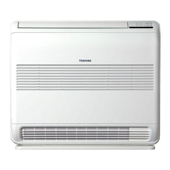
Toshiba RAS-(B)10UFV Series Installation Manual
Split type
indoor unit
outdoor unit
Hide thumbs
Also See for RAS-(B)10UFV Series:
- Owner's manual (7 pages) ,
- Installation manual (12 pages)
Advertisement
INSTALLATION MANUAL
AIR CONDITIONER (SPLIT TYPE)
Indoor unit
RAS-(B) 10, 13, 18UFV Series
Outdoor unit
RAS-10, 13, 18SAV Series
RAS-M14GAV-E
RAS-M18GAV-E
RAS-3M18SAV-E
RAS-3M26GAV-E1
RAS-4M23SAV-E
RAS-4M27GAV-E1
RAS-5M34UAV-E
ENGLISH
ESPAÑOL
FRANÇAIS
ITALIANO
DEUTSCH
PORTUGUÊS
POLSKI
ČESKY
PУCСКИЙ
HRVATSKI
MAGYAR
TÜRKÇE
NEDERLANDS
ΕΛΛΗΝΙΚΑ
SVENSKA
SUOMI
NORSK
DANSK
ROMÂNĂ
БЪЛГАРСКИ
EESTI
LATVISKI
SLOVENČINA
SLOVENŠČINA
Advertisement

Summary of Contents for Toshiba RAS-(B)10UFV Series
-
Page 1: Installation Manual
INSTALLATION MANUAL ENGLISH AIR CONDITIONER (SPLIT TYPE) ESPAÑOL FRANÇAIS ITALIANO DEUTSCH PORTUGUÊS POLSKI ČESKY PУCСКИЙ HRVATSKI MAGYAR TÜRKÇE NEDERLANDS ΕΛΛΗΝΙΚΑ SVENSKA Indoor unit RAS-(B) 10, 13, 18UFV Series SUOMI NORSK Outdoor unit DANSK RAS-10, 13, 18SAV Series ROMÂNĂ RAS-M14GAV-E RAS-M18GAV-E БЪЛГАРСКИ... -
Page 2: Table Of Contents
CONTENTS CONTENIDOS SOMMAIRE PRECAUTIONS FOR SAFETY ............1 PRECAUCIONES SOBRE SEGURIDAD ........1 MESURES DE SÉCURITÉ ............1 INSTALLATION DIAGRAM OF INDOOR AND OUTDOOR DIAGRAMA DE INSTALACIÓN DE LA UNIDAD PLAN D’INSTALLATION DES UNITÉS INTÉRIEURE ET UNITS ...................3 INTERIOR Y EXTERIOR ..............3 EXTÉRIEURE ................3 Optional Installation Parts ............3 Piezas de Instalación Opcional ..........3 Pièces d’Installation en Option ..........3... - Page 3 INHOUDSOPGAVE ΠΕΡΙΕXOΜΕΝΑ INNEHÅLL VEILIGHEIDSVOORZORGEN .............1 ΠΡOΦΥΛΑΞΕΙΣ ΑΣΦΑΛΕΙΑΣ ............1 SÄKERHETSANVISNINGAR ............1 INSTALLATIESCHEMA VOOR BINNEN- EN ΔΙΆΓΡΑΜΜΑ ΕΓΚΑΤΆΣΤΑΣΗΣ ΤΗΣ ΕΣΩΤΕΡΙΚΉΣ ΚΑΙ INSTALLATIONSSCHEMA FÖR INOMHUS- OCH BUITENMODULES ..............3 ΕΞΩΤΕΡΙΚΉΣ ΜOΝΆΔΑΣ ............3 UTOMHUSENHETEN ..............3 Προαιρετικά Eξαρτήματα Eγκατάστασης ......3 Optionele Onderdelen .............3 Valfria Installationskomponenter ..........3 BINNENMODULE ................4 ΕΣΩΤΕΡΙΚΉ...
-
Page 4: Precautions For Safety
PRECAUTIONS FOR SAFETY PRECAUTIONS FOR SAFETY Be sure to read this installation manual carefully before installing. Recommend to the owner to perform maintenance periodically when using over long periods of time. Be sure to follow the precautions provided here to avoid safety risks. The symbols and their meanings are shown below. DANGER : It indicates that incorrect use of this unit can result in a high possibility of severe injury (*1) or death. - Page 5 WARNING • Installation work must be requested from the supplying retail dealership or professional vendors. Self-installation may cause water leakage, electrical shock, or fi re as a result of improper installation. • Specifi ed tools and pipe parts for model R410A are required, and installation work must be done in accordance with the manual. HFC type refrigerant R410A has 1.6 times more pressure than that of conventional refrigerant (R22).
-
Page 6: Installation Diagram Of Indoor And Outdoor Units
INSTALLATION DIAGRAM OF INDOOR AND OUTDOOR UNITS INSTALLATION DIAGRAM OF INDOOR AND OUTDOOR UNITS Do not allow the drain hose to get slack. Air fi lter Installation plate Cut the piping hole sloped slightly. 50 mm or more 50 mm or more Make sure to run the drain hose Filter sloped downward. -
Page 7: Installation Place
INDOOR UNIT INDOOR UNIT Mounting the installation plate and screw position Installation Place (Unit : mm) • A place which provides the spaces around the indoor unit as shown in the diagram. • A place where there are no obstacles near the air inlet and outlet. •... - Page 8 2. Put water in the drain pan and make sure that the water is drained out of How to Install Indoor Unit doors. 3. When connecting extension drain hose, insulate the connecting part of extension drain hose with shield pipe. 1.
-
Page 9: Concealed Installation
Mounting directly on the fl oor. 1) Fix the leg of indoor unit on the fl oor with 2 mounting screws. 2) Fix the upper part of indoor unit on the wall with 4 mounting screws. For prevent dewfall (Floor installation) Wall burying mode Slit 2. -
Page 10: Cold Temperatures
(Front view) (Side view) 70 or more Opening for receiver 800 or more Opening for receiver 20 to 30 Partition board Partition board 50 or more 50 or more OUTDOOR UNIT OUTDOOR UNIT • When using a multi-system outdoor unit refer to the installation manual Draining off the Water provided with the model concerned. -
Page 11: Electrical Work
• Tightening torque for connection of fl are pipe Gas side 50 to 62 N·m Hexagon wrench The pressure of R410A is higher than R22 (∅12.70 mm) (5.0 to 6.2 kgf·m) is required. (Approx. 1.6 times). Therefore securely Gas side 33 to 42 N·m tighten the fl... -
Page 12: Others
OTHERS OTHERS Unit B setup. Gas Leak Test Press and hold MODE button for more than 20 seconds. When A setup changed to B setup : 5 beeps will sound and operation lamp blinks for 5 seconds. When B setup changed to A setup : 5 beep will sound. Test Operation To switch the TEST RUN (COOL) mode, press OPERATION button for 10 seconds (The beeper will make a short beep). - Page 13 1112150201-1...


