Linksys SRW224P User Manual
24-port 10/100 + 2-port gigabit switch
Hide thumbs
Also See for SRW224P:
- User manual (74 pages) ,
- Specifications (3 pages) ,
- User manual (68 pages)

Related Manuals for Linksys SRW224P


Summary of Contents for Linksys SRW224P
-
Page 1: User Guide
® A Division of Cisco Systems, Inc. 24-Port 10/100 + 2-Port Gigabit Switch User Guide with WebView and Power over Ethernet WIRED SRW224P Model No. - Page 2 24-Port 10/100 + 2-Port Gigabit Switch with Webview and Power over Ethernet Copyright and Trademarks Specifications are subject to change without notice. Linksys is a registered trademark or trademark of Cisco Systems, Inc. and/or its affiliates in the U.S. and certain other countries. Copyright © 2005 Cisco Systems, Inc. All rights reserved.
-
Page 3: Table Of Contents
24-Port 10/100 + 2-Port Gigabit Switch with Webview and Power over Ethernet Table of Contents Chapter 1: Introduction Welcome What’s in this Guide? Chapter 2: Getting to Know the Switch The Front Panel The Back Panel The Side Panel RJ-45 Ports... - Page 4 24-Port 10/100 + 2-Port Gigabit Switch with Webview and Power over Ethernet Help Appendix A: Fast Ethernet and Gigabit Ethernet About Fast Ethernet About Gigabit Ethernet Appendix B: Cabling Overview Twisted Pair Cabling Fiber Optic Cabling Appendix C: Glossary Appendix D: Specifications...
- Page 5 24-Port 10/100 + 2-Port Gigabit Switch with Webview and Power over Ethernet List of Figures Figure 2-1: Front Panel Figure 2-2: Back Panel Figure 2-3: Side Panel Figure 3-1: Typical Network Configuration Figure 3-2: Attaching the Switch’s Rubber Feet Figure 3-3: Attaching Brackets to the Switch...
- Page 6 24-Port 10/100 + 2-Port Gigabit Switch with Webview and Power over Ethernet Figure 4-24: Port Configuration Figure 4-25: PoE Main Menu Figure 4-26: Power Configuration Figure 4-27: Power Port Status Figure 4-28: Power Port Configuration Figure 4-29: Logout Figure 5-1: Address Field Figure 5-2: Password Screen Figure 5-3: Sys.
- Page 7 24-Port 10/100 + 2-Port Gigabit Switch with Webview and Power over Ethernet Figure 5-28: QoS - IP Precedence/DSCP Figure 5-29: QoS - IP Port Figure 5-30: QoS - ACL Priority Figure 5-31: QoS - Rate Limit Figure 5-32: DiffServ - Diffserv Class Map...
- Page 8 24-Port 10/100 + 2-Port Gigabit Switch with Webview and Power over Ethernet Figure 5-61: Spanning Tree - Port/LAG Info Figure 5-62: Spanning Tree - Information Figure 5-63: SNMP - SNMP Config Figure 5-64: IGMP - IGMP Conf Figure 5-65: IGMP - IGMP Router Info...
-
Page 9: Chapter 1: Introduction
Use the instructions in this User Guide to help you connect the Switch, set it up, and configure it to bridge your different networks. These instructions should be all you need to get the most out of the 24-port 10/100 + 2-Port Gigabit Switch with WebView and Power over Ethernet. -
Page 10: What's In This Guide
This appendix supplies the Switch’s warranty information. • Appendix F: Regulatory Information This appendix supplies the Switch’s regulatory information. • Appendix G: Contact Information This appendix provides contact information for a variety of Linksys resources, including Technical Support. Chapter 1: Introduction What’s in this Guide? -
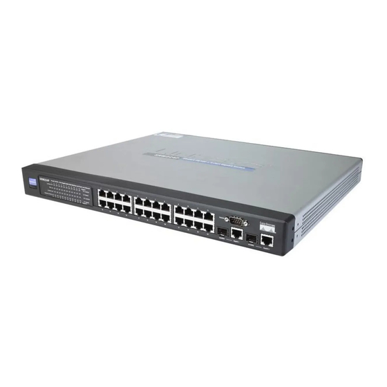
Page 11: Chapter 2: Getting To Know The Switch
Figure 2-1: Front Panel LEDs System A green LED indicates that power is being supplied to the Switch. A solid, amber LED indicates that the Switch’s power-on-self-test (POST) is in progress, but when this blinks amber that indicates that the POST has failed. -
Page 12: The Back Panel
The Power port is where you will connect the power cord. The Side Panel A security slot, where you can attach a lock to protect the Switch, is located on a side panel Chapter 2: Getting to Know the Switch... -
Page 13: Rj-45 Ports
(for configuration purposes) using the provided serial cable. You can use HyperTerminal to manage the Switch using the console port. With this and many other Linksys products, your networking options are limitless. Go to the Linksys website at www.linksys.com for more information about products that work with the Switch. -
Page 14: Chapter 3: Connecting The Switch
24-Port 10/100 + 2-Port Gigabit Switch with Webview and Power over Ethernet Chapter 3: Connecting the Switch Overview This chapter will explain how to connect network devices to the Switch. The following diagram shows a typical network configuration. Figure 3-1: Typical Network Configuration When you connect your network devices, make sure you don’t exceed the maximum cabling distances, which are... -
Page 15: Pre-Installation Considerations
As previously mentioned, the Switch provides full-duplex support for its RJ-45 ports. Full-duplex operation allows data to be sent and received simultaneously, doubling a port’s potential data throughput. If you will be using the Switch in full-duplex mode, the maximum cable length using Category 5 cable is 328 feet (100 meters). -
Page 16: Hardware Installation
6. If you are using a mini-GBIC port, then connect a mini-GBIC module to the mini-GBIC port. For detailed instructions, refer to the module’s documentation. 7. Connect the supplied power cord to the Switch’s power port, and plug the other end into an electrical outlet. When connecting power, always use a surge protector. -
Page 17: Uplinking The Switch
Uplinking the Switch To uplink the Switch, connect one end of a Cat5 (or better) cable into one of the 24 10/100 ports, and then connect the other end of the cable into the peripheral device’s uplink port. MDI/MDIX will automatically detect the speed and cable type. -
Page 18: Chapter 4: Configuration Using The Console Interface
Select HyperTerminal to run the utility program. 2. Enter a name for this connection. In the example shown, the name of connection is SRW224P. Select an icon for the application. Click OK. -
Page 19: Configuring The Switch Through The Console Interface
24-Port 10/100 + 2-Port Gigabit Switch with Webview and Power over Ethernet Configuring the Switch through the Console Interface Login When you finish configuring HyperTerminal, the Login screen will appear. The first time you open the console interface, use the default username admin, and leave the password blank. You can set a new password later from the Password Setting screen. -
Page 20: Figure 4-6: Switch Main Menu
24-Port 10/100 + 2-Port Gigabit Switch with Webview and Power over Ethernet Switch Main Menu The Main Menu screen displays six menu choices: System Configuration Menu, Port Status, Port Configuration, PoE Configuration, Help, and Logout. System Configuration Menu System Configuration Menu displays: 1. -
Page 21: Figure 4-8: System Information
The version screen displays the Boot Version, Software Version, Loader Version and the Hardware Version. Boot Version. This file runs when the Switch is turned on. It loads the operating system for the Switch. Software Version. This file contains the programming code that runs the Switch. -
Page 22: Figure 4-11: Serial Port Configuration
Figure 4-11: Serial Port Configuration CPU Performance The CPU performance screen displays the percentage of processor power being used by the Switch. Figure 4-12: CPU Performance Chapter 4: Configuration using the Console Interface Configuring the Switch through the Console Interface... -
Page 23: Figure 4-13: User And Password Settings
User and Password Settings The User & Password Settings screen displays user account information on the Switch. The default account is the administrator account. To add a new user, use the arrow keys to select edit then enter the username of the new account and assign a password to the account. -
Page 24: Figure 4-14: Ip Configuration
Management VLAN. Set the ID number of the Management VLAN. This is the only VLAN through which you can gain management access to the Switch. By default, all ports on the Switch are members of VLAN 1, so a management station can be connected to any port on the Switch. However, if other VLANs are configured and you change the Management VLAN, you may lose management access to the Switch. -
Page 25: Figure 4-17: Snmp
24-Port 10/100 + 2-Port Gigabit Switch with Webview and Power over Ethernet SNMP The SNMP screen allows you to set the Switch’s SNMP settings. SNMP Server. Enable or Disable the SNMP function for the Switch. SNMP Port. Set the TCP port that will be used for sending and receiving SNMP packets. -
Page 26: Figure 4-19: File Management
File Management The File Management screen allows you to upload and download files to the Switch using TFTP. Source File. Specify the location of the file to transfer. Select TFTP if the file is on a TFTP server, Image if the file is a local image file, or startup-config if the file is a local configuration file. -
Page 27: Figure 4-20: Restore System Default Settings
Restore System Default Setting To restore the Switch back to the factory default settings, select Restore System Default Setting and press Enter. A confirmation message will appear stating that All User Configuration data will be reset to Default. Continue? [y/ n]. -
Page 28: Figure 4-22: Back To Main Menu
24-Port 10/100 + 2-Port Gigabit Switch with Webview and Power over Ethernet Back to Main Menu Select Back to Main Menu if you want to return to the main menu. Figure 4-22: Back to Main Menu Chapter 4: Configuration using the Console Interface... -
Page 29: Figure 4-23: Port Status
24-Port 10/100 + 2-Port Gigabit Switch with Webview and Power over Ethernet Port Status This screen allows you to view the status of a port. The Port, Enable, Link Status, Spd/Dpx, and Flow Control are displayed. Ports 1 through 24 are ethernet RJ-45 ports and ports 25 and 26 are Gigabit RJ-45 ports, Giga1 and Giga2. Each Gigabit port has a shared mini-Gbic port. -
Page 30: Figure 4-25: Poe Main Menu
Port power can be automatically turned on and off for connected devices, and a per- port power priority can be set so that the Switch never exceeds its allocated power budget. When a device is connected to a port, its power requirements are detected by the Switch before power is supplied. If the power required by a device exceeds the power budget of the port or the whole Switch, power is not supplied. -
Page 31: Figure 4-28: Power Port Configuration
24-Port 10/100 + 2-Port Gigabit Switch with Webview and Power over Ethernet Port PoE Configuration The Power Port Configuration screen allows you to set the PoE settings for each port. Select the edit action and use the left-right and up-down arrows to select the attribute you would like to set. You can set the Admin Status, the Priority and the Power Allocation. -
Page 32: Chapter 5: Configuring The Switch Through The Web Utility
The first screen that appears displays the System Description screen for the Sys.Info tab. There are 14 tabs that run across the top of the screen: Sys.Info, IP Conf, Switch Conf., QoS, DiffServ, Security, SNTP, Statistics, PoE, Spanning Tree, SNMP, IGMP, Maintenance and Help. Each tab contains further screens, described in this chapter, to help you configure and manage the Switch. -
Page 33: System Information
System up time. Length of time the management agent has been up. IP Address. The IP Address assigned to the Switch is displayed. (The default IP address is 192.168.1.254.) Base MAC Address. The MAC Address of the switch is displayed. -
Page 34: Figure 5-5: Sys. Info - System Mode
The current setting for jumbo frames can be displayed with the show system command. Use the drop-down menu to Enable or Disable the transmitting and receiving of Jumbo Frames for this switch. Chapter 5: Configuring the Switch through the Web Utility... -
Page 35: Figure 5-6: Sys. Info - Forwarding Database
24-Port 10/100 + 2-Port Gigabit Switch with Webview and Power over Ethernet Forwarding Database The Forwarding Database screen displays the following information. Aging Status. This feature, when enabled, discards dynamic MAC addresses after a set amount of time. Aging Interval. This is the amount of time after which dynamic address table entries are discarded. -
Page 36: Figure 5-7: Dynamic Address Screen
Static address A static address can be assigned to a specific interface on this switch. Static addresses are bound to the assigned interface and will not be moved. When a static address is seen on another interface, the address will be ignored and will not be written to the address table. -
Page 37: Figure 5-9: Sys. Info - Time Synchronization Screen
(SNTP or NTP). Maintaining an accurate time on the switch enables the system log to record meaningful dates and times for event entries. If the clock is not set, the switch will only record the time from the factory default set at the last bootup. -
Page 38: Figure 5-10: Sys. Info - Cpu Performance
24-Port 10/100 + 2-Port Gigabit Switch with Webview and Power over Ethernet CPU Performance The CPU Performance screen displays the current percentage of processor power being used by the switch. Figure 5-10: Sys. Info - CPU Performance Logout To logout, click the Logout hyper-link. Then click OK to proceed or Cancel to cancel. Then click Yes to close the window or No to cancel. -
Page 39: Ip Config
Figure 5-12: IP Config - IP Address An IP address may be used for management access to the switch over your network. You may also need to establish a default gateway between the switch and management stations that exist on another network segment. - Page 40 24-Port 10/100 + 2-Port Gigabit Switch with Webview and Power over Ethernet Select the IP Address Mode using the drop-down menu. Selecting Static will allow you to enter a static IP address, subnet mask and default gateway using the text field provided. Selecting BOOTP or DHCP disables these text boxes and auto assigns an IP address.
-
Page 41: Switch Config
Use the full-duplex mode on ports whenever possible to double the throughput of switch connections. Flow control should also be enabled to control network traffic during periods of congestion and prevent the loss of packets when port buffer thresholds are exceeded. -
Page 42: Figure 5-14: Edit Port Configuration Screen
You can use Port Configuration to enable/disable an interface, set auto-negotiation and the interface capabilities to advertise, or manually force the speed, duplex mode, and flow control. This screen allows you to edit the following information for each port on the switch. Name. Allows you to label an interface. (Range: 1-64 characters) Admin. - Page 43 Flow control can eliminate frame loss by “blocking” traffic from end stations or segments connected directly to the switch when its buffers fill. When enabled, back pressure is used for half-duplex operation and IEEE 802.3x for full-duplex operation. (Avoid using flow control on a port connected to a hub unless it is actually required to solve a problem.
-
Page 44: Figure 5-15: Switch Config - Vlan
24-Port 10/100 + 2-Port Gigabit Switch with Webview and Power over Ethernet VLAN A VLAN is a group of ports that can be located anywhere in the network, but communicate as though they belong to the same physical segment. VLANs help to simplify network management by allowing you to move devices to a new VLAN without having to change any physical connections. -
Page 45: Figure 5-16: Adding/Editing Vlan Screen
24-Port 10/100 + 2-Port Gigabit Switch with Webview and Power over Ethernet Create VLAN To create a VLAN, enter the VLAN ID and VLAN name, up to 32 characters long. Mark the Enable checkbox to activate the VLAN, and click Create VLAN. -
Page 46: Figure 5-17: Switch Config - Vlan Port
24-Port 10/100 + 2-Port Gigabit Switch with Webview and Power over Ethernet VLAN Port You can configure VLAN behavior for specific interfaces, including the default VLAN identifier (PVID), accepted frame types, ingress filtering and mode. VLAN identifier (PVID). VLAN ID assigned to untagged frames received on the interface. (Default: 1) •... -
Page 47: Figure 5-18: Switch Config - Lag Configuration
You can create up to four lags on the switch. Each lag can contain up to eight ports. -
Page 48: Figure 5-19: Create Lag Screen
24-Port 10/100 + 2-Port Gigabit Switch with Webview and Power over Ethernet Create LAG Enter a lag ID of 1-4 in the Lag field, select any of the switch ports from the scroll-down port list, and click Add. LAG Broadcast Control Set the threshold for any lag, click Submit. -
Page 49: Figure 5-22: Switch Config - Port Mirroring
24-Port 10/100 + 2-Port Gigabit Switch with Webview and Power over Ethernet Port Mirroring You can mirror traffic from any source port to a target port for real-time analysis. You can then attach a logic analyzer or RMON probe to the target port and study the traffic crossing the source port in a completely unobtrusive manner. -
Page 50: Figure 5-23: Switch Config - Lacp
LACP. Set Port Actor – This menu sets the local side of an aggregate link; that is, the ports on this switch. Set Port Partner – This menu sets the remote side of an aggregate link; that is, the ports on the attached device. -
Page 51: Qos
24-Port 10/100 + 2-Port Gigabit Switch with Webview and Power over Ethernet The QoS tab includes links to the following screens. • CoS Settings • Queue Settings • CoS to Queue • IP Precedence/DSCP • IP Port • ACL Priority •... -
Page 52: Figure 5-25: Qos - Cos Settings
Class of Service (CoS) allows you to specify which data packets have greater precedence when traffic is buffered in the switch due to congestion. This switch supports CoS with four priority queues for each port. Data packets in a port’s high-priority queue will be transmitted before those in the lower-priority queues. You can set the default priority for each interface, and configure the mapping of frame priority tags to the switch’s priority queues. -
Page 53: Figure 5-26: Qos - Queue Settings
Queue Mode (Global). You can set the switch to service the queues based on a strict rule that requires all traffic in a higher priority queue to be processed before lower priority queues are serviced, or use Weighted Round- Robin (WRR) queuing that specifies a relative weight of each queue. -
Page 54: Figure 5-28: Qos - Ip Precedence/Dscp
Precedence or six bits for Differentiated Services Code Point (DSCP) service. When these services are enabled, the priorities are mapped to a Class of Service value by the switch, and the traffic then sent to the corresponding output queue. Because different priority information may be contained in the traffic, this switch maps priority... -
Page 55: Figure 5-29: Qos - Ip Port
24-Port 10/100 + 2-Port Gigabit Switch with Webview and Power over Ethernet IP Port You can also map network applications to Class of Service values based on the IP port number (i.e., TCP/UDP port number) in the frame header. Some of the more common TCP service ports include: HTTP: 80, FTP: 21, Telnet: 23 and POP3: 110. -
Page 56: Figure 5-30: Qos - Acl Priority
24-Port 10/100 + 2-Port Gigabit Switch with Webview and Power over Ethernet ACL Priority Use ACL CoS Mapping to set the output queue for packets matching an ACL rule as shown in the following table. Note that the specified CoS value is only used to map the matching packet to an output queue; it is not written to the packet itself. -
Page 57: Figure 5-31: Qos - Rate Limit
Rate limiting is configured on interfaces at the edge of a network to limit traffic coming out of the switch. Traffic that falls within the rate limit is transmitted, while packets that exceed the acceptable amount of traffic are dropped. -
Page 58: Diffserv
24-Port 10/100 + 2-Port Gigabit Switch with Webview and Power over Ethernet DiffServ The commands described in this section are used to configure Quality of Service (QoS) classification criteria and service policies. Differentiated Services (DiffServ) provides policy-based management mechanisms used for prioritizing network resources to meet the requirements of specific traffic types on a per hop basis. -
Page 59: Figure 5-32: Diffserv - Diffserv Class Map
24-Port 10/100 + 2-Port Gigabit Switch with Webview and Power over Ethernet DiffServ Class Map A class map is used for matching packets to a specified class. Class Name. Name of the class map. (Range: 1-32 characters) Type. Only one match command is permitted per class map, so the match-any field refers to the criteria specified by the lone match command. -
Page 60: Figure 5-34: Diffserv Class Map - Adding A Class
24-Port 10/100 + 2-Port Gigabit Switch with Webview and Power over Ethernet Add rules to a selected class using the ACL list drop-down menu and the IP DSCP, IP Precedence and VLAN text fields provided then click Add. Adding a Class Class Name. -
Page 61: Figure 5-35: Diffserv - Diffserv Policy Map
24-Port 10/100 + 2-Port Gigabit Switch with Webview and Power over Ethernet DiffServ Policy Map This function creates a policy map that can be attached to multiple interfaces. Modify Name and Description. Configures the name and a brief description of a policy map. (Range: 1-32 characters for the name;... -
Page 62: Figure 5-37: Diffserv Policy Map - Setting Rules
24-Port 10/100 + 2-Port Gigabit Switch with Webview and Power over Ethernet Meter. The maximum throughput and burst rate. • Rate (kbps) – Rate in kilobits per second. • Burst (byte) – Burst in bytes. Exceed Action. Specifies whether the traffic that exceeds the specified rate will be dropped or the DSCP service level will be reduced. -
Page 63: Figure 5-38: Diffserv - Diffserv Service Policy
24-Port 10/100 + 2-Port Gigabit Switch with Webview and Power over Ethernet DiffServ Service Policy This function binds a policy map to the ingress queue of a particular interface. Check Enabled and choose a Policy Map for a port from the drop-down menu. -
Page 64: Security
24-Port 10/100 + 2-Port Gigabit Switch with Webview and Power over Ethernet Security The Security tab includes links to the following screens. • ACL Conf. • ACL Port Binding • 802.1xUsers • 802.1xPort Conf. • Radius Server • Port Security •... -
Page 65: Figure 5-40: Acl Conf - Adding/Editing Standard Acl
24-Port 10/100 + 2-Port Gigabit Switch with Webview and Power over Ethernet Standard ACL To configure a standard ACL do the following. Specify the action (that is, Permit or Deny). Select the address type (Any, Host, or IP). If you select “Host,” enter a specific address. - Page 66 24-Port 10/100 + 2-Port Gigabit Switch with Webview and Power over Ethernet Protocol. Specifies the protocol type to match as TCP, UDP or Others, where others indicates a specific protocol number (0-255). (Options: TCP, UDP, Others; Default: TCP) Source/Destination Port (0-65535). Source/destination port number for the specified protocol type. (Range: 0- 65535) Control Code (0-63).
-
Page 67: Figure 5-42: Acl Conf - Adding/Editing Mac Acl
24-Port 10/100 + 2-Port Gigabit Switch with Webview and Power over Ethernet MAC ACL To configure a MAC ACL do the following. Specify the action (that is, Permit or Deny). Specify the source and/or destination addresses. Select the address type (Any, Host, or MAC). If you select “Host,” enter a specific address (for example, 11-22-33-44-55-66). If you select “MAC,”... -
Page 68: Figure 5-43: Security - Acl Port Binding
After configuring Access Control Lists (ACL), you should bind them to the ports that need to filter traffic. You can assign one IP access list to any port, but you can only assign one MAC access list to all the ports on the switch. -
Page 69: Figure 5-44: Security - 802.1X Users
When a client (i.e., Supplicant) connects to a switch port, the switch (i.e., Authenticator) responds with an EAPOL identity request. The client provides its identity (such as a user name) in an EAPOL response to the switch, which it forwards to the RADIUS server. The RADIUS server verifies the client identity and sends an access challenge back to the client. -
Page 70: Figure 5-45: Security - 802.1X Port Conf
When 802.1X is enabled, you need to configure the parameters for the authentication process that runs between the client and the switch (that is, authenticator), as well as the client identity lookup process that runs between the switch and authentication server. These parameters are described in this section. -
Page 71: Figure 5-47: Security - Port Security
Port Security Port security is a feature that allows you to configure a switch port with one or more device MAC addresses that are authorized to access the network through that port. When port security is enabled on a port, the switch stops learning new MAC addresses on the specified port when it has reached a configured maximum number. -
Page 72: Figure 5-49: Security - Https Settings
24-Port 10/100 + 2-Port Gigabit Switch with Webview and Power over Ethernet HTTPS Settings You can configure the switch to enable the Secure Hypertext Transfer Protocol (HTTPS) over the Secure Socket Layer (SSL), providing secure access (that is, an encrypted connection) to the switch’s web interface. -
Page 73: Sntp
The SNTP tab includes links to the Global Settings screen. Global Settings Simple Network Time Protocol (SNTP) allows the switch to set its internal clock based on periodic updates from a time server (SNTP or NTP). Maintaining an accurate time on the switch enables the system log to record Figure 5-51: SNTP - Global Settings meaningful dates and times for event entries. -
Page 74: Statistics
24-Port 10/100 + 2-Port Gigabit Switch with Webview and Power over Ethernet Statistics You can display standard statistics on network traffic from the Interfaces Group and Ethernet-like MIBs, as well as a detailed breakdown of traffic based on the RMON MIB. Interfaces and Ethernet-like statistics display errors on the traffic passing through each port. -
Page 75: Figure 5-53: Statistics - Etherlike Statistics
24-Port 10/100 + 2-Port Gigabit Switch with Webview and Power over Ethernet Etherlike Statistics To view the Etherlike statistics for a port or lag, select the required interface from the drop-down menu and click Refresh. Figure 5-53: Statistics - Etherlike Statistics... -
Page 76: Poe
• Power Status Power Config A maximum PoE power budget for the switch (power available to all switch ports) can be defined so that power can be centrally managed, preventing overload conditions at the power source. If the power demand from devices connected to the switch exceeds the power budget setting, the switch uses port power priority settings to limit the supplied power. -
Page 77: Figure 5-56: Poe - Power Port Config
Power Port Config If a device is connected to a switch port and the switch detects that it requires more than the power budget of the port, no power is supplied to the device (that is, port power remains off). -
Page 78: Figure 5-58: Poe - Power Status
24-Port 10/100 + 2-Port Gigabit Switch with Webview and Power over Ethernet Power Status This screen displays the following information. Maximum Available Power System Operation Status Mainpower Consumption Figure 5-58: PoE - Power Status Software Version Chapter 5: Configuring the Switch through the Web Utility... -
Page 79: Spanning Tree
The Spanning Tree Algorithm (STA) can be used to detect and disable network loops, and to provide backup links between switches, bridges or routers. This allows the switch to interact with other bridging devices (that is, an STA-compliant switch, bridge or router) in your network to ensure that only one route exists between any two stations on the network, and provide backup links which automatically take over when a primary link goes down The Spanning Tree tab includes links to the following screens. -
Page 80: Figure 5-59: Spanning Tree - Information
Root Port. The number of the port on this switch that is closest to the root. This switch communicates with the root device through this port. If there is no root port, then this switch has been accepted as the root device of the Spanning Tree network. -
Page 81: Figure 5-60: Spanning Tree - Configuration
24-Port 10/100 + 2-Port Gigabit Switch with Webview and Power over Ethernet Configuration Configure the global settings for STA using this screen. Global settings apply to the entire switch. Modify the required attributes for STA. Click Submit to save the changes. -
Page 82: Figure 5-62: Spanning Tree - Information
24-Port 10/100 + 2-Port Gigabit Switch with Webview and Power over Ethernet Port/LAG Conf You can configure RSTP attributes for specific interfaces, including port priority, path cost, link type, and edge port. You may use a different priority or path cost for ports of the same media type to indicate the preferred path, link type to indicate a point-to-point connection or shared-media connection, and edge port to indicate if the attached device can support fast forwarding. -
Page 83: Snmp
Traps indicating status changes are issued by the switch to specified trap managers. You must specify trap managers so that key events are reported by this switch to your management station (using network management platforms such as HP OpenView). -
Page 84: Igmp
The Internet Group Management Protocol (IGMP) runs between hosts and their immediately adjacent multicast router/switch. IGMP is a multicast host registration protocol that allows any host to inform its local router that it wants to receive transmissions addressed to a specific multicast group. -
Page 85: Figure 5-64: Igmp - Igmp Conf
This is also referred to as IGMP Snooping. (Default: Enabled). Act as IGMP Querier. When enabled, the switch can serve as the Querier, which is responsible for asking hosts if they want to receive multicast traffic. (Default: Enabled). -
Page 86: Figure 5-65: Igmp - Igmp Router Info
Therefore, if the IGMP querier is a known multicast router/ switch connected over the network to an interface (port or lag) on the Switch, you can manually configure the interface (and a specified VLAN) to join all the current multicast groups supported by the attached router. This can ensure that multicast traffic is passed to all the... -
Page 87: Figure 5-67: Igmp - Ip Multicast Reg Table
You can display the port members associated with a specified VLAN and multicast IP address. Select a VLAN ID and the IP address for a multicast service from the drop-down menus. The switch will display all the interfaces that are propagating this multicast service. -
Page 88: Maintenance
• Save Config • Integrated Cable Test Reset To restart the switch, click the Reset the Device link, then click Yes to restart the switch. To cancel the restart, click No or Cancel, then click OK. Figure 5-69: Maintenance - Reset File Download Downloads switch firmware or configuration files from a TFTP server. -
Page 89: Figure 5-71: Maintenance - File Upload
File Upload Uploads switch firmware or configuration files to a TFTP server. You must specify the file type to transfer, along with TFTP server IP address and file names as required. Saving firmware and configuration files on a TFTP server enables them to be later downloaded to the switch to restore operation. -
Page 90: Help
24-Port 10/100 + 2-Port Gigabit Switch with Webview and Power over Ethernet Integrated Cable Test To test the connection quality of cables, click on the test icon for the port. The following screen will display the last test results. Click the Submit button to start the test. -
Page 91: Appendix A: Fast Ethernet And Gigabit Ethernet
24-Port 10/100 + 2-Port Gigabit Switch with Webview and Power over Ethernet Appendix A: Fast Ethernet and Gigabit Ethernet About Fast Ethernet 1. As the demand for desktop video, multimedia development, imaging, and other speed-intensive applications continues to rise, the need for high performance, fault tolerant LAN technology will become more critical. -
Page 92: Appendix B: Cabling
Each fiber optic cable is tipped with a connector that fits into a fiber port on a network adapter, hub, or switch. In the U. S., most cables use a square SC connector that slides and locks into place when plugged into a port or connected to another cable. -
Page 93: Appendix C: Glossary
24-Port 10/100 + 2-Port Gigabit Switch with Webview and Power over Ethernet Appendix C: Glossary This glossary contains some basic networking terms you may come across when using this product. For more advanced terms, see the complete Linksys glossary at http:// www.linksys.com/glossary. - Page 94 24-Port 10/100 + 2-Port Gigabit Switch with Webview and Power over Ethernet Full Duplex - The ability of a networking device to receive and transmit data simultaneously. Gateway - A device that interconnects networks with different, incompatible communications protocols. Half Duplex - Data transmission that can occur in two directions over a single line, but only one direction at a time.
- Page 95 24-Port 10/100 + 2-Port Gigabit Switch with Webview and Power over Ethernet Switch - 1. A data switch that connects computing devices to host computers, allowing a large number of devices to share a limited number of ports. 2. A device for making, breaking, or changing the connections in an electrical circuit.
-
Page 96: Appendix D: Specifications
24-Port 10/100 + 2-Port Gigabit Switch with Webview and Power over Ethernet Appendix D: Specifications Standards IEEE Std. 802.3-2002 Ports 24 - 10/100 , 2 - 10/100/1000, 2 - MiniGBIC, 1- Console Cabling Type UTP CAT 5e or better LEDs... -
Page 97: Appendix E: Warranty Information
Linksys warrants to You that, for a period of five years (the “Warranty Period”), your Linksys Product will be substantially free of defects in materials and workmanship under normal use. Your exclusive remedy and Linksys' entire liability under this warranty will be for Linksys at its option to repair or replace the Product or refund Your purchase price less any rebates. -
Page 98: Appendix F: Regulatory Information
24-port 10/100 + 2-Port Gigabit Switch with WebView and Power over Ethernet Appendix F: Regulatory Information FCC STATEMENT This equipment has been tested and found to comply with the limits for a Class A digital device, pursuant to part 15 of the FCC Rules. These limits are designed to provide reasonable protection against harmful interference when the equipment is operated in a commercial environment. - Page 99 24-port 10/100 + 2-Port Gigabit Switch with WebView and Power over Ethernet Safety Compliance Warning: Fiber Optic Port Safety When using a fiber optic port, never look at the transmit laser while it is powered on. Also, never look directly at the fiber TX port and fiber cable ends when...
- Page 100 The mains cord must be <HAR> or <BASEC> marked and be of type HO3VVF3GO.75 (minimum). IEC-320 receptacle. Veuillez lire à fond l'information de la sécurité suivante avant d'installer le Switch: AVERTISSEMENT: L’installation et la dépose de ce groupe doivent être confiés à un personnel qualifié.
- Page 101 24-port 10/100 + 2-Port Gigabit Switch with WebView and Power over Ethernet L’appareil fonctionne à une tension extrêmement basse de sécurité qui est conforme à la norme IEC 60950. Ces conditions ne sont maintenues que si l’équipement auquel il est raccordé...
- Page 102 Warning: When connecting this device to a power outlet, connect the field ground lead on the tri-pole power plug to a valid earth ground line to prevent electrical hazards. Warning: This switch uses lasers to transmit signals over fiber optic cable. The lasers are compliant with the requirements of a Class 1 Laser Product and are inherently eye safe in normal operation.
- Page 103 All printed documentation for this product uses biodegradable paper that originates from sustained and managed forests. The inks used in the printing process are non-toxic. Purpose This guide details the hardware features of the switch, including Its physical and performance-related characteristics, and how to install the switch. Audience This guide is for system administrators with a working knowledge of network management.
-
Page 104: Appendix G: Contact Information
Can't find information about a product you want to buy on the web? Do you want to know more about networking with Linksys products? Give our advice line a call at: Or fax your request in to: If you experience problems with any Linksys product,...