Table of Contents
Advertisement
Quick Links
Download this manual
See also:
User Manual
Advertisement
Table of Contents

Related Manuals for RuggedCom RuggedSwitch RS900 Family


Summary of Contents for RuggedCom RuggedSwitch RS900 Family
-
Page 1: Installation Guide
® RuggedSwitch RS900 Family Industrially Hardened Ethernet Switches Installation Guide July 21, 2010 www.ruggedcom.com... - Page 2 We have checked the contents of this manual against the hardware and software described. However, deviations from the description cannot be completely ruled out. RuggedCom shall not be liable for any errors or omissions contained herein or for consequential damages in connection with the furnishing, performance, or use of this material.
-
Page 3: Federal Communications Commission Radio Frequency Interference Statement
2010 RuggedCom Inc. Rev107... -
Page 4: Table Of Contents
Serial Ports Specifications................40 Mechanical Specifications ................41 Type Tests ......................42 IEC 61850-3 Type Tests ................. 42 IEEE 1613 Type Tests ..................43 IEC Environmental Type Tests................ 43 Agency Approvals ....................44 Warranty........................44 2010 RuggedCom Inc. Rev107... -
Page 5: Table Of Figures
Figure 14 - 100FX LC connector Figure 15: DB9 Female DCE Port pin-out Figure 16: RJ45 Port pin-out Figure 17: Fiber Serial Interface (ST Connector) Figure 18: Conceptual recommended RS485 wiring diagram Figure 19 - Mechanical Specifications 2010 RuggedCom Inc. Rev107... -
Page 6: Table Of Tables
Table 23: Fiber Optic Port Specification................40 Table 24 - Mechanical Specifications................41 Table 25 - IEC 61850-3 Type Tests ................42 Table 26 - IEEE 1613 Type Tests ................... 43 Table 27 - Environmental Type Tests ................43 2010 RuggedCom Inc. Rev107... -
Page 7: Product Overview
Multimode and Singlemode optical transceivers Long haul optics allow distances up to 90 km Advanced layer-2 switching functions including Flow-Control, Link Aggregation, MAC Bridges, Rapid Spanning Tree, Message Prioritization, VLANs and Port Based Network Access Control 2010 RuggedCom Inc. Rev107... -
Page 8: Ruggedswitch
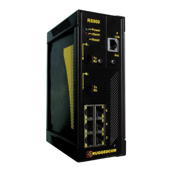
RS900 Family Installation Guide ® 1.2 RuggedSwitch RS900 9 Port Fiber Optic Ethernet Switch Up to 9 fast Ethernet ports Copper and fiber options 2010 RuggedCom Inc. Rev107... -
Page 9: Ruggedwireless™ Family Of Products
1 Wireless interface 1 Wireless interface Up to 8 fast Ethernet ports RS485/RS422/RS232 Serial ports (DB9 or RJ45); Serial Fiber Copper and fiber options interface (ST) available 2 Optional Ethernet ports 2010 RuggedCom Inc. Rev107... - Page 10 RS485/RS422/RS232 Serial 6 fast Ethernet ports ports (DB9 or RJ45); Serial Fiber interface (ST) available Port 9 Antenna #1 Port 7 Ethernet over VDSL Ports 1 & Serial Power & Alarm Port 9 Antenna #2 2010 RuggedCom Inc. Rev107...
-
Page 11: Ruggedvdsl™ Family Of Products
(DB9 or RJ45); Serial Fiber interface Copper and fiber options (ST) available 2 Optional Ethernet ports Port 9 Ports 3 & 4 Ethernet 10/100Base-TX over VDSL 100Base-FX Ports 1 & 2 Serial Power & Alarm 2010 RuggedCom Inc. Rev107... - Page 12 RS485/RS422/RS232 Serial 6 fast Ethernet ports ports (DB9 or RJ45); Serial Fiber interface (ST) available Port 9 Ethernet over VDSL Port 3 Ethernet over VDSL Ports 1 & 2 Serial Power & Alarm 2010 RuggedCom Inc. Rev107...
-
Page 13: Ruggedserver
2-Port Serial Device Server with up to 3 Ethernet Ports 2 RS485/RS422/RS232 Serial ports (DB9 or RJ45); Serial Fiber interface (ST) available Up to 3 fast Ethernet ports Copper and fiber options 2010 RuggedCom Inc. Rev107... -
Page 14: Front Panel Description
RS900 Family Installation Guide 1.6 Front Panel Description Figure 1 - Front Panel Description Status LED Colour Activity Comments Power LED Green Solid Power On Alarm LED Solid Alarm condition exists Table 1 - Status LEDs 2010 RuggedCom Inc. Rev107... -
Page 15: Bottom Panel Description
RS900 Family Installation Guide 1.7 Bottom Panel Description Console Port Chassis Ground Power Port Failsafe Relay Optional Din-Rail Mounting Bracket Figure 2 - Bottom Panel Description 2010 RuggedCom Inc. Rev107... -
Page 16: Installation
RS900 Family Installation Guide 2 Installation 2.1 Din Rail Mounting An optional DIN rail-mounting bracket is available for the unit. The figure below details mounting instructions for the standard 1” DIN Rail. Figure 3 – DIN Rail Mounting 2010 RuggedCom Inc. Rev107... -
Page 17: Power Supply Wiring And Grounding
2. All line-to-ground transient energy is shunted to the Surge Ground terminal. In cases where users require the inputs to be isolated from ground, remove the ground braid between Surge and Chassis Ground. Note that all line-to-ground transient protection circuitry will be disabled. 2010 RuggedCom Inc. Rev107... -
Page 18: Figure 5 - Dc Power Supply Wiring And Grounding Diagram
2. All line-to-ground transient energy is shunted to the Surge Ground terminal. In cases where users require the inputs to be isolated from ground, remove the ground braid between Surge and Chassis Ground. Note that all line-to-ground transient protection circuitry will be disabled. 2010 RuggedCom Inc. Rev107... -
Page 19: Figure 6 - Failsafe Output Relay
The Failsafe output relay is provided to signal critical error conditions that may occur on the unit. The contacts are energized upon power up of the unit and remain energized until an alarm condition or power loss occurs. Figure 6 - Failsafe Output Relay 2010 RuggedCom Inc. Rev107... -
Page 20: Figure 7 - Dielectric Strength Testing
This is required in order to prevent the surge suppression circuitry, which is connected to surge ground, from being activated. Figure 7 - Dielectric Strength Testing 2010 RuggedCom Inc. Rev107... -
Page 21: Console Port Wiring
No Connection No Connection No Connection Table 2 - RS232 Female DCE pin-out NOTE: This port is not intended to be a permanent connection and the cable shall be less than 2m (6.5 ft) in length. 2010 RuggedCom Inc. Rev107... -
Page 22: Ethernet Ports
“downstream” while data flowing from the Slave to the Master is designated “upstream”. RuggedCom offers two flavours of VDSL: Universal EoVDSL and Long-Reach EoVDSL. Universal EoVDSL ports are Master/Slave selectable and offer symmetric data rates up to 35 Mbps with distances up to 2.5 km. Long-Reach EoVDSL ports are fixed as either Master or Slave but offer asymmetric data rates up to 40 Mbps with distances up to 5 km. -
Page 23: Figure 9 - Rj11 Port Pin-Out And Leds
The unit’s link LED may flash on and off several times before settling on a final link speed and declaring the port up. For detailed configuration options please consult the Rugged Operating System (ROS) Software User Guide. 2010 RuggedCom Inc. Rev107... -
Page 24: Table 5 - Typical Performance On 24 Awg Pic Twisted-Pair With Universal Eovdsl Ports
0.54 2.00 6600 0.54 2.50 8200 0.54 3.20 10500 0.54 4.00 13100 0.54 4.60 15100 0.54 5.00 16400 0.48 0.18 Table 6 - Typical Performance on 24 AWG PIC twisted-pair with Long-Reach EoVDSL ports NOTES: 2010 RuggedCom Inc. Rev107... - Page 25 2. To reduce the risk of fire, use only No. 26 AWG or larger telecommunication line cord. 3. In Manual Mode, assuming the distance can support the speed setting; the time to port up is typically 15-30 seconds. 2010 RuggedCom Inc. Rev107...
-
Page 26: Copper Ethernet Port
Ground) Table 7 - RJ45 port pin-out Status LED Colour Activity Comments 10 Mbps Speed LED Yellow 100 Mbps Solid Link Established Link LED Yellow Blinking Tx/Rx Activity Table 8 - RJ45 port LED description 2010 RuggedCom Inc. Rev107... -
Page 27: Fiber Optic Ethernet Port
Figure 11 - 100FX MTRJ connector Figure 12 - 100FX ST connector Figure 13 - 100FX SC connector Figure 14 - 100FX LC connector 2010 RuggedCom Inc. Rev107... -
Page 28: Wireless Ethernet Port
RS900 Family Installation Guide 3.4 Wireless Ethernet Port Refer to the “RuggedCom Wireless Guide” for an introduction to 802.11 Ethernet-based wireless technologies as well as answers to frequently asked questions. Refer to the “Rugged Operating System (ROS) User Guide” for instructions on wireless port configuration. -
Page 29: Serial Ports
DSR or CD will operate correctly. A DTE that asserts RTS will see CTS asserted, although the RuggedServer will not perform hardware flow control. 3. The Common terminals are optically isolated; however, there is transient voltage protection circuitry between the Common terminals and chassis ground. 2010 RuggedCom Inc. Rev107... -
Page 30: Rj45 Serial Port
DSR or CD will operate correctly. A DTE that asserts RTS will see CTS asserted, although the RuggedServer will not perform hardware flow control. 3. The Common terminals are optically isolated; however, there is transient voltage protection circuitry between the Common terminals and chassis ground. 2010 RuggedCom Inc. Rev107... -
Page 31: Fiber Serial Port
The Fiber Serial Interface (ST connector only) which allows RS485, RS422, or RS232 devices to communicate over secure, noise immune, optically isolated, fiber optic cabling at extended distances as well as protocol independent conversion to multimode fiber optics. Figure 17: Fiber Serial Interface (ST Connector) 2010 RuggedCom Inc. Rev107... -
Page 32: Rs485 Wiring
The shield should be connected to earth ground at a single point to avoid loop currents The twisted pair should be terminated at each end of the chain. The figure below shows the recommended RS485 wiring. Figure 18: Conceptual recommended RS485 wiring diagram 2010 RuggedCom Inc. Rev107... -
Page 33: Transient Protection
RS900 Family Installation Guide 5 Transient Protection RuggedCom does not recommend the use of copper cabling of any length for critical real-time substation automation applications. However, transient suppression circuitry is present on all copper ports to protect against damage from electrical transients and to ensure IEC 61850-3 and IEEE 1613 Class 1 conformance. -
Page 34: Technical Specifications
1A @ 30VDC, 0.3A @ 80VDC Table 13 - Failsafe Relay Specification NOTES: 1. Resistive Load. 2. For Class-2 circuits only. Isolation Comments 1500 V Dielectric test voltage (1 minute) between coil & contacts Table 14 - Failsafe Relay Isolation 2010 RuggedCom Inc. Rev107... -
Page 35: Ethernet Ports Specifications
Table 15 – RJ11 Ethernet over VDSL Port Specifications 6.4.2 RJ45 Ethernet Port Specifications Data Port Media Distance Connector Type 10/100 Mbps CAT-5 UTP or STP 100m RJ45 Table 16 – RJ45 Ethernet Port Specifications 2010 RuggedCom Inc. Rev107... -
Page 36: Table 17 - Fiber Optic Port Specifications
2. To convert from average to peak add 3 dBm. To convert from peak to average, subtract 3 dBm. 3. Maximum segment length is greatly dependent on factors such as fiber quality, and number of patches and splices. Please consult RuggedCom sales associates when determining maximum segment distances. 2010 RuggedCom Inc. -
Page 37: Table 18 - Communication Standard Compliance
RS900 Family Installation Guide 6.4.4 Communication Standards Protocol Standards Ethernet IEEE 802.3 VDSL ETSI TS 101 270-2 V1.1.1, ITU-T G.993.1, ANSI T1E1.4 Table 18 - Communication Standard Compliance 2010 RuggedCom Inc. Rev107... -
Page 38: Wireless Ethernet Port Specification
63 mW (18dBm) 802.11g 48Mbps Data Rate 40 mW (16dBm) 802.11g 54Mbps Data Rate At Radio 802.11b 11Mb@-88dBm / With Antenna: 11Mb@-91dBm Receiver Sensitivity At Radio 802.11g 54Mb@-74dBm / With Antenna: 54Mb@-77dBm Table 20 - Radio Characteristics 2010 RuggedCom Inc. Rev107... -
Page 39: Table 21 - Channel Allocations For Ieee 802.11B/G
8 are for indoor use only while channels 9 through 11 can be used indoors and outdoors. Users are responsible for ensuring that the channel set configuration complies with the regulatory standards of Mexico. In Japan, channel 14 is not supported for 802.11g mode. 2010 RuggedCom Inc. Rev107... -
Page 40: Serial Ports Specifications
2.5 kV Table 22: Copper Port Specification 6.6.2 Fiber Serial Port Specifications Parameter Specifications Mode Multimode Connector Typical Dist. (km) Optical Wavelength (nm) Cable Size 50/125 Core/Cladding (um) 62.5/125 Table 23: Fiber Optic Port Specification 2010 RuggedCom Inc. Rev107... -
Page 41: Mechanical Specifications
Dimensions 16.8 x 11.7 x 6.6 cm / 6.6 x 4.6 x 2.6 inches Weight 1.2 kg / 2.7 lbs Enclosure 20 AWG Galvanized Steel Table 24 - Mechanical Specifications Figure 19 - Mechanical Specifications 2010 RuggedCom Inc. Rev107... -
Page 42: Type Tests
IEC 60255-5 Strength D.C. Power ports 1.5kV DC A.C. Power ports 2kV DC Signal ports 5kV (Fail-Safe Relay output) IEC 60255-5 H.V. Impulse D.C. Power ports A.C. Power ports Table 25 - IEC 61850-3 Type Tests 2010 RuggedCom Inc. Rev107... -
Page 43: Ieee 1613 Type Tests
Humidity (Damp 95% (non-condensing), 55°C, 6 Test Db Heat, Cyclic) cycles IEC 60255-21- Vibration 2g @ (10-150) Hz Class 2 IEC 60255-21- Shock 30g @ 11 ms Class 2 Table 27 - Environmental Type Tests 2010 RuggedCom Inc. Rev107... -
Page 44: Agency Approvals
Class 1, Division 2, Groups A, B, C,& D. Approved T6 rating at 40C, T4A rating at 85C 9 Warranty RuggedCom warrants this product for a period of five (5) years from date of purchase. For warranty details, visit http://www.ruggedcom.com/ or contact your customer service representative.