Table of Contents
Advertisement
Advertisement
Table of Contents

Related Manuals for Speco N4NS


Summary of Contents for Speco N4NS
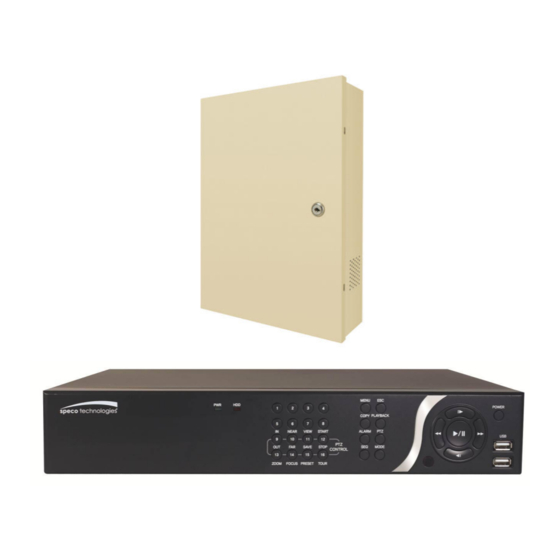
- Page 1 User Guide (Ver. 2.2) Models: Desktop - N4/8/16NS, N4/8/16NSP, N16NSF Wall Mount - N4/8/16WNS, N4/8/16WNSP 4/8/16 Channel Network Video Recorder About This User’s Guide Before operating the unit, please read this user’s guide thoroughly and retain it for future reference.
-
Page 2: Explanation Of Graphical Symbols
Cautions Explanation of Graphical Symbols This symbol indicates the presence of important operating and maintenance (servicing) instructions in the literature accompanying the product. This symbol indicates the presence of “dangerous voltage” within the product’s enclosure that may be of sufficient magnitude to constitute a risk of electric shock, property damage, personal injury, or death. - Page 3 These precautions must be followed for safety reasons Warning Do not use if the unit emits smoke. Do not disassemble the unit. Do not place any heavy or sharp objects on the unit. Do not place on uneven surface. ...
-
Page 4: Product Components
Product Components Please make sure the following components are included as specified below. Desktop: N4NS / N8NS / N16NS N4NSP / N8NSP / N16NSP N16NSF Wall Mount: N4WNS/ N8WNS / N16WNS N4WNSP / N8WNSP / N16WNSP Remote Control Battery 1.5V (AAA x 2 EA) Quick Setup Guide &... - Page 5 Specifications for NS/NSP MODEL N4NS N8NS N16NS N4NSP N8NSP N16NSP IP Cameras Input Max Bit Rate 20Mbps 40Mbps 20Mbps 40Mbps Video Resolution Max. 1920x1080 Main Monitor VGA and HDMI Output Sub Monitor CVBS (BNC) IP Cam Audio Input RCA Input...
- Page 6 User I/F Input Method Front Buttons, IR, Mouse, Keyboard Controller Dynamic DNS Yes (Free DDNS) Digital Zoom DLS (Day Light Savings) NTP (Network Time Protocol) Features S.M.A.R.T. Internal Beep Multi-Language e-mail Notification 3G Mobile iPad / iPhone / Android Network Web Viewer Windows (IE, Chrome, Firefox, Safari), MAC(TBD) Access...
- Page 7 Specifications for N16NSF MODEL N16NSF IP Cameras Input Max Bit Rate 40Mbps Video Resolution Max. 1920x1080 Main Monitor VGA and HDMI Output Sub Monitor CVBS (BNC) IP Cam Audio 16 (#1~#4: RCA, #5~#16: Audio Cable) Input RCA Input Audio Output RCA Output Audio Codec G.711...
- Page 8 Dynamic DNS Yes (Free DDNS) Digital Zoom DLS (Day Light Savings) NTP (Network Time Protocol) Features S.M.A.R.T. Internal Beep Multi-Language e-mail Notification 3G Mobile iPad / iPhone / Android Network Web Viewer Windows (IE, Chrome, Firefox, Safari), MAC(TBD) Access PC Client Single / Multi Client and CMS (64 channels) Remote Setup and Upgrade Power...
-
Page 9: Table Of Contents
Table of Contents Main Features ..........................12 Initial Boot-up Process ......................... 13 2-1. Initial Boot up and Basic Time Setup ..................13 2-2. Setting up Daylight Savings Time ..................14 2-3. Setting NTP (Network Time Protocol) ..................14 2-4. EZ SETUP ..........................17 2-5. - Page 10 5-3. SEARCH Screen ........................60 5-3-1. EZSearch ........................61 5-3-2. Time Line Search ......................62 5-3-3. Event Search ........................ 62 5-3-4. Go To First Time ......................63 5-3-5. Go To Last Time ......................63 5-3-6. Go To Specific Time ...................... 63 5-3-7.
- Page 11 7-7-6. Network ........................86 7-7-7. User Management ......................87 7-7-8. Storage ......................... 88 7-7-9. Remote Upgrade ......................88 7-7-10. Information ......................... 88 7-8. Operation ..........................89 7-8-1. Addition, Delete, and Modify of NS Sites ............... 89 7-8-2. Connect and Disconnect ....................91 7-8-3.
-
Page 12: Main Features
1. Main Features Automatic IP Camera Detection and connection (Plug & Play) Easy Record, Copy and Setup Easy Search by Thumbnail Preview Easy Copy Easy Network Easy IP Camera Setup NOTE: Under federal law, The Fourth Amendment to the U.S. -
Page 13: Initial Boot-Up Process
2. Initial Boot-up Process 2-1. Initial Boot up and Basic Time Setup 1. During the first boot up, the following logo will be displayed. 2. After the logo, select the language and set date and time as specified below. -
Page 14: Setting Up Daylight Savings Time
2-2. Setting up Daylight Savings Time To enable Daylight Saving feature/NTP synchronization, take the following steps. 1. Enter the SETUP mode. The default Username is “ADMIN” and Password is “1111”. 2. Go to SETUP > SYSTEM > DATE & TIME SETUP 3. - Page 15 2. Select the proper TIME ZONE time. Table2.3.1. GMT Time Zone State Standard Time Daylight-Saving Time Alabama GMT-6 GMT-5 Alaska GMT-9 GMT-8 Alaska (Aleutian Islands) GMT-10 Arizona GMT-7 Arizona (Navajo) GMT-7 GMT-6 Arkansas GMT-6 GMT-5 California GMT-8 GMT-7 Colorado GMT-7 GMT-6 Connecticut GMT-5...
- Page 16 Michigan (W) GMT-6 GMT-5 Minnesota GMT-6 GMT-5 Mississippi GMT-6 GMT-5 Missouri GMT-6 GMT-5 Montana GMT-7 GMT-6 Nebraska GMT-6 GMT-5 Nebraska (W) GMT-7 GMT-6 Nevada GMT-8 GMT-7 New Hampshire GMT-5 GMT-4 New Jersey GMT-5 GMT-4 New Mexico GMT-7 GMT-6 New York GMT-5 GMT-4 North Carolina...
-
Page 17: Ez Setup
2-4. EZ SETUP Quick installation Menu for NS and IP Camera Easy installation(Right-Click on the Main Screen) Figure 2.4. EZ Setup Screen 2.4.1. Setup DATE & TIME, IP CAMERA configurations. Figure 2.4.1. EZ CAMERA Setup Procedure ① Select EZ Camera for Date/Time and Camera Setup, Click NEXT to proceed. ②... - Page 18 If necessary, click on Preview to Preview the camera, or Setup to change camera settings. 2.4.2. EZ NETWORK Figure 2.4.2. EZ NETWORK Setup Procedure ① Select EZ Network for Network Setup. ② It begins to test and detect the network environment automatically. ③...
-
Page 19: Poe Port Setup
2-5. PoE Port SETUP Figure 2.5.1 PoE Port (N4NSP / N8NSP & N16NSP) Figure 2.5.2 PoE Port (N16NSF) 2.5.1 Connecting the Camera(NSP Model) Figure 2.5.1.1 IP Camera Connection Diagram (N8NSP) - Page 20 Private Network - IP Cameras only Clients IP Cameras Switch Hub Internet Router Figure 2.5.1.2 IP Camera Connection Diagram (N16NSP) Clients able 2.5.1. Factory Default of the IP Camera The following IP Camera settings are recommended for optimal connection with the NS Series Setup Items Default Description...
- Page 21 Figure 2.5.1.2. Incorrect connection with the PoE Ports With the NSP Models, it is prohibited to connect a router to the POE Ports to connect the IP Camera, the NSP will not be able to find and connect to the camera. The LAN Port can be connected to a router, but not the PoE Ports.
-
Page 22: Non Poe Port Setup
2-6 . Non PoE Port SETUP 2.6.1 Connecting the Camera (Non - PoE Model) Figure 2.6.1.1. Proper connection example of the NS (Non PoE Switch). The NS Series features a "Plug and Play" function (on board PoE Switch not included). ... -
Page 23: Dual Streaming
① Click the mouse right button ② Select “IP Camera Setup”. ③ Select Channel Number. ④ It launches the camera’s web setup page. In order for the web pages to launch from the “IP Camera Setup” menu when accessed from the WAN, Ports 59011 to 59254 on the router must be port forwarded to the NVR. -
Page 24: Front And Rear Panels
3. Front and Rear Panels 3-1. Desktop Front Panel Figure 3.1.1. Desktop NS Front panel Table 3.1.1. Front LED and Port of NS Name Description POWER LED light is on when power is applied to the system. LED light is on when the system is recording video data. USB Port This USB port for archiving footage into a USB device. -
Page 25: Connectors
3-2. Connectors Do not power this system on before all the connections are completed. Make sure all the connections are properly secured. Faulty connection may result in the system being damaged. [ N4/8/16NS ] [ N4NSP ] [ N8/16NSP ] Figure 3.2.1. - Page 26 ⑪ E-SATA: 1 External SATA Terminal ⑫ USB PORT: Connector for USB Mouse or USB flash memory. ⑬ ETHERNET PORT1: RJ-45 Connector for LAN Connection, used for Internet Connection ⑭ SENSOR IN, ALARM OUT, RS-485: 4 sensor inputs, 1 alarm output and RS-485 for PTZ ⑮...
-
Page 27: Remote Control
3-3. Remote Control ① ID: Used to set up the remote control ID. ② REC: To enable or disable manual recording mode. ③ SEARCH: Goes to SEARCH menu for playback options. ④ F/ADV: During Playback – Moves the playback forward by 60 seconds. ... -
Page 28: Setting Up The Ns
4. Setting up the NS The following sections detail the initial setup of the NS. Menu screen will close if user input is not received within 5 minutes. 4-0. Setup – Main Live Screen To enter the setup menu, right click on the mouse and select setup from the submenu or press the setup button on the remote control. -
Page 29: Setup - Ip Camera
4-1. Setup – IP CAMERA Press the SETUP button and enter the password. The IP Camera setup menu is displayed below. Figure 4.1.1. IP Camera mode setup screen Table 4.1.1. Menu items in IP CAMERA mode setup Item Description CHANNEL To manually connect each camera, click on the to get this window: Under the column labeled Type, Select IP Camera Manufacturer. - Page 30 IP: Enter the address of IP camera to connect, or select from scanned list. PORT: Enter the port number of IP camera to connect WEB PORT: Enter the web port number of IP camera to connect OTHERS: Change the IP camera setting. Double click the empty box and then Log-In box will be pop-up.
-
Page 31: Scan Menu
④ IP cameras using ONVIF protocol require ID, Password and Profile to be correctly entered for proper operation. ⑤ SPECO protocols only require ID and Password to be correctly entered for proper operation. IP cameras using ONVIF protocol can have their Video, Network and System settings accessed and updated using the ONVIF setup menu. -
Page 32: Onvif Setup Menu
4-1-2. ONVIF SETUP Menu Figure 4.1.2 IP CAMERA Setup Screen (ONVIF) The NS Series can search for IP Cameras that are conformant to ONVIF (Open Network Video Interface Forum). In order to search for ONVIF Cameras, the field associated with VENDOR has to be set to ONVIF. Click on the Box associated with SCAN to scan the networks for ONVIF Conformance cameras. - Page 33 ④ Double click the listed profile to apply. ⑤ Enter ID and PASSWORD of IP CAM. Registration is .completed. Figure 4.1.6 ONVIF Setup Window Under ONVIF Setup, the following can be viewed and changed: VIDEO, NETWORK, SYSTEM settings. Menu Item Description VIDEO Video, Encoder to view and change to audio settings.
-
Page 34: Setup - System
4-2. Setup – SYSTEM In the SETUP menu, select the SYSTEM tab. Then, the SYSTEM menu is displayed as pictured below. Navigate through the menu items or change the settings using the mouse or the remote control. Figure 4.2.1. SYSTEM Setup Screen Table 4.2.1. - Page 35 - Select the GMT AREA using the mouse or the remote control. - Set the time difference with the standard time using the mouse or the button. OTHERS: If the time zone is neither USA nor EU, set the date and time of the daylight saving period.
- Page 36 SEND EMAIL SERVER TYPE: Select GMAIL, HOTMAIL, AOL, YAHOO or MANUAL) MAIL SERVER: Enter the appropriate mail server information. MAIL PORT: Assign Mail Port number. SECURE OPTION: Select the secure mail server connection method. (SSL or TLS) ID: Enter the appropriate mail server ID. PASSWORD: Enter the appropriate mail server PASSWORD MAIL TO: Enter the appropriate email address to enable sending e-mail reports using a virtual keyboard.
-
Page 37: Setup - Record Mode
4-3. Setup – RECORD Mode In the SETUP menu, select the RECORD tab. Then, the RECORD menu is displayed as pictured below. Navigate through the menu items or change the settings using the mouse or the remote control. Figure 4.3.1. RECORD Setup Screen Table 4.3.1. - Page 38 SENSOR Select the sensor setting for the selected channel. RECORDING PRE RECORD Enable/disable pre-event recording. Pre-event recording time is up to 20 minutes. POST EVENT Set the post event recording time duration for the specified channel. RECORD (10~30 seconds) AUDIO Enable/disable audio recording for the specified channel.
-
Page 39: Recording Schedules
3-1. Recording Schedules To setup a recording schedule, select SCHEDULE in the RECORD menu. Navigate through the menu items or change the settings using the mouse or the remote control. Select CHANNEL > select NONE, CONTINUOUS or MOTION > Highlight area To copy a schedule to a different channel, select the channel from the COPY SCHEDULE menu. -
Page 40: Setup - Device Mode
4-4. Setup – DEVICE Mode In the SETUP menu, select the DEVICE tab. Then, the device menu is displayed as pictured below. Navigate through the menu items or change the settings using the mouse or the remote control. Figure 4.4.1. DEVICE Setup Screen Table 4.4.1. - Page 41 MOTION Select either Full Zone or Partial Zone for motion detection. ZONE MOTION Set the motion sensitivity for the selected channel. SENSITIVITY Control the motion sensitivity from 1 to 9. (9 – Highest sensitivity, 1 – Lowest sensitivity) KEY TONE Enable/disable key tone from front panel usage.
-
Page 42: Digital Deterrent
4-4-1. Digital Deterrent Trigger audio message via motion detection or sensor. Figure 4.4.2. Digital Deterrent setup screen Table 4.4.2. Item for Digital Deterrent Setup Screen Item Description IMPORT FROM USB Import up to 8 sound files from USB. EXPORT TO USB Export the sound file to USB RECORD Select a channel and set up the date and the duration. -
Page 43: Keyboard Controller & Ptz Setup
4-4-2. Keyboard Controller & PTZ Setup To control the PTZ functions of the camera, connect the PTZ controller to the RS-485 port on the back of the chassis with CAT5 (or equivalent) cable. ① Connect the RS-485 cables of PTZ camera to the RS-485 port on the rear panel. Figure 4.4.2.1. -
Page 44: Motion Zone Setup
4-4-3. Motion Zone Setup Select MOTION ZONE using the mouse or the remote control and select either PARTIAL ZONE or FULL ZONE using the mouse control. The default value is FULL ZONE. If FULL ZONE is selected, the motion zone grid screen is not displayed. Only set the level of sensitivity for MOTION SENSITIVITY. -
Page 45: Setup - Display Mode
4-5. Setup – DISPLAY Mode In the SETUP menu, select the DISPLAY tab. Then, the DISPLAY menu is displayed as pictured below. Navigate through the menu items or change the settings using the mouse or the remote control. To return to the previous setup menu screen, press the ESC button. -
Page 46: Setup - Network Mode
4-6. Setup – NETWORK Mode Select the NETWORK tab. Then, the network menu is displayed as pictured below. Navigate through the menu items or change the settings using the mouse or the remote control. Figure 4.6.1. NETWORK Setup Screen Table 4.6.1. Menu Items in NETWORK Setup Screen Item Description NETWORK TYPE... -
Page 47: Network Types
4-6-1. Network Types 4-6-1-1. DHCP An IP address is automatically assigned by the DHCP server, which automatically assigns the IP address and other parameters to new devices. 4-6-1-2. STATIC IP address, Subnet Mask, Gateway, and DNS are manually assigned by the user. ... -
Page 48: Network Port And Web Port
4-6-3. Network Port and Web Port Connecting NS/NSP through a common IP sharing device, each NS must be assigned a unique TCP port number for access from outside the LAN. This port number is displayed on NETWORK>NETWORK PORT Setup MENU. NOTE: If you access the NS only within the same LAN, the TCP port number does not need to be changed. -
Page 49: Setup - User Management Mode
4-7. Setup – USER MANAGEMENT Mode In the SETUP menu, select the USER MANAGEMENT tab. Then, the USER MANAGEMENT menu is displayed as pictured below. Navigate through the menu items or change the settings using the mouse or the remote control. Figure 4.7.1. - Page 50 ADMIN, USER1, USER2, USER3: Selected Checkbox: The user can access the function. Blank Checkbox: The user can not access the function. USER NAME Change the name of USER1, USER2 and USER3. Click “ENTER” after naming. SETUP PASSWORD Passwords can be changed for ADMIN, USER1, USER2 and USER3. Select USER PASSWORD using the mouse or the remote control.
-
Page 51: Setup - Storage Mode
4-8. Setup – STORAGE Mode In the SETUP menu, select the STORAGE tab. Then, the STORAGE menu is displayed as pictured below. Navigate through the menu items or change the settings using the mouse or the remote control. Figure 4.8.1. STORAGE Setup Screen Table 4.8.1. - Page 52 RECORDING Enable recording limit : The amount of data recorded in HDD will be limited to the most recent number of days as set by “RECORDING LIMIT DAYS”. LIMIT Disable recording limit : When OVERWRITE is ON, DVR will continue to record when HDD is full and overwrite older data.
-
Page 53: Setup - Config Mode
4-9. Setup - CONFIG Mode In the SETUP menu, select the CONFIG tab. Then, the configuration menu is displayed as pictured below. Navigate through the menu items or change the settings using the mouse or the remote control. Figure 4.9.1. CONFIGURATION Setup Screen Table 4.9.1. -
Page 54: Firmware Upgrade
1. Create a new folder named “upgrade” in the USB flash drive root directory. 2. Create sub-folder for each model under “upgrade” folder and copy each firmware. “n4ns” for N4NS and N4NSP: “main_n4ns_speco_*.*.*_201****” “n8ns” for N8NS and N8NSP: “main_n8ns_speco_*.*.*_201****”... -
Page 55: Live, Search And Playback
5. Live, Search and Playback 5-1. Live View In the Live screen, video inputs from the cameras are displayed as they are configured in the Display Setup screen. Various On-Screen Display (OSD) symbols, which indicate the status of the NS, are described in Table 5.1.1. - Page 56 Indicates that sequencing mode is enabled. Displays the current date and time. Remote control ID display. If a remote ID is not set, the message “ALL” is RC: ALL displayed. Displays the amount of recording on the hard disk from 0-99%. Indicates that HDD is recycled.
- Page 57 SUPER EZ COPY Select this option to start EZ Copy Wizard. ENABLE MANUAL Manual Record button. Click this button to enable manual RECORD recording. Instantly playback 10 to 60 seconds of recorded data. INSTANT PLAYBACK Recommended to be used with record mode set to CONTINUOUS. ADVANCED MENU EZ SETUP Select this option to start EZ Setup Wizard.
- Page 58 EXPORT HELP Displays window with instructions for exporting video. SYSTEM Locks the system from unauthorized user access. LOCK SYSTEM Select this option to shutdown system. SHUTDOWN...
-
Page 59: Ptz Control
5-1-1. PTZ Control Table 5.1.3. Menu Items in PTZ Control Window Item Description INITIALIZE Initialize the PTZ settings of the selected camera Select PAN/TILT using the ▲▼◀ and ▶button, then PAN/TILT press SEL. Adjust the tilt (UP/DOWN) & pan (LEFT/RIGHT) position using the ▲▼◀and ▶buttons. -
Page 60: Digital Zoom In Live And Playback Screen
5-2. Digital Zoom in Live and Playback Screen NS series supports Digital Zoom feature during live and playback mode. 1. Double click the target channel. 2. Click the left button of the mouse and drag to make rectangular shape. 5-3. SEARCH Screen To enter the search screen menu, select SEARCH menu on the screen using the mouse or press SEARCH icon on live screen. -
Page 61: Ezsearch
5-3-1. EZSearch The EZSearch window is used to find stored video with ease using the thumb nail playback screen. Figure 5.3.2. Calendar Screen Figure 5.3.3. Channel Selection Screen Figure 5.3.4. 24 Hourly Thumbnail Screen Figure 5.3.5. Minute Thumbnail Screen Figure 5.3.6. Play Mode Screen 1. -
Page 62: Time Line Search
5-3-2. Time Line Search The CALENDAR Search window is used to find the stored video by using the time line bar. Figure 5.3.7. Calendar Screen Figure 5.3.8. Time-Line Search Screen When the Timeline menu is selected, the user can see a calendar, which displays recorded dates with highlights. -
Page 63: Go To First Time
Figure 5.3.10. Event Search Screen 5-3-4. Go To First Time User can access from the oldest recorded data on the NS hard drive by selecting GO TO FIRST TIME on the SEARCH window. Press the PREV to return to the SEARCH window. 5-3-5. -
Page 64: Log List
5-3-8. Log List You can access the LOG list search screen by selecting LOG on the SEARCH window. Figure 5.3.12. Log List Screen When the Log menu is selected, the user can see a calendar, which has a log data. Select a specific date and press NEXT button, and then the log data will be displayed. - Page 65 Table 5.4.1. Button Functions in PLAY Mode Button Description 2x, 4x, 8x,16x, 32x speeds at 2x2 screen display mode. 2x, 4x, 8x,16x speeds at 3x3 screen display mode. 2x, 4x, 8x speeds at the 4x4 screen display mode. ...
-
Page 66: Back Up
6. Back Up 6-1. Still Image Backup onto USB Flash Drive Still images can be captured and archived onto a USB flash drive or an USB external hard drive in live mode or while playing back recorded video. 1. Select a specific channel, which wants to backup on live screen. 2. - Page 67 2. Select USB STICK DRIVE (Flash Drive) to back up less than an hour. Select USB HDD (Large Backup) to back up from 1 hour to 24 hours. 3. Once you select the channel and duration, the system will start to archive the data to the USB drive. 4.
-
Page 68: Ezcopy: Video Backup Onto Usb Flash Drive During Playback
6-2. EZCopy: Video Backup onto USB Flash Drive during playback Using EZCopy feature, Video can be easily archived onto the USB flash drive or a hard drive. In playback mode, press the EZCOPY button to launch the backup function. 1. Press EZCOPY button on the selected channel or all channels. 2. -
Page 69: Transferring Still Images Or Video From The Archive List
6-3. Transferring Still Images or Video from the ARCHIVE List The stored data in the hard drive can be found in the ARCHIVE list in the SEARCH window. User can back up still images or video into the storage device from the ARCHIVE list. 1. -
Page 70: Nsf Format
2. Otherwise, the video and time stamp over video can’t be properly playback and displayed on Window Media Player™. Timestamp On AVI. The subtitle is embedded to the video clip file. The subtitle is embedded to the AVI file. To display a subtitle, user should install a special filter called “UMSDecoderFilter”. -
Page 71: Network Access Using The Multi-Sites Network Viewer
7. Network Access Using the Multi-Sites Network Viewer 7-1. Overview The SpecoTech Multi Client is a multiple site monitoring client software with; video, audio, and alarm signals from the NS over the network. The SpecoTech Multi Client does not limit the number of NS units to register. The program displays up to 16 NS units and supports dual monitors. -
Page 72: Installation Of The Program
7-3. Installation of the Program 1. Insert the provided CD in the CD drive and double-click “SpecoTech Multi Client (XXXX).exe” 2. Select a destination folder and click “Next”. 3. Select the program folder and click “Next”. 4. The installation status screen is displayed. 5. -
Page 73: Live Window
7-4. Live Window When installation is completed, double click the “SpecoTech Multi Client” icon on your desktop to start the program. 7-4-1. Main User Interface 7-4-2. Control Buttons Button Description Click this icon to run a playback window to search and play videos that are recorded in the local PC. -
Page 74: Search And Playback Window
Click this icon to setup configuration of MULTI CLIENT. SETUP Click this icon to capture a still image. CAPTURE Opens list of events logged by Multi Client. EVENT LIST Click this icon to play/pause live video. PAUSE Click this icon to turn on/off alarm outputs. ALARM ON Enable or disable recording of live video to local disk, which has set in RECORD ON... -
Page 75: Main Control Panel
7-5-2. Main Control Panel Button Description Click this icon to run a playback window to search and play videos that LOCAL PLAYBACK are recorded in the local PC. Click this icon to run a playback window to search and play videos that REMOTE PLAYBACK are recorded in the remote NS. -
Page 76: Setup Of Specotech Multi Client
To select the channel to playback. The calendar shows dates with recorded video in color. To display the recorded data of selected channel or all channels on a time line scale. To change a timeline scale from 24 hours to 60 minutes. The timeline shows recorded data in color on the bar. -
Page 77: Event
7-6-2. Event Event log can be archived and searched. Event Log: Specify the location to save event logs and select event to archive. -
Page 78: Record
Event Search: Event log can be searched from the selected time. 7-6-3. Record Record Setup: You can set the recording conditions as the following; Always, Event, or Auto record. And you can also select target NS/NSs and channel/channels. When you set the recording condition to event, you can set event for motion or alarm with duration. -
Page 79: Display
Record Local Storage Setup: You can select the local disk to record and the amount of disk space you want to allow the program to use for recording. You can also select the option to overwrite data or stop recording when the maximum amount of disk space is full. 7-6-4. -
Page 80: Language
7-6-5. Language English, French and Spanish is selectable. 7-6-6. About “About” provides network client version information. -
Page 81: Remote Setup
7-7. Remote Setup The menu settings for the NS unit can be set over network. Put the cursor of the mouse on the channel, which is connected to the site and right click on the mouse to open the submenu. Then the following window is displayed as below. Select the REMOTE SETUP. Then the setup window is displayed. -
Page 82: Ip Camera
7-7-1. IP Camera Select IP Camera to set system and time settings 7-7-2. System Select System to set system and time settings. DATE DISPLAY FORMAT: Select the date display format. TIME DISPLAY FORMAT: Select the time display format. ... - Page 83 CLIENT ACCCESS: Enable/Disable remote access through network client software. NTP SETUP: Sets whether to synchronize the time using NTP server or not. o Primary SNTP Server: Input the NTP primary server address. o Secondary SNTP Server: Input the NTP secondary server address. o Time Zone: Select the time zone.
-
Page 84: Record
HDD BAD SECTOR HDD ALMOST FULL o VIDEO CLIP SETUP: Setting the duration for pre and post recording. o EVENTS AND NOTIFICATION HEALTH CHECK / RESTART / SHUTDOWN / PANIC RECORD: Enable Email Notification in the event a problem occurs with the NS. ALARM-IN : Enable Email Notification when the camera detects sensor MOTION DETECTION : Enable Email Notification when the camera detects motion NO CONNECTION: Enable Email, Beep and Alarm output Notification when the... -
Page 85: Device
7-7-4. Device Select Device to set device settings of the NS ALARM OUT: Set the sensor, motion, and video loss for triggering alarm relay. HDD Error and Video Loss can be set for triggering a beeping sound The following settings can be changed to trigger an alarm output. o ALARM DURATION ... -
Page 86: Display
REMOTE CONTROLLER ID: Sets an ID number of which remote control to receive commands. SENSOR: Select the type of sensor. IEEE 802.3af PSE Status: Table showing the status of all PoE devices connected to the NSP. 7-7-5. Display Select the DISPLAY tab to set the DISPLAY conditions. -
Page 87: User Management
o DHCP: The address setting mode is automatic. DDNS: Set whether to use DDNS service or not o HOST NAME: A llows the user to setup a domain name manually o SUMBIT/UPDATE: Select ON to submit the settings o ezDDNS: Enable ezDDNS to register the host name automatically ... -
Page 88: Storage
7-7-8. Storage Select Storage to configure recording settings such as overwriting the hard disk and the setting a storage period for the recording data. OVERWRITE: Select on to continue recording by overwriting when the hard disk becomes full. RECORD LIMIT: Sets whether to limit or not the recording data storage period. -
Page 89: Operation
7-8. Operation 7-8-1. Addition, Delete, and Modify of NS Sites 7-8-1-1. Addition of Sites 1. Click SITE ADDITION button. And then the following window will be displayed as below. o Site Name: Input a name that properly describes a site. o IP Address: Input IP address (Public IP address of a router that NS is connected.) or Domain name o Port Number: Default Port Number is “5445”. - Page 90 7-8-1-3. Modify of Sites 1. Select the site/sites to modify from the directory window. 2. Click NET FINDER button. And then the following window will be displayed as below. 3. Click MODIFY button. And then the modified information is displayed as below.
-
Page 91: Connect And Disconnect
7-8-2. Connect and Disconnect 7-8-2-1. Connect 1. Select site/sites to connect from the directory window. 2. Click CONNECT button, and then site/sites displays/display as connected. 7-8-2-2. Disconnect 1. Select site/sites to disconnect from the directory window. 2. Click DISCONNECT button, and then selected site/sites disconnected. -
Page 92: Still-Image Capture During Live
7-8-3. Still-image Capture During Live 1. Double-click a channel to capture from the display screen. (Otherwise all channels will be captured.). 2. Click CAPTURE button. And then a Capture window will be displayed as below. 3. Set Save Path, File Name, and File Format. And then click OK button. 4. - Page 93 3. Select Disk and set the values. 4. Click RECORD ON button. And the color of button is changed. 5. Live video data is recorded as set in Record and Disk setup. These video data can be searched and play-backed with Local Playback.
-
Page 94: Local Playback And Remote Playback
7-8-5. Local Playback and Remote Playback 7-8-5-1. Playback of Recorded Video on a Local PC 1. Click LOCAL PLAYBACK. And then Playback Window will be displayed over the Live Window. 2. Select site/sites to connect from the directory window. 3. Click CONNECT button. - Page 95 7-8-5-2. Playback of Recorded Video on Remote NS 1. Click REMOTE PLAYBACK. And then Playback Window will be displayed over the Live Window. 2. Select the site to connect from the directory window. 3. Click CONNECT. And then Green bar displays on Search calendar and timeline scale window.
-
Page 96: Avi Backup During Playback
7-8-6. AVI Backup during Playback You can back up the recorded videos in AVI format during playback. 1. Double-click the target channel to backup. 2. Select the beginning time by using the search calendar and timeline scale bar. 3. Click EZCOPY START button on the timeline scale to select the beginning point of the backup. - Page 97 7. AVI video data is recorded as set in AVI Backup window. AVI format video can be played back by using Window Media Player™ or other media player that is compatible with AVI format video.
-
Page 98: Network Access Using The Web-Browser Viewer
8. Network Access Using the Web-Browser Viewer The NS provides a live remote monitoring feature by web-browser viewer. (NOTE: Web-Brower is only available for Internet Explorer) 1. Check the IP address of the NS from SETUP>SYSTEM>DESCRIPTION>IP ADDRESS or 2. Input the IP address or Domain name address that you pre-registered. 3. - Page 99 Site Name: Input a name that properly describes a site. IP Address: Input IP address (Public IP address of a router that NS is connected.) or Domain name Port Number: Default Port Number is “5445”. ID: Input ID of NS. Default ID is “admin”. ...
-
Page 100: Network Access Using The Smart Phone Viewer
2. Search “Speco Player” in the App Store. Notice SPECO Player is for the NS, NSL, VS, HS, DS, RS and HD series DVRs. SPECO VIEWER is not compatible with the T Series DVR’s (TH, TN or TL) or the PC Series 9-1-1. -
Page 101: 9-1-2.Ptz Control
4. The app will display the selected channel(s). Double tap the channel screen to switch 1 channel display to 4, 8, 10, 16 channels split display depending on the DVR. 5. To select the display mode(1, 4, 9, 10 or 16 split display), tap the arrow menus button 6. -
Page 102: Playback
9-1-3. Playback 1. Select Mode as ‘Playback’ and click ‘CONNECT’ button. Then select Date & Time and click PLAY button. 2. The app will display the selected channel(s). Double tap the channel screen to switch 1 channel display to 4, 8, 10, 16 channels split display depending on the DVR. -
Page 103: App Viewer For Android Phone
T Series NS’s (TH, TN or TL) or the PC Series. 9-2-1. Live 1. Open the installed “Speco Player” App and select the Live Preview. Then click the menu button of the phone to add a remote device. -
Page 104: Playback
9-2-2. Playback 1. Select the registered device and select PLAYBACK and select up to 4 channels or ALL CHANNELS to search. Then click START button. As soon as setting the date and time to search, the app will start the playback. 2. -
Page 105: Appendix: Network Connection - Lan
APPENDIX: Network Connection - LAN 1. Install the network client software from the supplied CD. 2. Check the IP address from SETUP > SYSTEM > DESCRIPTION or SETUP > NETWORK of NS. 3. Run the network client software. - Page 106 4. Input Site Name, Site Address (IP address), Port Number, and Password on the connect window. Site Name: Input a name that properly describes a site. IP Address: Input IP address Port Number: Default Port Number is “5445”. ...
-
Page 107: Appendix: Network Connection - Internet And Ddns
2. Go to SETUP>NETWORK>DDNS>HOST NAME. Manually enter a domain name using the virtual keyboard and click ENTER button. 3. When a manual host name is completed, Go to SETUP>NETWORK>DDNS>SUBMIT/UPDATE and select ON to submit the settings on the SPECO DDNS. Once the setting is completed, the DDNS address will be: http://hostname.ddns.specoddns.net For example, if you enter the host name as “NS”, then the address will be:... - Page 108 4. When DDNS setting is done, click the APPLY button. Otherwise DDNS setting will not be applied. 5. When you exit SETUP menu, DDNS NOTIFIY window will pop up. 6. DDNS registration status can be checked from SYSTEM INFORMATION or SETUP>SYSTEM>DESCRIPTION>DDNS STATUS 7.
- Page 109 10. Input Site Name, Site Address (IP address), Port No., and Password on the connect window. Site Name: Input a name that properly describes a site. IP Address: Domain name or Public IP address of a router that NS is connected. ...
-
Page 110: Appendix: E-Sata Connection
Please read the following instructions before using the E-SATA port. Failure to do so may cause serious damage to the recorded video. SPECO is not responsible for data loss caused by improper usage. Use ONLY a new HDD or a HDD that is approved for the unit.