Table of Contents
Advertisement
Advertisement
Chapters
Table of Contents

Related Manuals for Asus B85M-G


Summary of Contents for Asus B85M-G
- Page 1 B85M-G E9884_B85M-G_v4_Manual.indb 1 2014/11/4 11:09:45...
- Page 2 Product warranty or service will not be extended if: (1) the product is repaired, modified or altered, unless such repair, modification of alteration is authorized in writing by ASUS; or (2) the serial number of the product is defaced or missing.
-
Page 3: Table Of Contents
Contents Safety information ...................... iv About this guide ......................iv Package contents ....................... vi B85M-G specifications summary ................vi Product introduction Before you proceed ................... 1-1 Motherboard overview ................1-1 Central Processing Unit (CPU) ..............1-3 System memory ..................1-7 Expansion slots .................. -
Page 4: Safety Information
Safety information Electrical safety • To prevent electrical shock hazard, disconnect the power cable from the electrical outlet before relocating the system. • When adding or removing devices to or from the system, ensure that the power cables for the devices are unplugged before the signal cables are connected. If possible, disconnect all power cables from the existing system before you add a device. -
Page 5: Conventions Used In This Guide
Refer to the following sources for additional information and for product and software updates. ASUS websites The ASUS website provides updated information on ASUS hardware and software products. Refer to the ASUS contact information. Optional documentation Your product package may include optional documentation, such as warranty flyers, that may have been added by your dealer. -
Page 6: Package Contents
4 x DIMM, max. 32GB, DDR3 1600 / 1333 / 1066 MHz, non-ECC, un- buffered memory Dual-channel memory architecture * Refer to www.asus.com for the latest Memory QVL (Qualified Vendors List). ® ** Due to Intel chipset limitation, the DDR3 1600MHz and higher memory modules on XMP mode will run at the maximum transfer rate of DDR3 1600MHz. - Page 7 - ASUS ESD Guards - Enhanced ESD protection 2.5x longer - ASUS High-Quality 5K-Hour Solid Capacitors - lifespan with excellent durability - ASUS Stainless Steel Back I/O - 3x More durable corrosion- resistant coating ASUS EZ DIY: - ASUS CrashFree BIOS 3...
- Page 8 1 x 4-pin ATX 12V power connector BIOS features 64Mb Flash ROM, EFI BIOS, PnP, DMI v2.0, WfM2.0, SM BIOS v2.7, ACPI v2.0a, SLP 3.0, EUP-ready, Multi-language BIOS, ASUS EZ Flash 2, ASUS CrashFree BIOS 3 Manageability WOL by PME, WOR by PME, PXE...
-
Page 9: Product Introduction
1.2.2 Screw holes Place six screws into the holes indicated by circles to secure the motherboard to the chassis. Do not overtighten the screws! Doing so can damage the motherboard. ASUS B85M-G E9884_B85M-G_v4_Manual.indb 1 2014/11/4 11:09:46... -
Page 10: Motherboard Layout
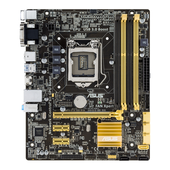
Place this side towards the rear of the chassis B85M-G 1.2.3 Motherboard layout 19.3cm(7.6in) KBMS CPU_FAN DIGI +VRM ATX12V USB910 USB3_56 HDMI 1442 CHA_FAN LAN_USB34 BATTERY AUDIO PCIEX16 B85M-G 8111G 64Mb BIOS PCIEX1_1 Super Intel ® PCIEX1_2 SPDIF_OUT SATA6G_4 CHASSIS... -
Page 11: Central Processing Unit (Cpu)
13. USB device wake-up (USBPWF) 1-11 14. LPT connector (26-1 pin LPT) 1-14 15. Chassis intrusion connector (4-1 pin CHASSIS) 1-20 16. Serial port connectors (10-1 pin COM) 1-15 17. Front panel audio connector (10-1 pin AAFP) 1-15 18. Digital audio connector (4-1 pin SPDIF_OUT) 1-19 Central Processing Unit (CPU) This motherboard comes with a surface mount LGA1150 socket designed for the Intel 4th ® generation Core™ i7 / Core™ i5 / Core™ i3, Pentium , Celeron processors. ® ® B85M-G B85M-G CPU socket LGA1150 ASUS B85M-G E9884_B85M-G_v4_Manual.indb 3 2014/11/4 11:09:46... -
Page 12: Installing The Cpu
Unplug all power cables before installing the CPU. • Upon purchase of the motherboard, ensure that the PnP cap is on the socket and the socket contacts are not bent. Contact your retailer immediately if the PnP cap is missing, or if you see any damage to the PnP cap/socket contacts/motherboard components. ASUS will shoulder the cost of repair only if the damage is shipment/ transit-related. • Keep the cap after installing the motherboard. ASUS will process Return Merchandise Authorization (RMA) requests only if the motherboard comes with the cap on the LGA1150 socket. • The product warranty does not cover damage to the socket contacts resulting from incorrect CPU installation/removal, or misplacement/loss/incorrect removal of the PnP cap. 1.3.1 Installing the CPU Chapter 1: Product introduction E9884_B85M-G_v4_Manual.indb 4 2014/11/4 11:09:46... -
Page 13: Cpu Heatsink And Fan Assembly Installation
1.3.2 CPU heatsink and fan assembly installation Apply the Thermal Interface Material to the CPU heatsink and CPU before you install the heatsink and fan if necessary. ASUS B85M-G E9884_B85M-G_v4_Manual.indb 5 2014/11/4 11:09:47... - Page 14 To install the CPU heatsink and fan assembly To uninstall the CPU heatsink and fan assembly Chapter 1: Product introduction E9884_B85M-G_v4_Manual.indb 6 2014/11/4 11:09:47...
-
Page 15: System Memory
System memory 1.4.1 Overview This motherboard comes with four Double Data Rate 3 (DDR3) Dual Inline Memory Module (DIMM) sockets. A DDR3 module has the same physical dimensions as a DDR2 DIMM but is notched differently to prevent installation on a DDR2 DIMM socket. DDR3 modules are developed for better performance with less power consumption. The figure illustrates the location of the DDR3 DIMM sockets: Channel Sockets Channel A DIMM_A1 & DIMM_A2 Channel B DIMM_B1 & DIMM_B2 B85M-G B85M-G 240-pin DDR3 DIMM sockets 1.4.2 Memory configurations You may install 1GB, 2GB, 4GB, and 8GB unbuffered non-ECC DDR3 DIMMs into the DIMM sockets. • You may install varying memory sizes in Channel A and Channel B. The system maps the total size of the lower-sized channel for the dual-channel configuration. Any excess memory from the higher-sized channel is then mapped for single-channel operation. • Due to Intel chipset limitation, DDR3 1600MHz and higher memory modules on XMP ® mode will run at the maximum transfer rate of DDR3 1600MHz. • Always install DIMMs with the same CAS latency. For optimal compatibility, we recommend that you install memory modules of the same version or date code (D/C) from the same vendor. Check with the retailer to get the correct memory modules. •... -
Page 16: Installing A Dimm
• The default memory operation frequency is dependent on its Serial Presence Detect (SPD), which is the standard way of accessing information from a memory module. Under the default state, some memory modules for overclocking may operate at a lower frequency than the vendor-marked value. To operate at the vendor-marked or at a higher frequency, refer to section 2.5 Ai Tweaker menu for manual memory frequency adjustment. • For system stability, use a more efficient memory cooling system to support a full memory load (4 DIMMs) or overclocking condition. • Visit the ASUS website at: www.asus.com for the latest QVL. 1.4.3 Installing a DIMM Chapter 1: Product introduction E9884_B85M-G_v4_Manual.indb 8 2014/11/4 11:09:48... -
Page 17: Expansion Slots
To install an expansion card: Before installing the expansion card, read the documentation that came with it and make the necessary hardware settings for the card. Remove the system unit cover (if your motherboard is already installed in a chassis). Remove the bracket opposite the slot that you intend to use. Keep the screw for later use. Align the card connector with the slot and press firmly until the card is completely seated on the slot. Secure the card to the chassis with the screw you removed earlier. Replace the system cover. 1.5.2 Configuring an expansion card After installing the expansion card, configure it by adjusting the software settings. Turn on the system and change the necessary BIOS settings, if any. See Chapter 2 for information on BIOS setup. Assign an IRQ to the card. Install the software drivers for the expansion card. When using PCI cards on shared slots, ensure that the drivers support “Share IRQ” or that the cards do not need IRQ assignments. Otherwise, conflicts will arise between the two PCI groups, making the system unstable and the card inoperable. ASUS B85M-G E9884_B85M-G_v4_Manual.indb 9 2014/11/4 11:09:48... -
Page 18: Headers And Jumpers
Headers and Jumpers Clear RTC RAM (2-pin CLRTC) This header allows you to clear the Real Time Clock (RTC) RAM in CMOS. You can clear the CMOS memory of date, time, and system setup parameters by erasing the CMOS RTC RAM data. The onboard button cell battery powers the RAM data in CMOS, which include system setup information such as system passwords. CLRTC +3V_BAT B85M-G PIN 1 B85M-G Clear RTC RAM To erase the RTC RAM: Turn OFF the computer and unplug the power cord. Use a metal object such as a screwdriver to short the two pins. Plug the power cord and turn ON the computer. Hold down the <Del> key during the boot process and enter BIOS setup to re- enter data. 1-10 Chapter 1: Product introduction E9884_B85M-G_v4_Manual.indb 10 2014/11/4 11:09:48... -
Page 19: Keyboard And Usb Device Wakeup (Kb_Usbpwb)
Keyboard and USB device wake-up (KB_USBPWB) Set this jumper to +5V to wake up the computer from S1 sleep mode (CPU stopped, DRAM refreshed, system running in low power mode) using the connected USB devices. Set to +5VSB to wake up from S3 and S4 sleep modes (no power to CPU, DRAM in slow refresh, power supply in reduced power mode). KB_USBPWB +5VSB B85M-G (Default) B85M-G Keyboard and USB device wake up • The USB device wake-up feature requires a power supply that can provide 500mA on the +5VSB lead for each USB port; otherwise, the system would not power up. • The total current consumed must NOT exceed the power supply capability (+5VSB) whether under normal condition or in sleep mode. USB device wake-up (USBPWF) This jumper allows you to enable or disable the USB device wake-up feature. When you set this jumper to pins 2-3 (+5VSB), you can wake up the computer by pressing a key on the USB keyboard or by clicking on the USB mouse. This feature requires an... -
Page 20: Connectors
Connectors 1.7.1 Rear panel connectors PS/2 mouse port (green). This port is for a PS/2 mouse. Video Graphics Adapter (VGA) port. This 15-pin port is for a VGA monitor or other VGA-compatible devices. LAN (RJ-45) port. This port allows Gigabit connection to a Local Area Network (LAN) through a network hub. LAN port LED indications Activity/Link LED Speed LED Speed Activity Link Status Description Status Description No link 10Mbps connection Orange Linked ORANGE 100Mbps connection Orange... - Page 21 • USB 3.0 devices can only be used for data storage. • We strongly recommend that you connect USB 3.0 devices to USB 3.0 ports for faster and better performance from your USB 3.0 devices. • Due to the design of the Intel 8 series chipset, all USB devices connected to the ® USB 2.0 and USB 3.0 ports are controlled by the xHCI controller. Some legacy USB devices must update their firmware for better compatibility. USB 2.0 ports 9 and 10. These two 4-pin Universal Serial Bus (USB) ports are for USB 2.0/1.1 devices. DVI-D port. This port is for any DVI-D compatible device. DVI-D can’t be converted to output RGB Signal to CRT and is not compatible with DVI-I. Intel display architecture design supports the following maximum supported pixel clocks (Pixel Clock = H total x V Total x Frame Rate (Screen refresh rate)): HDMI port: 300 MHz DVI port: 165 MHz VGA port: 180 MHz PS/2 keyboard port (purple). This port is for a PS/2 keyboard. ASUS B85M-G 1-13 E9884_B85M-G_v4_Manual.indb 13 2014/11/4 11:09:49...
-
Page 22: Atx Power Connectors (24-Pin Eatxpwr, 4-Pin Atx12V)
-5 Volts Power OK PIN 1 +5 Volts +5 Volts PSON# B85M-G +3 Volts -12 Volts +3 Volts +3 Volts PIN 1 B85M-G ATX power connectors • We recommend that you use an ATX 12V Specification 2.0-compliant power supply unit (PSU) with a minimum of 300W power rating. This PSU type has 24-pin and 4-pin power plugs. • DO NOT forget to connect the 4-pin ATX +12V power plug. Otherwise, the system will not boot up. • We recommend that you use a PSU with higher power output when configuring a system with more power-consuming devices or when you intend to install additional devices. The system may become unstable or may not boot up if the power is inadequate. -
Page 23: Serial Port Connectors (10-1 Pin Com)
This connector is for a chassis-mounted front panel audio I/O module that supports either HD Audio or legacy AC`97 audio standard. Connect one end of the front panel audio I/O module cable to this connector. AAFP PIN 1 PIN 1 B85M-G HD-audio-compliant Legacy AC’97 pin definition compliant definition B85M-G Front panel audio connector • We recommend that you connect a high-definition front panel audio module to this connector to avail of the motherboard’s high-definition audio capability. • If you want to connect a high-definition front panel audio module to this connector, set the Front Panel Type item in the BIOS setup to [HD]. If you want to connect an AC’97 front panel audio module to this connector, set the item to [AC97]. By default, this connector is set to [HD]. See section 2.6.7 Onboard Devices Configuration for details. Serial port connector (10-1 pin COM) This connector is for a serial (COM) port. Connect the serial port module cable to this... -
Page 24: Cpu And Chassis Fan Connectors (4-Pin Cpu_Fan, 4-Pin Cha_Fan)
CPU_FAN CHA_FAN B85M-G B85M-G Fan connectors Do not forget to connect the fan cables to the fan connectors. Insufficient air flow inside the system may damage the motherboard components. These are not jumpers! Do not place jumper caps on the fan connectors! The CPU_FAN connector supports a CPU fan of maximum 1A (12 W) fan power. Speaker connector (4-pin SPEAKER) The 4-pin connector is for the chassis-mounted system warning speaker. The speaker allows you hear system beeps and warnings. SPEAKER B85M-G PIN 1 B85M-G Speaker Out Connector 1-16 Chapter 1: Product introduction E9884_B85M-G_v4_Manual.indb 16 2014/11/4 11:09:50... -
Page 25: Intel ® B85 Serial Ata 6.0Gb/S Connectors (7-Pin Sata6G_1~4 [Yellow])
Intel B85 Serial ATA 3.0Gb/s connectors (7-pin SATA3G_1~2 [dark brown]) ® These connectors connect to Serial ATA 3.0 Gb/s hard disk drives and optical drives via Serial ATA 3.0 Gb/s signal cables. SATA3G_1 SATA3G_2 B85M-G B85M-G Intel SATA 3.0Gb/s connectors ® When using hot-plug and NCQ, set the SATA Mode Selection item in the BIOS to [AHCI]. See section 2.6.3 SATA Configuration for details. Intel ® B85 Serial ATA 6.0Gb/s connector (7-pin SATA6G_1~4 [yellow]) This connector connects to Serial ATA 6.0 Gb/s hard disk drives via Serial ATA 6.0 Gb/s... -
Page 26: Usb 3.0 Connector (20-1 Pin Usb3_12)
IntA_P1_D- IntA_P2_SSTX+ IntA_P1_SSTX+ IntA_P2_SSTX- IntA_P1_SSTX- IntA_P2_SSRX+ B85M-G IntA_P1_SSRX+ IntA_P2_SSRX- IntA_P1_SSRX- USB3+5V USB3+5V PIN 1 B85M-G USB3.0 Front panel connector The USB 3.0 module is purchased separately. USB 2.0 connectors (10-1 pin USB1112, USB1314) These connectors are for USB 2.0 ports. Connect the USB module cable to any of these connectors, then install the module to a slot opening at the back of the system chassis. These USB connectors comply with USB 2.0 specifications and supports up to 480Mbps connection speed. USB1112 USB1314 PIN 1 PIN 1 PIN 1 B85M-G B85M-G USB2.0 connectors... -
Page 27: Digital Audio Connector (4-1 Pin Spdif_Out)
System panel connector (10-1 pin PANEL) This connector supports several chassis-mounted functions. F_PANEL PWR_LED PWR BTN PIN 1 B85M-G +HDD_LED RESET B85M-G System panel connector • System power LED (2-pin PWR_LED) This 2-pin connector is for the system power LED. Connect the chassis power LED cable to this connector. The system power LED lights up when you turn on the system power, and blinks when the system is in sleep mode. • Hard disk drive activity LED (2-pin HDD_LED) This 2-pin connector is for the HDD Activity LED. Connect the HDD Activity LED cable to this connector. The HDD LED lights up or flashes when data is read from or written to the HDD. • ATX power button/soft-off button (2-pin PWR_BTN) This connector is for the system power button. -
Page 28: Chassis Intrusion Connector (4-1 Pin Chassis)
Chassis intrusion connector (4-1 pin CHASSIS) This connector is for a chassis-mounted intrusion detection sensor or switch. Connect one end of the chassis intrusion sensor or switch cable to this connector. The chassis intrusion sensor or switch sends a high-level signal to this connector when a chassis component is removed or replaced. The signal is then generated as a chassis intrusion event. By default, the pin labeled “Chassis Signal” and “Ground” are shorted with a jumper cap. Remove the jumper caps only when you intend to use the chassis intrusion detection feature. CHASSIS B85M-G B85M-G Chassis intrusion connector 1-20 Chapter 1: Product introduction E9884_B85M-G_v4_Manual.indb 20 2014/11/4 11:09:51... -
Page 29: Software Support
ASUS website at www.asus.com for updates. To run the Support DVD Place the Support DVD into the optical drive. If Autorun is enabled in your computer, the DVD automatically displays the Specials screen which lists the unique features of your ASUS motherboard. Click Drivers, Utilities, AHCI Driver, Manual, Contact and Specials tabs to display their respective menus. The following screen is for reference only. Click an icon to display Support DVD/motherboard information Click an item to install If Autorun is NOT enabled in your computer, browse the contents of the Support DVD to locate the file ASSETUP.EXE from the BIN folder. Double-click the ASSETUP.EXE to run the DVD. ASUS B85M-G 1-21 E9884_B85M-G_v4_Manual.indb 21 2014/11/4 11:09:51... - Page 30 1-22 Chapter 1: Product introduction E9884_B85M-G_v4_Manual.indb 22 2014/11/4 11:09:51...
-
Page 31: Bios Information
Managing and updating your BIOS Save a copy of the original motherboard BIOS file to a USB flash disk in case you need to restore the BIOS in the future. Copy the original motherboard BIOS using the ASUS Update utility. -
Page 32: Asus Ez Flash
2.1.3 ASUS CrashFree BIOS 3 utility The ASUS CrashFree BIOS 3 is an auto recovery tool that allows you to restore the BIOS file when it fails or gets corrupted during the updating process. You can restore a corrupted BIOS file using the motherboard support DVD or a USB flash drive that contains the updated BIOS file. -
Page 33: Asus Bios Updater
The utility automatically checks the devices for the BIOS file. When found, the utility reads the BIOS file and enters ASUS EZ Flash 2 utility automatically. The system requires you to enter BIOS Setup to recover BIOS settings. To ensure system compatibility and stability, we recommend that you press <F5>... - Page 34 Please select boot device: ASUS DVD-E818A6T (4069MB) USB DISK 2.0 (3824MB) UEFI: (FAT) USB DISK 2.0 (3824MB) Enter Setup and to move selection ENTER to select boot device ESC to boot using defaults When the booting message appears, press <Enter> within five (5) seconds to enter FreeDOS prompt.
- Page 35 Ensure to load the BIOS default settings to ensure system compatibility and stability. Select the Load Optimized Defaults item under the Exit BIOS menu. See Chapter 2 of your motherboard user guide for details. ASUS B85M-G E9884_B85M-G_v4_Manual.indb 5 2014/11/4 11:09:53...
-
Page 36: Bios Setup Program
The BIOS setup screens shown in this section are for reference purposes only, and may not exactly match what you see on your screen. • Visit the ASUS website at www.asus.com to download the latest BIOS file for this motherboard. •... -
Page 37: Advanced Mode
BIOS settings. The figure below shows an example of the Advanced Mode. Refer to the following sections for the detailed configurations. To access the EZ Mode, click Exit, then select ASUS EZ Mode or press F7. ASUS B85M-G E9884_B85M-G_v4_Manual.indb 7... - Page 38 Back button Menu items Menu bar Configuration fields General help Last modified settings Pop-up window Submenu item Navigation keys Quick note Scroll bar Menu bar The menu bar on top of the screen has the following main items: My Favorites For saving the frequently‑used system settings and configuration Main For changing the basic system configuration...
-
Page 39: Navigation Keys
The quick Note function does not support the following keyboard functions: delete, cut, copy and paste. • You can only use the alphanumeric characters to enter your notes. Last Modified button This button shows the items that you last modified and saved in BIOS Setup. ASUS B85M-G E9884_B85M-G_v4_Manual.indb 9 2014/11/4 11:09:54... -
Page 40: My Favorites
My Favorites MyFavorites is your personal space where you can easily save and access your favorite BIOS items. Adding items to My Favorites To add frequently‑used BIOS items to My Favorites: Use the arrow keys to select an item that you want to add. When using a mouse, hover the pointer to the item. -
Page 41: Main Menu
If you have set an administrator password, we recommend that you enter the administrator password for accessing the system. Otherwise, you might be able to see or change only selected fields in the BIOS setup program. To set an administrator password: ASUS B85M-G 2-11 E9884_B85M-G_v4_Manual.indb 11 2014/11/4 11:09:55... - Page 42 • If you have forgotten your BIOS password, erase the CMOS Real Time Clock (RTC) RAM to clear the BIOS password. See section 1.6 Headers and Jumpers for information on how to erase the RTC RAM. • The Administrator or User Password items on top of the screen show the default Not Installed.
-
Page 43: Ai Tweaker Menu
The configuration options for this section vary depending on the CPU and DIMM model you installed on the motherboard. Scroll down to display the following items: ASUS B85M-G 2‑13 E9884_B85M-G_v4_Manual.indb 13 2014/11/4 11:09:55... - Page 44 Scroll down to display the following items: Target CPU Speed : xxxxMHz Displays the target CPU Turbo‑Mode speed. Target DRAM Speed : xxxxMHz Displays the target DRAM speed. Target Cache Speed : xxxxMHz Displays the target Cache speed. Target DMI/PEG Clock : xxxxMHz Displays the target DMI/PEG clock.
- Page 45 Allows you to enable the GPU Boost to accelerate the integrated GPU for extreme graphics performance. Configuration options: [As is] [Enabled]. 2.5.9 EPU Power Saving Mode [Disabled] Allows you to enable or disable the EPU power saving function. Configuration options: [Disabled] [Enabled] ASUS B85M-G 2-15 E9884_B85M-G_v4_Manual.indb 15 2014/11/4 11:09:56...
-
Page 46: Dram Timing Control
2.5.10 DRAM Timing Control The subitems in this menu allow you to set the DRAM timing control features. Use the <+> and <‑> keys to adjust the value. To restore the default setting, type [auto] using the keyboard and press the <Enter> key. Changing the values in this menu may cause the system to become unstable! If this happens, revert to the default settings. - Page 47 Configuration options: [Auto] [1 DRAM Clock] – [15 DRAM Clock] tWRRD [Auto] Configuration options: [Auto] [1 DRAM Clock] – [63 DRAM Clock] tWRRD_dr [Auto] Configuration options: [Auto] [1 DRAM Clock] – [15 DRAM Clock] ASUS B85M-G 2-17 E9884_B85M-G_v4_Manual.indb 17 2014/11/4 11:09:56...
- Page 48 Channel B DIMM Control [Enable Bot...] Configuration options: [Enable Both DIMMS] [Disable DIMM0] [Disable DIMM1] [Disable Both DIMMS] Scrambler Setting [Optimized ...] Configuration options: [Optimized (ASUS)] [Default (MRC)] MCH Full Check [Optimized ...] Configuration options: [Auto] [Enabled] [Disabled] SKEW Control Transmitter Rising Slope [Auto] Allows you to adjust the transmitter rising slope.
- Page 49 Select to maintain the current VRM balance. CPU Current Capability [Auto] Allows you to configure the total power range, and extends the overclocking frequency range simultaneously. Configuration options: [Auto] [100%] [110%] [120%] [130%] [140%] ASUS B85M-G 2-19 E9884_B85M-G_v4_Manual.indb 19 2014/11/4 11:09:56...
-
Page 50: Cpu Power Management
Choose a higher value when overclocking, or under a high CPU loading for extra power support. 2.5.13 CPU Power Management The subitems in this menu allow you to set the CPU ratio and features. Enhanced Intel SpeedStep Technology [Enabled] ® Allows you to enable or disable the Enhanced Intel SpeedStep Technology (EIST). - Page 51 This item appears only when you set the CPU Core Voltage to [Manual Mode] and allows you to set the CPU core voltage override. The values range from 0.001V to 1.920V with a 0.001V interval. ASUS B85M-G 2-21 E9884_B85M-G_v4_Manual.indb 21...
- Page 52 Offset Mode Sign [+] This item appears only when you set the CPU Core Voltage to [Offset Mode] and allows you to set the offset mode sign. Configuration options: [+] [‑] CPU Core Voltage Offset [Auto] This item appears only when you set the CPU Core Voltage to [Offset Mode] and allows you to set the CPU core voltage offset.
- Page 53 Allows you to set the Platform Controller Hub core voltage. Use the <+> or <‑> keys to adjust the value. Configuration options: [Auto] [+0.10V]. The system may need better cooling system to work stably under high voltage settings. ASUS B85M-G 2‑23 E9884_B85M-G_v4_Manual.indb 23...
-
Page 54: Advanced Menu
2.5.26 DRAM CTRL REF Voltage [Auto] Allows you to set the DRAM CTRL REF Voltage. The values range from 0.3950x to 0.6300x with a 0.0050x interval. 2.5.27 DRAM DATA REF Voltage on CHA [Auto] Allows you to set the DRAM DATA REF Voltage on CHA. The values range from 0.3950V to 0.6300V with a 0.0050V interval 2.5.28 DRAM DATA REF Voltage on CHB [Auto]... -
Page 55: Cpu Configuration
Allows a hardware platform to automatically analyze the requirements and prefetch data and codes for the CPU. [Disabled] Disables this function. Adjacent Cache Line Prefetch [Enabled] [Enabled] Allows a hardware platform to perform adjacent cache line prefetching. [Disabled] Disables this function. ASUS B85M-G 2-25 E9884_B85M-G_v4_Manual.indb 25 2014/11/4 11:09:57... -
Page 56: Pch Configuration
Boot performance mode [Max Non-Tu...] This item allows you to select the boot performance mode. Configuration options: [Max Non‑ Turbo Performance] [Max battery] [Turbo Performance] CPU Power Management Configuration This item allows you to manage and configure the CPU’s power. EIST [Enabled] Allows you to enable or disable the Enhanced Intel SpeedStep Technology (EIST). - Page 57 Allows you to enable or disable hybrid hard disk support. Configuration options: [Enabled] [Disabled] Intel Smart Connect Technology [Disabled] ® ICST Configuration [Disabled] Allows you to enable or disable the ISCT configuration. Configuration options: [Enabled] [Disabled] ASUS B85M-G 2-27 E9884_B85M-G_v4_Manual.indb 27 2014/11/4 11:09:57...
-
Page 58: Sata Configuration
2.6.3 SATA Configuration While entering Setup, the BIOS automatically detects the presence of SATA devices. The SATA Port items show Not Present if no SATA device is installed to the corresponding SATA port. SATA Mode Selection [AHCI] Allows you to set the SATA configuration. [Disabled] Disables the SATA function. -
Page 59: Dmi Configuration
2.6.5 USB Configuration The items in this menu allow you to change the USB‑related features. The USB Devices item shows the auto‑detected values. If no USB device is detected, the item shows None. ASUS B85M-G 2-29 E9884_B85M-G_v4_Manual.indb 29 2014/11/4 11:09:57... -
Page 60: Platform Misc Configuration
Legacy USB Support [Enabled] [Enabled] Enables the support for USB devices on legacy operating systems (OS). [Disabled] The USB devices can be used only for the BIOS setup program. [Auto] Allows the system to detect the presence of USB devices at startup. If detected, the USB controller legacy mode is enabled. -
Page 61: Serial Port Configuration
Allows you to select the Printer Port mode. Configuration options: [STD Printer Mode] [SPP Mode] [EPP‑1.9 and SPP Mode] [EPP‑1.7 and SPP Mode] [ECP Mode] [ECP and EPP 1.9 Mode] [ECP and EPP 1.7 Mode] ASUS B85M-G 2‑31 E9884_B85M-G_v4_Manual.indb 31... -
Page 62: Network Stack
2.6.8 Restore AC Power Loss [Power Off] [Power On] The system goes into on state after an AC power loss. [Power Off] The system goes into off state after an AC power loss. [Last State] The system goes into either off or on state, whatever the system state was before the AC power loss. -
Page 63: Monitor Menu
The onboard hardware monitor automatically detects and displays the CPU / chassis fan speeds in rotations per minute (RPM). If the fan is not connected to the motherboard, the field shows N/A. Select Ignore if you do not wish to display the detected speed. ASUS B85M-G 2‑33 E9884_B85M-G_v4_Manual.indb 33... - Page 64 2.7.3 CPU Input Voltage (VCCIN), 3.3V Voltage, 5V Voltage, 12V Voltage The onboard hardware monitor automatically detects the voltage output through the onboard voltage regulators. Select Ignore if you do not want to detect this item. 2.7.4 CPU Q-Fan Control [Enabled] [Disabled] Disables the CPU Q‑Fan control feature.
- Page 65 60% to 100%. When the chassis temperature is under 40ºC, the chassis fan will operate at the minimum duty cycle. 2.7.6 Anti Surge Support [Disabled] This item allows you to enable or disable the Anti Surge function. Configuration options: [Disabled] [Enabled] ASUS B85M-G 2‑35 E9884_B85M-G_v4_Manual.indb 35 2014/11/4 11:09:58...
-
Page 66: Boot Menu
Boot menu The Boot menu items allow you to change the system boot options. Scroll down to display the following items: 2.8.1 Fast Boot [Enabled] [Enabled] Select to accelerate the boot speed. [Disabled] Select to go back to normal boot. The following four items appear when you set Fast Boot to [Enabled]. - Page 67 This item appears only when you set Boot Logo Display to [Disabled]. This item allows you to select a desired post report waiting time. Configuration options: [1 sec] ~ [10 sec] [Until Press ESC]. ASUS B85M-G 2‑37 E9884_B85M-G_v4_Manual.indb 37 2014/11/4 11:09:58...
- Page 68 2.8.3 Bootup NumLock State [On] [On] Sets the power‑on state of the NumLock to [On]. [Off] Sets the power‑on state of the NumLock to [Off]. 2.8.4 Wait for ‘F1’ If Error [Enabled] When this item is set to [Enabled], the system waits for the F1 key to be pressed when error occurs.
-
Page 69: Secure Boot
[Yes] [No] Load PK from File Allows you to load the downloaded PK from a USB storage device. The PK file must be formatted as a UEFI variable structure with time‑based authenticated variable. ASUS B85M-G 2‑39 E9884_B85M-G_v4_Manual.indb 39 2014/11/4 11:09:58... - Page 70 KEK Management The KEK (Key‑exchange Key or Key Enrollment Key) manages the Signature database (db) and Revoked Signature database (dbx). Key‑exchange Key (KEK) refers to Microsoft Secure Boot Key‑Enrollment Key (KEK). ® Delete the KEK Allows you to delete the KEK from your system. Configuration options: [Yes] [No] Load KEK from File Allows you to load the downloaded KEK from a USB storage device.
-
Page 71: Boot Option Priorities
• To select the boot device during system startup, press <F8> when ASUS Logo appears. • To access Windows OS in Safe Mode, do any of the following: •... -
Page 72: Tools Menu
<Enter> to display the submenu. 2.9.1 ASUS EZ Flash 2 Utility Allows you to run ASUS EZ Flash 2. Press [Enter] to launch the ASUS EZ Flash 2 screen. For more details, see section 2.1.2 ASUS EZ Flash 2. 2.9.2 ASUS Overclocking Profile This item allows you to store or load multiple BIOS settings. -
Page 73: Exit Menu
This option allows you to exit the Setup program without saving your changes. When you select this option or if you press <Esc>, a confirmation window appears. Select Yes to discard changes and exit. ASUS EZ Mode This option allows you to enter the EZ Mode screen. Launch EFI Shell from filesystem device This option allows you to attempt to launch the EFI Shell application (shellx64.efi) from one of... - Page 74 2-44 Chapter 2: Getting started E9884_B85M-G_v4_Manual.indb 44 2014/11/4 11:09:59...
-
Page 75: Appendices
: (1) cet appareil ne doit pas provoquer d’interférences et (2) cet appareil doit accepter toute interférence, y compris celles susceptibles de provoquer un fonctionnement non souhaité de l’appareil. B85M-G E9884_B85M-G_v4_Manual.indb 1 2014/11/4 11:09:59... -
Page 76: Canadian Department Of Communications Statement
ASUS Recycling/Takeback Services ASUS recycling and takeback programs come from our commitment to the highest standards for protecting our environment. We believe in providing solutions for you to be able to responsibly recycle our products, batteries, other components as well as the packaging materials. -
Page 77: Asus Contact Information
+1-510-739-3777 +1-510-608-4555 Web site http://www.asus.com/us/ Technical Support General support +1-812-282-2787 Support fax +1-812-284-0883 Online support http://www.service.asus.com/ ASUS COMPUTER GmbH (Germany and Austria) Address Harkort Str. 21-23, D-40880 Ratingen, Germany +49-2102-959931 Web site http://www.asus.com/de Online contact http://www.asus.de/sales Technical Support Telephone +49-2102-5789555... - Page 78 Appendices E9884_B85M-G_v4_Manual.indb 4 2014/11/4 11:10:00...