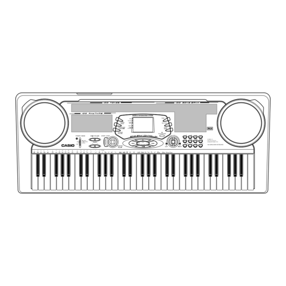
Casio CTK-541 Service Manual
Hide thumbs
Also See for CTK-541:
- User manual (42 pages) ,
- User manual (41 pages) ,
- User manual (36 pages)
Advertisement
Advertisement
Table of Contents

Related Manuals for Casio CTK-541


Summary of Contents for Casio CTK-541
- Page 1 CTK-541 JULY.1999 CTK-541 ELECTRONIC KEYBOARD INDEX...
-
Page 2: Table Of Contents
CONTENTS Specifications ........................... 1 Block Diagram ..........................3 Circuit Description ..........................4 Adjustment ............................8 Major Waveforms ........................... 10 Printed Circuit Boards ........................11 Schematic Diagrams ........................15 Exploded View ..........................19 Parts List ............................20... -
Page 3: Specifications
16 notes maximum (8 for certain tones) Auto accompaniment Rhythm patterns: Tempo: Variable (236 steps, = 20 to 255) Chords: 2 fingering methods (CASIO CHORD, FINGERED) Rhythm controller: START/STOP, SYNCHRO/FILL-IN Accomp volume: 0 to 9 (10 steps) Song bank Tunes:... - Page 4 ELECTRICAL Current drain with 9 V DC: Nominal Limit 330 mA ± 20% No sound output 330 mA 990 mA ± 20% Maximum volume 990 mA with 16 keys C1 to D3 pressed in Synth-Lead 1 Volume: Maximum, Touch response: ON(Velocity MAX) Phone output level (Vrms with 8 Ω...
-
Page 5: Block Diagram
BLOCK DIAGRAM COM1 ~ COM16 LCD Driver KS0066U-10B LSI3 Buttons Keyboard SEG1 ~ SEG40 KI0,KI1 FI0 ~ FI7 DB4 ~ DB7 FI8~FI10 Phone/Output MIDI IN MIDI OUT Filter (L) KC0 ~ KC7 Q206 Power Amp. TA8248K IC201 Filter (R) GT913F(T) MD0 ~ MD15 Q205 LSI1... -
Page 6: Circuit Description
Down Start/ Synchro/ Chord Accomp Stop Fill-In Book Volume Transpose/ Song KO10 Rhythm Tone Tune/MIDI Bank CASIO KO11 Fingered Normal Chord Play/ KO12 Right Stop Left Pause NOMENCLATURE OF KEYS F#3 G#3 A#3 C#4 D#4 F#4 G#4 A#4 C#5 D#5... - Page 7 CPU (LSI1: GT-913F) The 16-bit CPU contains a 1k-byte RAM, three 8-bit I/O ports, two timers, a key controller and serial interfaces. The CPU detects key velocity by counting the time between first-key input signal FI and second-key SI from the keyboard.
- Page 8 Pin No. Terminal In/Out Function +5 V source Ground (0 V) source MRDB Read enable signal output for the sound source ROM 83 ~ 98 MD0 ~ MD15 In/Out Data bus Reset signal output for the DSP In/Out Data bus for the LCD driver LCD DRIVER (LSI3: KS0066U-10B) The LCD driver can drive a dot matrix LCD having 40 segment and 16 common lines.
- Page 9 FILTER BLOCK Since the sound signals from the CPU is stepped waveforms, the filter block is added to smooth the waveforms. Amp. Filter TA8248K Block MSM6755B-17 POWER AMPLIFIER (IC201: TA8248K) The power amplifier is a two-channel amplifier with standby switch. The following table shows the pin function of IC201.
-
Page 10: Adjustment
ADJUSTMENT MAIN PCB 1) Items to be adjusted: Measuring Instrument Item Vop voltage setting Voltmeter 2) Adjustment and Test Point Locations Test point (TOP VIEW) (BOTTOM VIEW) — 8 —... - Page 11 3) Equipment connection/Procedure Vop voltage setting Voltmeter Output CP3-CP4 Input Input Input Output Output Adjust Adjust for Connection Point Signal Connection Point Voltmeter CP3-CP4 Adjust for 3.90 ~ 4.00V read- ing on voltmeter under the temparature 20 ~ 25 °C. Make fine adjustment accord- ing to the following instruc- tion.
-
Page 12: Major Waveforms
MAJOR WAVEFORMS 1 Clock pulse 2 Power source CVDD GT913F(T) pin 15 JD connector pin 13 3 APO signal JD connector pin 12 4 Sound waveform (R-ch) Tone: 6 JB connector pin 1 Whistle (59) 7 JB connector pin 2 JD connector pin 6 Key: 5 Sound waveform (L-ch) Volume: Max. -
Page 13: Printed Circuit Boards
PRINTED CIRCUIT BOARDS Main PCB JCM456-MA1M Top View Main PCB JCM456-MA1M Bottom View — 11 —... - Page 14 Sub PCB JCM453-MA2M Top View Sub PCB JCM453-MA2M Bottom View — 12 —...
- Page 15 Console PCB JCM453-CN1 Top View Console PCB JCM453-CN1 Bottom View — 13 —...
- Page 16 Keyboard PCB JCM618T-KY1M Top View Keyboard PCB JCM618T-KY1M Bottom View Keyboard PCB JCM618T-KY2M Top View Keyboard PCB JCM618T-KY2M Bottom View — 14 —...
-
Page 17: Schematic Diagrams
SCHEMATIC DIAGRAMS Main PCB JCM456-MA1M — 15 —... - Page 18 Sub PCB KDM453-MA2M — 16 —...
- Page 19 Console PCBs JCM453-CN1 — 17 —...
- Page 20 Keyboard PCBs JCM618T-KY1M / KY2M — 18 —...
-
Page 21: Exploded View
EXPLODED VIEW ´ ´ ´ ´... -
Page 22: Parts List
PARTS LIST CTK-541 Notes: This parts list does not include the cosmetic parts, which parts are marked with item No. "R-X" in the exploded view. Contact our spare parts department if you need these parts for refurbish. Prices and specifications are subject to change with- out prior notice. - Page 23 PARTS PRICE LIST CTK-541 Item Code No. Part Name Specification PRICE CODE Main PCB 6928 2120 PCB/ASSY (MA1M) M241173*1 D1-D4 2775 2079 DIODE/CHIP DA227TL LSI1 2012 5005 GT913F(T) LSI2 2012 6501 LSI/MC MSM538002E-S1GS-KDR1 LSI3 2012 5935 LSI/LCD DRIVER KS0066U-10B 2105 4746...
- Page 24 Item Code No. Part Name Specification PRICE CODE Panel unit 3831 1096 SPEAKER S12J89A 1908 6418 SCREW 3335 6804 LD-B10427E 6927 3890 RUBBER/INTERCONNECTOR M440759-1 6927 3920 REFLECTOR M240922-1 3122 3698 HMBV4BG2W106NLUAZG 6927 3420 HOLDER/CFL M440758-1 6927 3900 PACKING M440760-1 6921 5031 KNOB M311859A-1 6927 0510...
- Page 25 CASIO TECHNO CO.,LTD. Overseas Service Division Nishi-Shinjuku Kimuraya Bldg. 1F 5-25, Nishi-Shinjuku 7-Chome Shinjuku-ku, Tokyo 160-0023, Japan...