Table of Contents
Advertisement
Advertisement
Table of Contents

Related Manuals for Casio CTK-591


Summary of Contents for Casio CTK-591
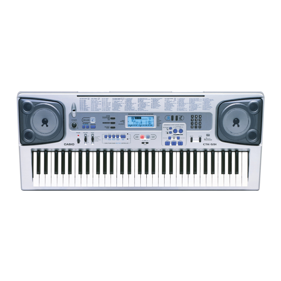
- Page 1 CTK-591 APR. 2003 CTK-591 ELECTRONIC KEYBOARD INDEX Ver.1 : Dec. 2003...
-
Page 2: Table Of Contents
24 notes maximum (12 for certain tones) Auto Accompaniment Rhythm Patterns: Tempo: Variable (216 steps, = 40 to 255) Chords: 3 fingering methods (CASIO CHORD, FINGERED, FULL RANGE CHORD) Rhythm Controller: START/STOP, INTRO, NORMAL/NORMAL FILL-IN, VARIATION/VARIA- TION FILL-IN, SYNCHRO/ENDING Accomp Volume: 0 to 127 (128 steps) - Page 3 Other Functions Transpose: 25 steps (–12 semitones to +12 semitones) 101 steps (A4 = approximatery 440Hz ±50Cents) Tuning: Terminals MIDI Terminals: IN, OUT Assignable Jack: Standard jack (sustain, sostenuto, soft, rhythm start/stop) Headphone/Output Terminal: Stereo standard jack Output Impedance: 100Ω Output Voltage: 4V (RMS) MAX Microphone In:...
-
Page 4: Block Diagram
BLOCK DIAGRAM — 3 —... -
Page 5: Circuit Description
STOP FILL-IN KEY CONTROL KEY CONTROL PRACTICE SING STEP 3 — /TRANSPOSE /TRANSPOSE PHRASE ALONG MODE MODE MODE MODE STEP 1 FULL RANGE CASIO FINGERED NORMAL CHORD CHORD METRO- NORMAL SCORING SPEAK INTRO START/STOP /FILL-IN /FILL-IN NOME RIGHT SONG OPEN TOUCH... -
Page 6: Adjustment
ADJUSTMENT DISPLAY PCB 1) Items to be adjusted: Item Measuring Instrument Vop voltage setting Voltmeter 2) Adjustment and Test Point Locations (TOP VIEW) 30 pin 33 pin VLCD 3) Equipment connection/Procedure Vop voltage setting Voltmeter Output VLCD Input Input Input Output Output Adjust... -
Page 7: Printed Circuit Boards
PRINTED CIRCUIT BOARDS Main PCB M704-MA1M Top View LCD PCB M704-LCD1M Top View — 6 —... - Page 8 Sub PCB JCM704-MA2M Top View — 7 —...
- Page 9 DISASSEMBLY 1. Remove the battery cover and then the battery. 2. Remove 29 screws and then the upper case. 3. Remove 5 screws, 4 speaker cords, 1 power cord, 2 battery cords, 3 connectors (JH, JM, JN) and then the PCB ASSY (MA2M).
- Page 10 4. Remove 4 screws, 6 connectors (JA, JB, JH, JJ, JK, JL) and then the PCB ASSY (MA1M). Screws Connectors Connectors Connectors 5. Remove 3 screws, 1 connector (JQ) and then the PCB ASSY (CN2M). Screws Connector 6. Remove 2 screws and then the PCB ASSY (CN3M). Screws —...
- Page 11 7. Remove 2 screws, the volume slider, and then the PCB ASSY (CN4M). Screws Volume slider 8. Remove 6 screws and then the LCD ASSY (LCD1M). Screws Note: Tighten the screws in the order from 1 to 6 when reassembling. —...
- Page 12 9. Remove 28 screws and then the PCB ASSY (CN1M). Note: Fix the LED (D4, D5, D50, D53, D54) to the PCB according to the height as shown in the figure below while paying attention to the polarity. Refer to the illustration on the PCB for the details of the polarity. Anode Cathode D50, D52, D53...
- Page 13 10.Remove 13 screws and then the lower case. Cushion Note: Tighten the screw with the arrow mark in the figure first when reassembling. 11.Remove 19 screws and then the PCB ASSY (KY1M, KY2M). 12.Remove the rubber keys. Projection Note: Pay attention to the positions of the rubber keys as one of them has a different length. Match the projections of the rubber keys with the holes of the lower case when reassembling.
- Page 14 13.Remove 21 screws and then the white keys. Note: Pay attention to the positions of the screw holes when reassembling. 14.Remove the black keys. — 13 —...
-
Page 15: Diagnostic Program
DIAGNOSTIC PROGRAM Initial Setup a. Connect an AC cord. b. Connect a Pedal cord. c. "MODE" switch: NORMAL d. "Main" volume: MAX e. Connect a MIDI cable (In-Out). Note: If there is no pedal or MIDI cable, pedal or MIDI check can be skipped. How to start diagnostic program a. - Page 16 Diagnostic program Message on LCD 1. Console check 1 Press "0" button to enter "Console check". DP3: 00 *Confirmation sound sounds. 2 Press buttons in the order from No.1 to No2C. DP3: BUTTON NO. NOTE: The button numbers are written in hexadecimal numerals. Press the "SPLIT"...
- Page 17 Message on LCD 5. Sound check 1 Press the "4" button to enter "Sound check". DP3: MIN * When standing in the center, the judge hears the minimum test sound in an equal volume from both right and left speakers. 2 Press the "5"...
-
Page 18: Schematic Diagrams
SCHEMATIC DIAGRAMS Main PCB M704-MA1M — 17 —... - Page 19 Sub PCB M704-MA2M — 18 —...
- Page 20 Console PCB M704-CN1M/CN4M/CN5M/CN6M/CN7M — 19 —...
- Page 21 Console PCB M704-CN2M/CN3M — 20 —...
- Page 22 Display PCB M704-LCD1M — 21 —...
- Page 23 Keyboard PCBs JCM618T-KY1M/KY2M — 22 —...
-
Page 24: Exploded View
EXPLODED VIEW — 23 —... -
Page 25: Parts List
PARTS LIST CTK-591 Notes: This parts list does not include the cosmetic parts, which parts are marked with item No. "R-X" in the exploded view. Contact our spare parts department if you need these parts for refurbish. Prices and specifications are subject to change with- out prior notice. -
Page 26: Specifications
Code No. Part Name Specification Price Code Remarks Item Main PCB 1011 7066 PCB ASSY/MA1M TK-RJM502710*001 2105 6350 IC XC62FP3302PR 6930 9981 IC TC74VHCT08AF (EL) 1012 1581 LSI MR27V3202FSKMAZ020 1008 9487 IC SN74LV20APWR 1011 6471 IC TC74VHC153FT(EL) 1011 6470 IC SN74LV174ANSR 1007 9244 LSI UPD915GF-3BA(T) - Page 27 Code No. Part Name Specification Price Code Remarks Item Keyboard PCBs 1005 3891 PCB ASSY/KY1M M140687*9 D501 - D564 2301 0101 DIODE 1S2473T-77-T 1005 3893 PCB ASSY/KY2M M140688*9 D565 - D622 2301 0101 DIODE 1S2473T-77-T Keyboard Unit 6922 2720 KEY SET/LT WHITE M312118*1 6922 2730 KEY SET/LT WHITE M312118*2...
- Page 28 Ver.1 : Dec. 2003 Replacement of the PARTS LIST (P25 ~ P26) CASIO TECHNO CO.,LTD. Overseas Service Division 6-2, Hon-machi 1-Chome Shibuya-ku, Tokyo 151-8543, Japan...